PAW SolexMini TW Installation and operation manual

PAW GmbH & Co. KG
Böcklerstr. 11, D-31789 Hameln, Germany
Phone: +49-5151-9856-0, Fax: +49-5151-9856-98
2016/05 996091425-mub-en –V04 1
Installation and Commissioning Instructions
Transfer station DN 15
SolexMini TW
[Hydraulics]

1 General information
2 996091425-mub-en –V04 2016/05
Contents
1General information .........................................................................................................3
1.1 About these instructions................................................................................................ 3
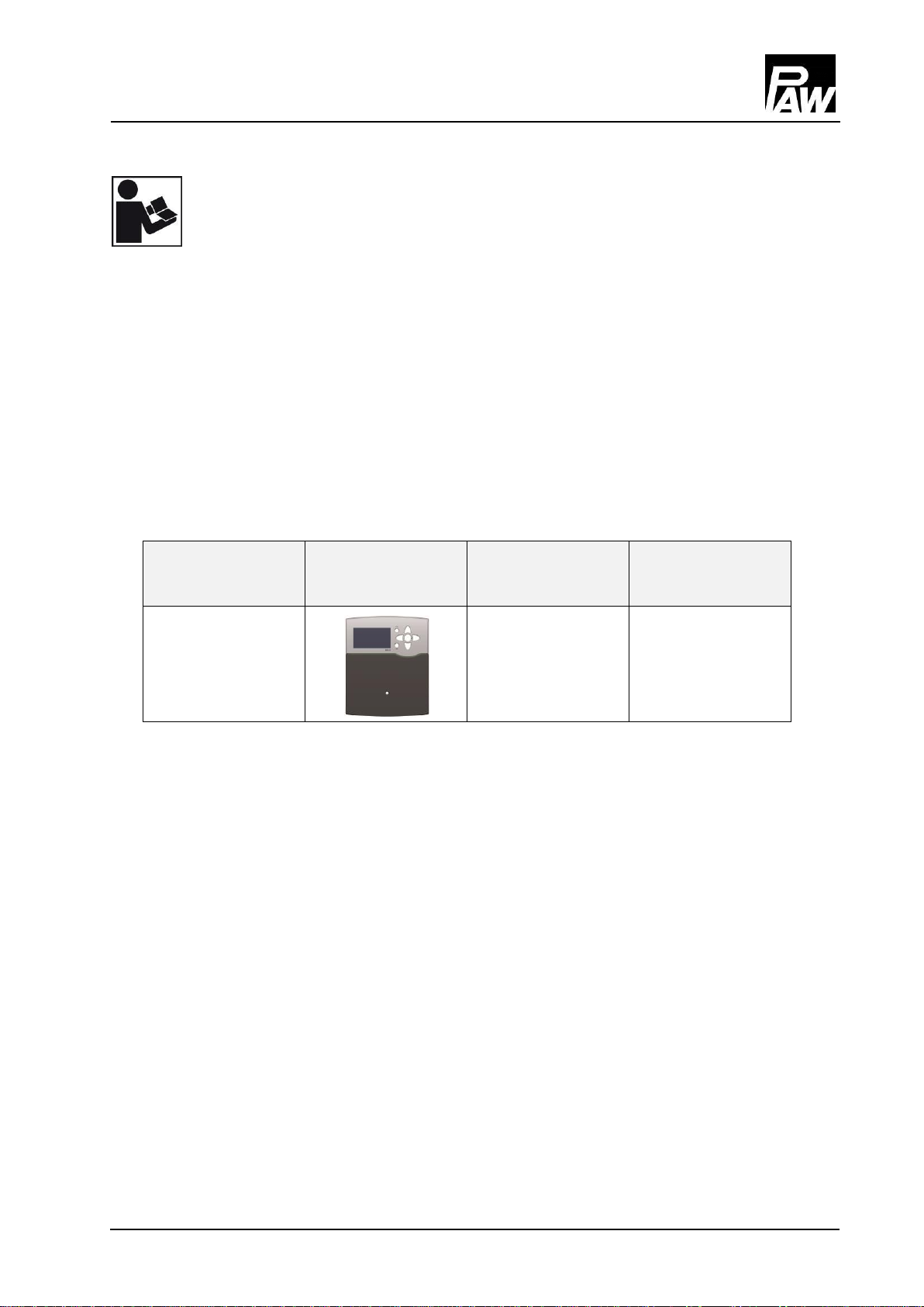
1.2 About this product......................................................................................................... 4
1.3 Designated use............................................................................................................. 5
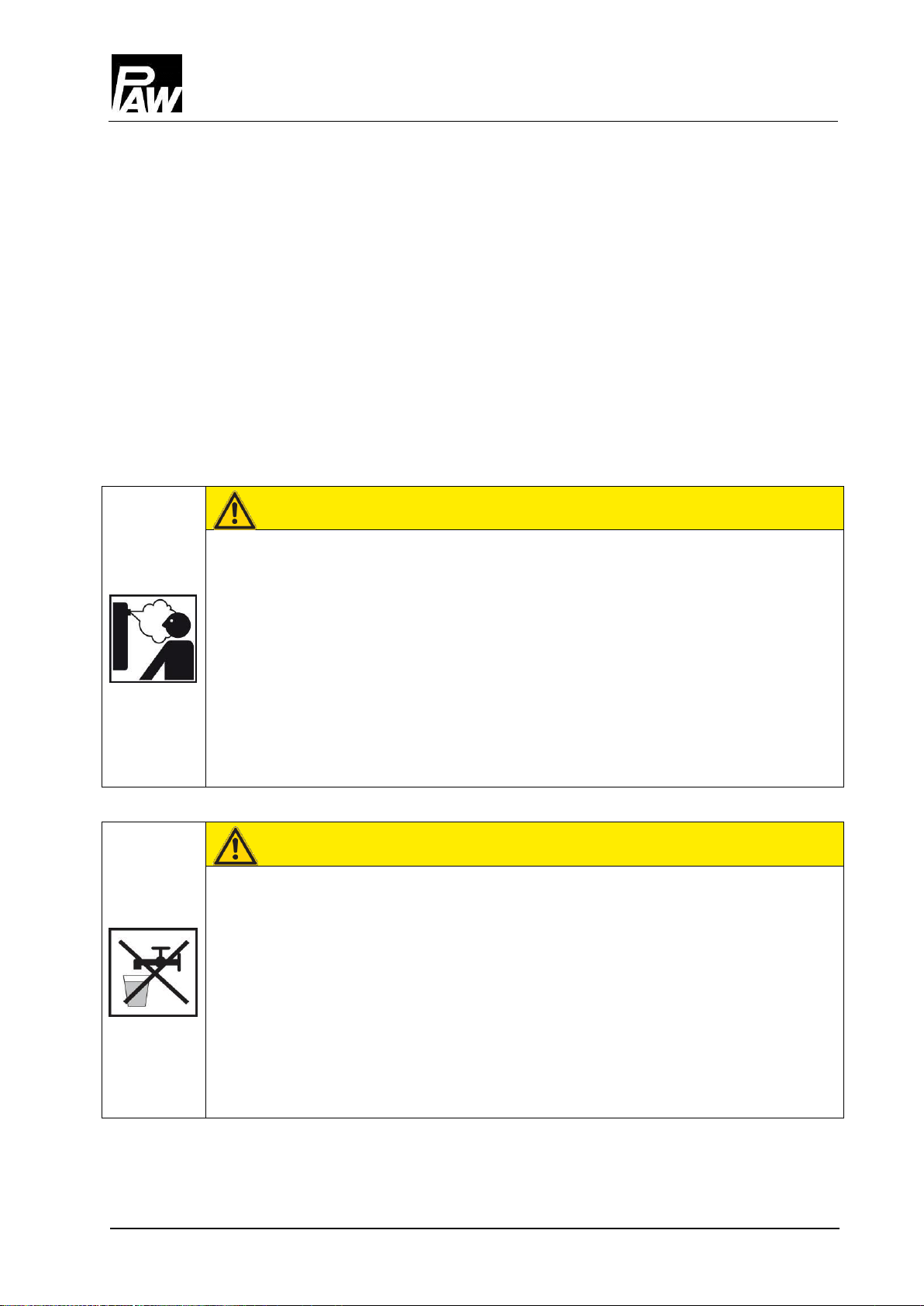
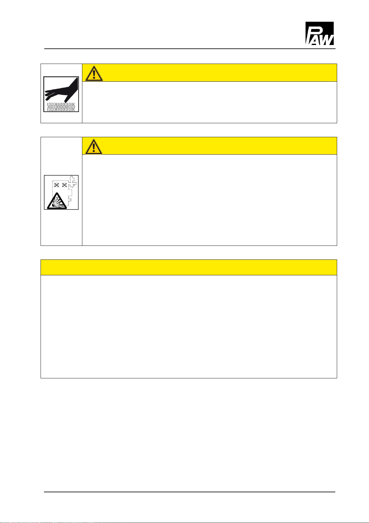
2Safety instructions ...........................................................................................................6
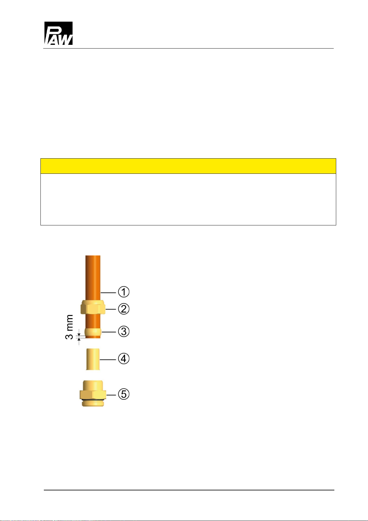
3Assembly and installation [specialist]................................................................................8
3.1 Controller connection.................................................................................................. 11
4Commissioning [specialist].............................................................................................12
4.1 Flushing and filling the secondary circuit..................................................................... 13
4.2 Flushing and filling the solar circuit ............................................................................. 14
4.3 Parameters: SolexMini TW with controller SC5.14...................................................... 19
5Maintenance [specialist].................................................................................................20
5.1 Draining the solar circuit ............................................................................................. 21
5.2 Deinstallation.............................................................................................................. 21
6Spare parts [specialist] ..................................................................................................22
6.1 Primary circuit SolexMini TW (6091425) ..................................................................... 22
6.2 Secondary circuit SolexMini TW (6091425) ................................................................ 23
7Technical data...............................................................................................................24
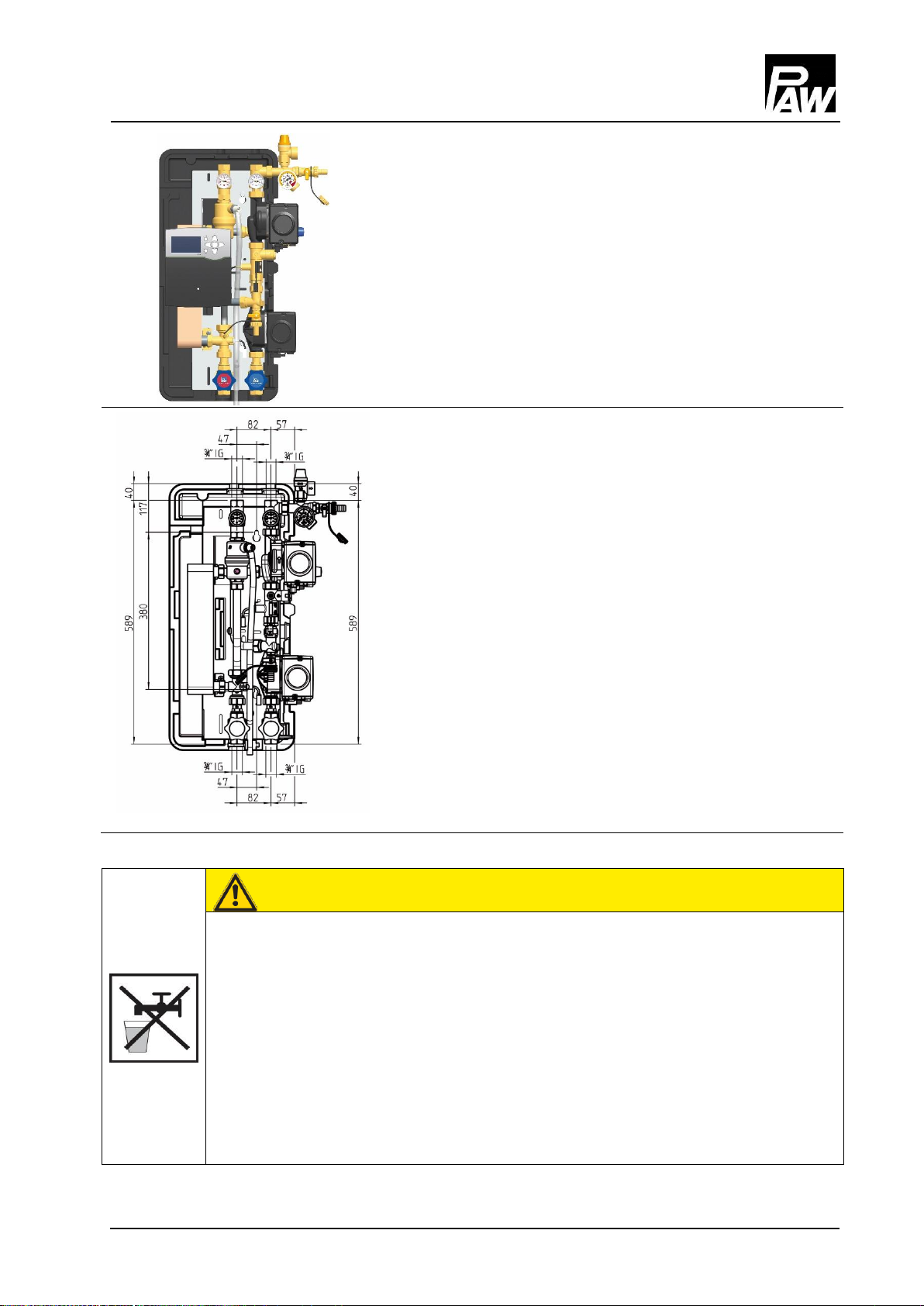
7.1 Dimensional drawing SolexMini TW............................................................................ 25
7.2 Pressure drop characteristic curve SolexMini TW....................................................... 25
8Function of the check valves [specialist] .........................................................................26
9Commissioning report....................................................................................................28
Item no. 996091425-mub-en - Version V04 –Issued 2016/05
Translation of the original instructions
We reserve the right to make technical changes without notice!
Printed in Germany –Copyright by PAW GmbH & Co. KG
PAW GmbH & Co. KG
Böcklerstraße 11
D-31789 Hameln, Germany

1 General information
2016/05 996091425-mub-en –V04 3
1General information
Carefully read these instructions before installation and commissioning.
Save these instructions in the vicinity of the installation for future reference.
1.1 About these instructions
These instructions describe the functions, installation, commissioning and operation of the
transfer station SolexMini TW.
The chapters called [specialist] are intended for specialists only. For other components of
the solar system, such as collectors, storage tanks, expansion tanks and controllers, please
observe the instructions of the corresponding manufacturer.
Item number
Controller SC5.14
Flow rate
(maximum)
Collector surface
(maximum)
6091425
750 l/h
30 m2

1 General information
4 996091425-mub-en –V04 2016/05
1.2 About this product
The SolexMini TW is a premounted group of valves and fittings, checked for tightness and used
to transfer the heat from the primary circuit (solar circuit) to the secondary circuit (domestic hot
water or storage tank circuit).
It contains a preset controller as well as important fittings for the operation of the system:
Ball valves with integrated thermometers in the solar circuit (flow and return)
Piston valves in the secondary circuit (flow and return)
Check valves to avoid undesirable gravity circulation in the flow and return
of the solar circuit
Pressure relief valves to prevent inadmissible overpressures in the station
Pressure gauge to display the system pressure in the solar circuit
Vent valves for an easy venting of the solar circuit
Fill and drain valves with caps to flush, fill and drain the solar circuit
Electronic flow rate sensors for heat quantity balancing and speed control
of the secondary pump depending on the performance (primary)
On the heating side, the installation must be equipped with a safety group that can be
ordered separately.
The expansion tank required for operation must be adapted to the size and the requirements
of the installation and must be ordered separately.
The cap valve (item no. 5302) or the tank connection coupling (item no. 5310), also
separately available, allow an easy installation and separation of the expansion tank
from the solar installation.
The wrapping materials are made of recyclable materials and can be disposed of
with recyclable materials.

1 General information
2016/05 996091425-mub-en –V04 5
1.3 Designated use
The SolexMini may only be used as a transfer station between the solar and the domestic
hot water circuit or between the solar and the storage tank circuit, taking into consideration
the technical limit values indicated in these instructions.
Due to its design, the station must only be mounted and operated as described in
these instructions!
Only use PAW accessories with the transfer station.
Improper usage excludes any liability claims.
Under the influence of solar radiation, the collectors can get very hot.
The solar fluid in the solar circuit can heat up to more than 100 °C.
Flush and fill the solar circuit only if the collector temperatures are
below 70 °C.
Scope of delivery
Schematic structure
SolexMini TW

2 Safety instructions
6 996091425-mub-en –V04 2016/05
2Safety instructions
The installation and commissioning as well as the connection of electrical components require
technical knowledge commensurate with a recognised vocational qualification as a fitter for
plumbing, heating and air conditioning technology, or a profession requiring a comparable
level of knowledge [specialist].
The following must be observed during installation and commissioning:
relevant local and national regulations
accident prevention regulations of the professional association
instructions and safety instructions of this manual
WARNING
Danger of scalding due to vapour escape!
With pressure relief valves, there is a risk of scalding due to vapour escape.
During installation, check if the local conditions require the connection of a
discharge line to the safety group.
For this purpose, please observe the instructions regarding the pressure
relief valve.
The pressures calculated by the installation planner for the expansion
tank and the operating pressure of the installation must be set.
WARNING
Personal injury due to polluted potable water!
Heating water contains harmful substances that must not be washed into the
domestic hot water circuit.
If the station has been used to charge a buffer tank, there is still heating water
in the valves and fittings and in the pump of the secondary circuit, even after
draining. The heating water can not be completely removed.
The station must not be connected to a domestic hot water circuit
any more.

2 Safety instructions
2016/05 996091425-mub-en –V04 7
CAUTION
Risk of burns!
The valves, fittings and pumps may heat up to more than 100 °C during operation.
The insulating shell must remain closed during operation.
CAUTION
Personal injury and damage to property due to overpressure!
By closing the two ball valves in the primary circuit, the safety group is separated
from the heat exchanger. A rise in temperature in the storage tank causes high
pressures which can result in personal injury or damage to property!
Only close the ball valves for service and maintenance.
If you close the ball valves in case of servicing, do also put the pumps
out of operation and close the ball valves in the secondary circuit.
NOTICE
Material damage due to mineral oils!
Mineral oil products cause lasting damage to seals made of EPDM, whereby the sealant
properties get lost. We do not assume liability nor provide warranty for damage to property
resulting from sealants damaged in this way.
It is imperative to avoid that EPDM gets in contact with substances containing
mineral oils.
Use a lubricant based on silicone or polyalkylene and free of mineral oils, such as
Unisilikon L250L and Syntheso Glep 1 of the Klüber company or a silicone spray.

3 Assembly and installation [specialist]
8 996091425-mub-en –V04 2016/05
3Assembly and installation [specialist]
The location of installation must be dry, load-carrying, frost-proof and protected against
ultraviolet radiation. Furthermore, the access to the control and safety equipment must
be guaranteed at all time during operation!
The discharge lines of the pressure relief valves must be conducted into heat-resistant
collecting containers of corresponding size. Thus, an uncontrolled discharging into the
environment is avoided and the refilling of the circuits is facilitated!
NOTICE
Material damage due to high temperatures!
As the solar fluid can be very hot near the collector, the fitting assembly must be installed at a
sufficient distance from the collector field. It may be necessary to install an intermediate tank
in order to protect the expansion tank.
Not included in
the scope of delivery!
Accessories: cutting-ring compression fitting
1. Push the union nut ② and the cutting ring ③ onto the
copper pipe ①. The pipe must protrude at least 3 mm
from the cutting ring in order to ensure the force
transmission and the sealing.
2. Insert the support sleeve ④ into the copper pipe.
3. Insert the copper pipe with the plugged-on individual
parts (②, ③ and ④) all the way into the housing of
the compression fitting ⑤.
4. First, screw the union nut ② manually.
5. Tighten the union nut ② by rotating one full turn.
Secure the housing of the compression fitting ⑤
against distort, in order to avoid damaging the
sealing ring.

3 Assembly and installation [specialist]
2016/05 996091425-mub-en –V04 9
1. Remove the station from the packaging.
2. Copy the mounting holes to the mounting surface.
You can find a corresponding drilling template on
the paper board under the station.
3. Drill the holes and insert appropriate wall plugs into
the holes.
4. Screw in the screws and let them stick about 3 cm
out of the wall.
5. Remove the insulating front shell. Hang the module
onto the screws and tighten the screws.
WARNING
Personal injury due to polluted potable water!
Heating water contains harmful substances that must not be washed into the
domestic hot water circuit.
If the station has been used to charge a buffer tank, there is still heating water
in the valves and fittings and in the pump of the secondary circuit, even after
draining. The heating water can not be completely removed.
The station must not be connected to a domestic hot water circuit
any more.

3 Assembly and installation [specialist]
10 996091425-mub-en –V04 2016/05
6. Connect the transfer station to the installation
by using the piping:
① Solar flow from the collector
② Solar return to the collector
③ Flow to the storage tank
④ Return from the storage tank
All thread connections have ¾" internal threads.
7. Mount the safety group, consisting of the pressure
relief valve [c], the fill valve [d] and the pressure gauge
[e] to the connection of the return ball valve [b].
8. Connect the pipe for the expansion tank below the
pressure gauge [e] and fix the bracket for the
expansion tank.
For service work on the expansion tank, we
recommend the installation of a cap valve
(item no. 5302) or a tank connection coupling
(item no. 5310) on the expansion tank.
NOTICE
Note regarding the expansion tank
While flushing and filling the station, the expansion tank must not be connected in order
to avoid that dirt particles are washed in.
9. Adapt the initial pressure of the expansion tank
to the installation and connect the expansion tank.
Please observe the separate instructions regarding
the expansion tank!
10. Check all thread connections and tighten them
if necessary.

3 Assembly and installation [specialist]
2016/05 996091425-mub-en –V04 11
3.1 Controller connection
WARNING
Risk to life and limb due to electric shock!
Prior to commencing electrical work on the controller, pull the mains plug!
Only after completing all installation work as well as the flushing and filling,
the mains plug of the controller can be plugged into a socket.
Thus, an unintentional start of the motors is avoided.
Connection scheme SC5.14
Connection scheme (881)
for DHW systems and heating systems
Connection scheme (882)
for heating systems
Please observe the separate instructions regarding the controller SC5.14!
1. Connect the temperature sensors to the controller:
Collector sensor S1
Storage tank bottom: S2
Integrated: S3, S9, (FlowRotor)
Collector sensor S1
Storage tank 1 bottom: S2
Storage tank 2 bottom: S4
(required on site, item no. E13180)
Integrated: S3, S9, (FlowRotor)
2. Tighten all union nuts and thread connections.
The installation of the transfer station is now completed and the station can be put
into operation.
dV
dV

4 Commissioning [specialist]
12 996091425-mub-en –V04 2016/05
4Commissioning [specialist]
Please observe the following safety instructions regarding the commissioning of the station:
WARNING
Risk of burns and scalding!
The fittings can heat up to more than 100 °C. Therefore, it is not allowed to flush
or fill the system if the collectors are hot (intense solar radiation). Please note that
hot solar fluid can leak from the pressure relief valves in case of too high system
pressure!
During venting, solar fluid may escape as vapour and cause scalding!
Flush and fill the system only if the collector temperatures are
below 70 °C.
NOTICE
Risk of frost!
It is often not possible to completely drain solar installations after flushing. Thus, there is a risk
of frost damage when flushing with water. Therefore, flush and fill the solar installation only with
the solar fluid used later.
Use a water and propylene glycol mixture with maximum 50% of propylene glycol
as solar fluid.
NOTICE
Note regarding the sequence of commissioning
Flush and fill the installation in the following order:
1. Fill the secondary circuit.
2. Vent the heat exchanger by means of the safety valve.
3. Flush and fill the solar circuit of the heat exchanger.
4. Flush and fill the collector field.
5. Flush and fill the (entire) solar circuit.
This avoids that dirt particles are flushed into the heat exchanger and guarantees
that possibly absorbed heat can be dissipated.

4 Commissioning [specialist]
2016/05 996091425-mub-en –V04 13
4.1 Flushing and filling the secondary circuit
NOTICE
Note regarding the expansion tank
To prevent that dirt particles of the solar system are washed into the expansion tank, some
manufacturers recommend to disconnect the expansion tank from the solar circuit during
flushing and filling. Please observe the instructions of the manufacturer on this topic.
Depending on the application, the secondary circuit is filled (charging of a domestic hot water
tank) via the valves at the tank or (charging of a buffer tank) via the valves of the heating
system. Make sure that only potable water must be used in the first case mentioned. In the
second case mentioned, only heating water treated according to VDI 2035 / Ö-Norm H5195-1
must be used.
To avoid that dirt particles are washed into the heat exchanger, shut the ball valves of the
module and wash out the present dirt particles/scale residues before the initial commissioning
of the tank.
1. Open the piston valves [C|D].
2. Vent the secondary circuit by operating the
pressure relief valve [A] on the secondary side.
Make sure that the electrical components do
not get wet.
3. Fill the secondary circuit by means of the
valves at the domestic hot water tank or
at the heating system.
4. During operation, vent the station at the
pressure relief valve [A] to eliminate the
air still present in the heat exchanger.
Domestic hot water circuit

4 Commissioning [specialist]
14 996091425-mub-en –V04 2016/05
4.2 Flushing and filling the solar circuit
The valves and fittings required to flush and fill the station are integrated in the transfer station.
Make sure not to wash dirt particles into the heat exchanger and the expansion tank. Therefore,
only use flush and fill stations with fine filters. The solar circuit is flushed against the flow
direction. Therefore, make sure that the pump of the solar circuit can not be switched on.
Ball valve with integrated check valve
(Normal flow direction in the figure: downwards)
0°
45°
90°
Check valve is operating,
flow only in flow direction.
Check valve is not operating,
flow in both directions.
Ball valve closed,
no flow.

4 Commissioning [specialist]
2016/05 996091425-mub-en –V04 15
Airstop
The Airstop with manual vent valve is used to vent the solar
installation. To ensure a perfect venting of the solar circuit,
the flow velocity in the flow line must be at least 0.3 m/s.
Pipe diameter [mm]
Flow rate at 0.3 m/s
∅ outside
∅ inside
l/h
l/min
15
13
~ 143
~ 2.4
18
16
~ 217
~ 3.6
22
20
~ 339
~ 5.7
The air separated from the solar fluid is collected in the upper part of the Airstop
and can be released at the vent plug [j].
WARNING
Danger of scalding due to vapour escape!
The escaping fluid can heat up to more than 100 °C and cause scalding.
Carefully open the vent plug and close it again as soon as medium
escapes.
Venting the solar system after commissioning
At the beginning, vent the solar installation daily and then weekly or monthly,
depending on the quantity of vented air. Thus, an optimum operation of the solar
installation is ensured. Check the system pressure after venting and increase it to
the specified operating pressure if necessary.
j

4 Commissioning [specialist]
16 996091425-mub-en –V04 2016/05
1. Disconnect the expansion tank from the solar
installation. This avoids that dirt particles still
present in the pipes are washed into the
expansion tank.
2. Put the check valve out of operation by
turning the ball valve [a] into position 45°
(see page 14).
3. The return ball valve [b] must be closed.
4. Connect the flush and fill station:
- pressure hose to the fill valve [h]
- flush hose to the drain valve [d].
5. Open the fill and drain valves [h|d] and put
the flush and fill station into operation.
6. Slowly open and close the return ball valve [b]
during flushing, in order to vent the pump
section.
7. Flush the solar circuit until the solar fluid
exits without bubbles.
8. Close the drain valve [d] while the filling pump
is running and increase the system pressure
to about 5 bars.
The system pressure is displayed on
the pressure gauge [e].
9. Close the fill valve [h] and switch off
the pump of the flush and fill station.
10. Check the pressure gauge to see if the
system pressure decreases and eliminate
leaks where necessary.
Observe the pressure
(max. 6 bars)!

4 Commissioning [specialist]
2016/05 996091425-mub-en –V04 17
WARNING
Risk to life and limb due to electric shock!
Check if the sensors and the pumps are properly connected
to the controller and if the controller housing is closed.
Only then, the mains plug of the controller can be plugged into a socket.
11. Reduce the pressure on the drain valve [d] to the
operating pressure.
12. Connect the expansion tank to the solar circuit and
set the operating pressure of the solar system by
means of the flush and fill station (see instructions
regarding the expansion tank).
13. Close the fill and drain valves [h|d].
14. Put the check valves into operating position
by turning the ball valves [a|b] into position 0°
(see page 14).
15. Connect the controller to the mains. Set the pump
of the solar circuit in the manual mode to ON
according to the controller instructions.
16. Let the pump of the solar circuit run at maximum
rotation speed for at least 15 minutes. Vent the
solar installation in the meantime several times at
the vent plug [j] of the Airstop, until the solar fluid
exits without bubbles (see page 15).
17. If necessary, increase the system pressure to the
operating pressure.
SC5.14

4 Commissioning [specialist]
18 996091425-mub-en –V04 2016/05
18. Remove the hoses of the flush and fill station
and screw the sealing caps onto the fill and drain
valves.
The sealing caps only serve to protect the valves
against dirt. They are not designed to take up high
system pressures. The ball valves must be closed
to guarantee tightness.
19. Mount the insulating front shell.
20. Set the controller to automatic mode
(see controller instructions).
21. Mount the insulating front shell of the transfer
station.
The commissioning of the solar installation is
now completed.
Please fill in completely the commissioning report
on page 28.

4 Commissioning [specialist]
2016/05 996091425-mub-en –V04 19
4.3 Parameters: SolexMini TW with controller SC5.14
The parameters for the sensors and pumps are preset in the controller. If you select and save
another system, the parameters are reset to the factory settings. In this case, the parameters
in the menu must be modified. Thus, a proper functioning of the installation is ensured. You will
find a detailed description of the operation of the controller in the separate controller manual.
Preset system SolexMini TW (1 collector; 1 storage tank)

5 Maintenance [specialist]
20 996091425-mub-en –V04 2016/05
5Maintenance [specialist]
Depressurise the installation for service and maintenance work on the SolexMini.
WARNING
Risk of burns and scalding!
The valves, fittings and the solar fluid can heat up to more than 100 °C.
The solar fluid can escape as vapour and cause scalding.
Only carry out maintenance work if the collector temperatures
are below 50 °C.
Wait until the solar fluid has cooled down to maximum 50 °C.
1. Close the ball valves [a|b] and release the solar fluid
at the fill and drain valve [h].
Make sure that the solar fluid is collected in
a heat-resistant container.
2. Change the faulty part against the new part.
3. Fill the solar circuit as described in 4.2 Flushing and
filling the solar circuit (see page 14).
Table of contents
Other PAW Water Heater Accessories manuals