9Bu er tank with coil
UKVS 20-300/1000
4. CONNECTION AND START-UP
4.1 Connec on
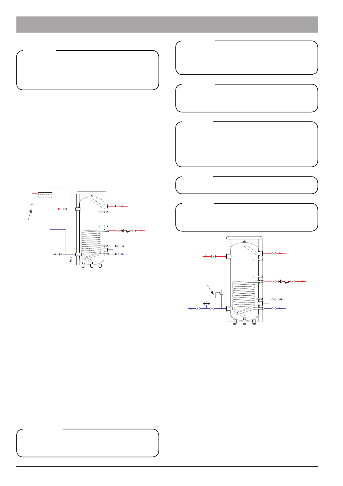
1. Connect the supply line from the heat source (4)
2. Connect the return line to the heat source (10 in UKVS
20-300/500, or 11 in UKVS 20-750/1000)
3. Connect the hea ng system supply line (3)
4. Connect the return line from the hea ng system (9 in
UKVS 20-300/500, or 12 in UKVS 20-750/1000)
5. Connect the coil supply line, (7) in UKVS 20-300/500, or
(8) in UKVS 20-750/1000, and the return line from the
coil to the connector pipe (11) in UKVS 20-300/500, or
(10) in UKVS 20-750/1000.
6. Install the required temperature sensors (5)
7. If necessary, connect the electric hea ng unit to the con-
nector pipe (15) in UKVS 20-300/500, or (16) in UKVS 20-
750/1000.
4.2 Start-Up
A er connec ng all components of the C/H system, do
the following:
1. Fill up the C/H system with the hea ng medium
2. Check ghtness of all connec ons
3. A er checking for ghtness, insulate the pipelines to-
gether with the tank ngs thoroughly
4. Fill up the C/H system with the hea ng medium and vent
the system
A er the installa on and levelling the tank, follow the proce-
dure below (for the connector pipe numbers, refer to Fig. 3,
4, 5 and 6):
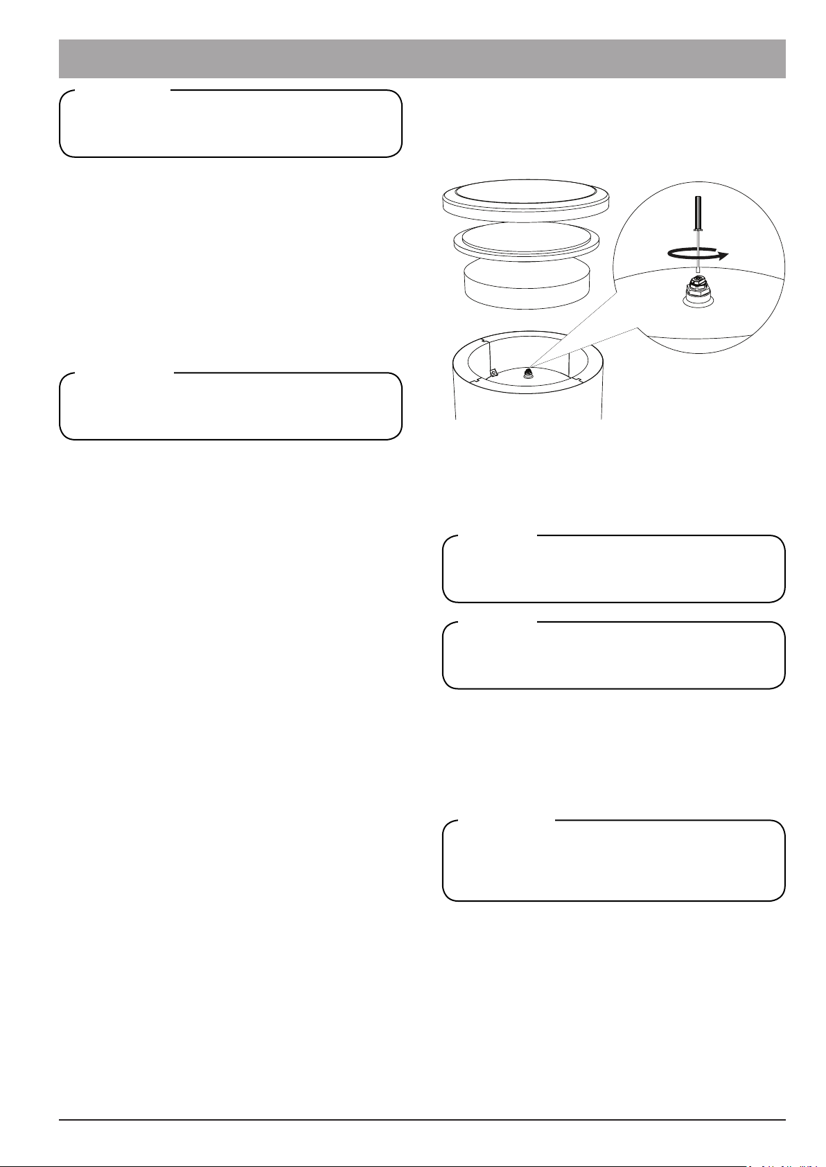
Filling and ven ng the bu er tank:
You can ll the bu er tank directly from the C/H system or
through the tank drain valve. Vent the tank and the C/H sys-
tem a er lling them. Vent the unit through the vent installed
in the top head of the tank (see Fig. 11.)
Fig. 11Ven ng the bu er tank
The coil can operate with almost any central hea ng system
or other heat source such as solar panels, heat pumps, etc.
However, when installing the coil, a en on should be paid to
the fact that the max pressure in the supply system may not
exceed the max opera ng pressure of the coil and that the
temperature of the hea ng medium in the system may not
exceed the allowable coil opera ng temperature. For the allo-
wable coil opera ng temperatures, see Table 1 Technical data.
Connec ng the Coil
The lower return connec ons to the hea ng source and
from the hea ng system can be connected in opposite
confi gura on.
Informa on
We recommend connec ng the tank connector pipes
with the system lines by means of unions to allow discon-
nec on of the tank, if required.
Informa on
Ensure that the en re C/H system is lled with the he-
a ng medium before hea ng the system up for the rst
me or a er a longer break in its opera on.
CAUTION
4.3 Thermal Insula on of the System
In order to minimize thermal energy losses, insulate all con-
nector pipes, pipelines and temperature sensor covers tho-
roughly a er the installa on of the unit and performance of
the leak proof test. For this purpose, use thermal insula on
of correctly selected thickness and thermal insula on para-
meters.
Lack of thermal insula on, its incorrect thickness or in-
sula on made of inadequate materials will cause decre-
ase of thermal insula on proper es of the unit and the
system.
Informa on
A er comple on of the above steps, the system is ready for
opera on. You can use the facility hea ng system a er star-
ng up the heat source and reaching the required temperatu-
re of the hea ng medium.
Switch OFF the hea ng units and wait un l the he-
a ng medium cools down completely in the C/H system
before ven ng the buff er tank.
CAUTION
4.4 Frost Protec on
If you plan to interrupt opera on of the unit and there is a risk
of freezing the hea ng medium in the tank, drain the tank and
the en re hea ng system associated with it completely.
INSTALLATION AND OPERATING MANUAL


 null")
 null")


 Operation and maintenance instructions")