Nic MA-3000 User manual

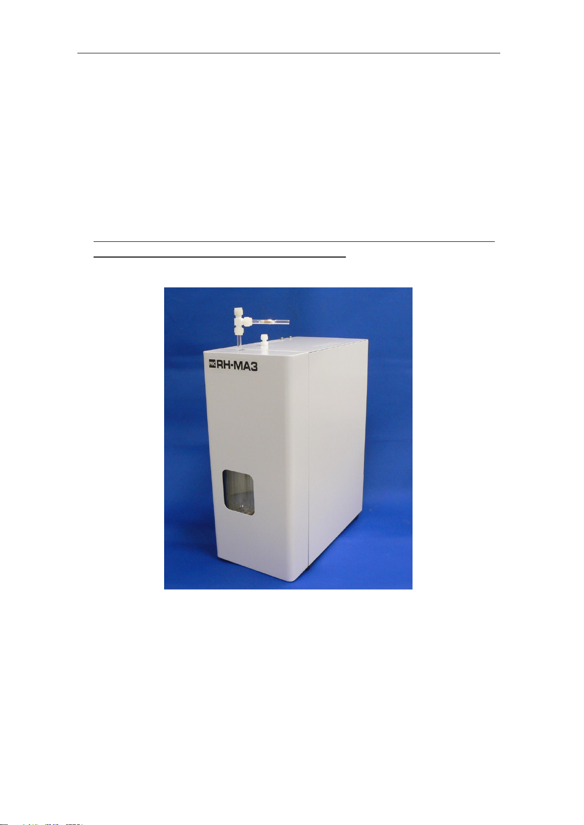
Mercury Collection Tube Heating Furnace Unit
for MA-3000
RH-MA3
Instruction Manual
NIC-600-2208-04
Nippon Instruments Corporation

Instruction Manual MA-3000+RH-MA3 NIC-600-2208-04
Instruction Manual
Mercury Collection Tube Heating Furnace Unit
RH-MA3
Contents
1. INTRODUCTION............................................................................................................. 1
1.1. Safety precautions................................................................................................... 1
1.1.1. Meaning of safety alert symbols....................................................................... 1
1.1.2. Installation precautions..................................................................................... 1
1.1.3. Precautions with maintenance ......................................................................... 1
2. SYSTEM OUTLINE......................................................................................................... 2
2.1. Operation ................................................................................................................. 3
2.2. Part names and functions........................................................................................ 4
3. SPECIFICATIONS .......................................................................................................... 7
3.1. Equipment specifications......................................................................................... 7
3.2. Installation Environment........................................................................................... 7
4. EQUIPMENT INSTALLATION........................................................................................ 8
4.1. Equipment installation and connection.................................................................... 8
5. MEASUREMENT............................................................................................................ 9
5.1. Measurement Operation Flowchart......................................................................... 9
5.2. Equipment needed to make measurements.......................................................... 10
5.3. Preparing to make measurements......................................................................... 10
5.4. Measurement..........................................................................................................11
5.4.1. Setting the measuring conditions....................................................................11
5.4.2. Setting the table conditions ............................................................................ 12
5.4.3. Creating a calibration curve............................................................................ 13
5.4.4. Measuring an unknown sample (collection tube)........................................... 16
5.4.5. Interrupting the measurement........................................................................ 19
5.4.6. Terminating the measurement........................................................................ 19
6. MAINTENANCE............................................................................................................ 20
6.1. Inspection items..................................................................................................... 20

Instruction Manual MA-3000+RH-MA3 NIC-600-2208-04
6.1.1. Daily inspections............................................................................................. 20
6.1.2. Annual inspections ......................................................................................... 21
6.2. Failures during measurement................................................................................ 22
6.2.1. Reduced peak sensitivity................................................................................ 22
6.2.2. No standard gas repeatability......................................................................... 23
6.2.3. Incorrect blank values..................................................................................... 24
6.3. Parts replacement.................................................................................................. 25
6.3.1. Washing the coupling, joint, and gas scrubbing bottle................................... 25
6.3.2. Replacing the RH2 heater mercury collection tube........................................ 26
6.3.3. Regenerating collection tube 65L................................................................... 26
6.3.4. Fuse replacement........................................................................................... 27
6.3.5. Replacing the air pump (P2) tube................................................................... 28
7. CONTACT..................................................................................................................... 30

Instruction Manual MA-3000+RH-MA3 NIC-600-2208-04
1
1. Introduction
1.1. Safety precautions
1.1.1. Meaning of safety alert symbols
Warning
Indicates that incorrect handling could result in death or severe injury to
the operator.
Caution
Indicates that incorrect handling could pose a specific potential hazard
resulting in injury to the operator or damage to property.
1.1.2. Installation precautions
Warning
•Ensure to connect the earth wire in preventing electric shocks.
1.1.3. Precautions with maintenance
Warning
•Ensure to turn OFF the power supply before doing any maintenance or it could
result in an electric shock.
Caution
•Before doing maintenance work on the heater section ensure to turn off the
power switch and wait until the heater cools down to room temperature. Failure to
observe this could result in the operator suffering a burn.
•Exercise caution when handling any of the glass parts. Failure to observe this
could result in them being damaged.
•Do not turn on or off the power of the MA-3000 main unit while any buffer solution
is present. Failure to observe this could result in a backflow of the buffer solution,
thus disabling use of the collection tube.
Instruction Manual MA-3000+RH-MA3 NIC-600-2208-04
2
2. System Outline
The RH-MA3 is the collection tube heating furnace for use with the MA-3000, and an
optional unit for use in measuring any mercury collected by the MA-3000 in a 160L mercury
collection tube in LPG, natural gas or atmospheric air.
It is strongly recommended that this manual be carefully read before using the system in
thereby maximizing its potential performance.
This Instruction Manual covers the operation and maintenance of the RH-MA3.
Please read the MA-3000 Instruction Manual as well.

Instruction Manual MA-3000+RH-MA3 NIC-600-2208-04
3
2.1. Operation
The machine is fully controllable from the MA-3000. It introduces carrier gas into the
detection section via an optional pump located at the rear of the RH-MA3.
The machine heats the mercury collection tube with heater RH1 (H6) in thus liberating the
gas collected by the collector, and then removes any acidic gases via the gas scrubbing
bottle.Any excess moisture in the dehumidifying bottle is then removed, and any mercury
selectively re-collected and condensed in RH2 (H7). After collecting the mercury the
machine heats RH2 in thus liberating any mercury gas and introduces it into the detection
section before measuring its absorbance.
Cooling fan
Electronic cooler
T-joint with septum with collection tube 65L
Mercury collection tube
Carrier gas
Cooling fan
Heater
(RH2)
To MA-3000
Heater
(RH1)

Instruction Manual MA-3000+RH-MA3 NIC-600-2208-04
4
2.2. Part names and functions
Inside the RH-MA3 cover
No.
Name
Function
Remarks
1
T-joint
(with septum)
(Used to charge standard gas)
S1031-6103-11
2
Mercury collection
tube 160L
Tube used to collect mercury as the
measurement target
160 mm long
3
Heater (RH1)
Heater used to heat the mercury
collection tube (H6)
4
Union
FLW-30-6U-S
5
Gas scrubbing
bottle
Removal of acidic gases etc.
N-1062-0801-401
6
Roller clamp
IUC-56-655-02
7
Dehumidification
bottle
Water removal
N-1062-0801-401
8
Electronic cooler
Cools the gas scrubbing bottle and
dehumidifying bottle
9
Reducing elbow
FLW-30-6UE4-C
10
Collection tube 65L
Removes any mercury in the carrier
gas
S1016-3401-00
Instruction Manual MA-3000+RH-MA3 NIC-600-2208-04
5
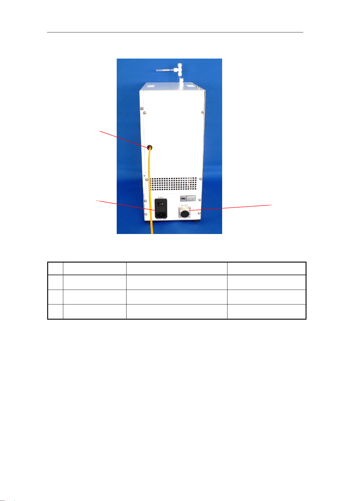
Rear of RH-MA3
No.
Name
Function
Remarks
11
Teflon pipe
(Φ4×Φ2)
Connects to the optional MA3
unit.
70 cm (standard)
12
AC INLET
Power supply port with power
switch
Includes built-in 4Afuse
13
MA-3000
connection terminal
Terminal for connection to
MA-3000
⑬
⑪
⑫

Instruction Manual MA-3000+RH-MA3 NIC-600-2208-04
6
Right side face of RH-MA3
No.
Name
Function
Remarks
14
Heater (RH2)
Heater used to heat the mercury
collection tube (H7)
15
Mercury collection
tube PE1
Recollects and condenses any mercury
L100mm
S1085-0820-00
16
Reducing union
Connection between collection tube and
Teflon tube
FLW-30-6RU4-S
⑭
⑮
⑯

Instruction Manual MA-3000+RH-MA3 NIC-600-2208-04
7
3. Specifications
3.1. Equipment specifications
Carrier gas:............................Indoor purified air
Sample:.................................160L mercury collection tube
Measurement range:.............0.01~1000ng
Dimensions and Weight:.......150W×280D×420mmH, 7kg
Source voltage:.....................Single-phase AC, 100 to 260V, 50/60Hz (3-pin socket)
Voltage source capacity:.......0.5kVA
Quality of power supply:........Should be free of any surges, harmonics, noise, etc.
3.2. Installation Environment
Room temperature:...............15 to 35°C
Vibration:...............................No vibrations strong enough to be felt by the human
body.
Dust and Fumes:...................Clean atmospheric environment free of fumes, dust, and
anything else that could affect the measurement. (No
smoking)
Installation space:..................1000W x 800D (mm) or larger with a rigid foundation and
capable of supporting a weight of about 60kg.
Other:.....................................Ensure to install the unit in a place out of direct sunlight
and not exposed to any air from air conditioners or
blowers.
Special notes:........................Ensure to not install the system in any place where
volatile halide reagents such as organic chlorine
solvents are handled. In addition, avoid installing it
anywhere those gases could be present.
Instruction Manual MA-3000+RH-MA3 NIC-600-2208-04
8
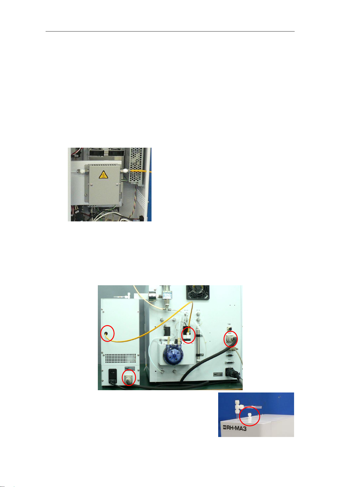
4. Equipment installation
4.1. Equipment installation and connection
(1) Remove the right side plate by loosening the 2 screws at the rear.
(2) Draw the yellow tube through the hole into the back panel before connecting it
to the collection tube of the recollection furnace using the reducing Teflon joint
FLW-30-6RU4-S.
*Lightly tighten it by hand before retightening 1/6
turn with a spanner.
(3) Connect a Teflon tube between the gas scrubbing bottle and the collection tube.
(4) Connect the MA-3000 and the RH-MA3 with the attached interlock cable.
(5) Connect the power cord to the RH-MA3 before plugging it into a wall outlet.
(6) Connect the yellow Teflon tube of the RH-MA3 to the IN port of valve V4 of the
optional unit at the rear of the MA-3000.
* The joint at top of RH-MA3 is used only when the
optional reducing vaporization unit RD-5+SC-5 of
MA-3000 is connected at the same time.
Instruction Manual MA-3000+RH-MA3 NIC-600-2208-04
9
5. Measurement
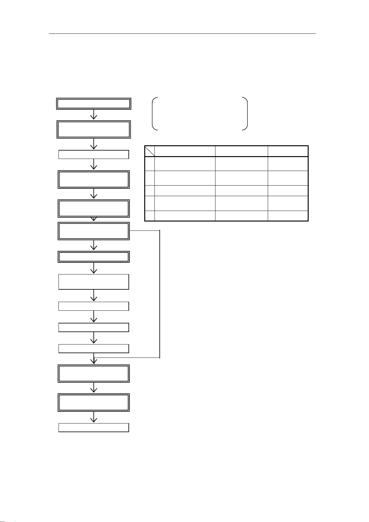
5.1. Measurement Operation Flowchart
Start the equipment
Stabilize the optical unit
Input the measurement
conditions
Start measurement
Heat the mercury collection
tube
Measurement
Cooling
Repeat
Purge the carrier gas
Replace mercury collecting
tube
Set the measurement
method to "heating furnace"
Drain the gas scrubbing
solution
Charge the gas scrubbing
solution
Measuring section MA-3000
Personal computer
Collection tube heating furnace
RH-MA3
Operation
Status name
Time
1
Collection tube heating
RH1 ATOMIZE
240 seconds
(Default value)
2
Sample gas
replacement
PURGE1
30 seconds
3
Measurement
MEASURE
60 seconds
4
Equipment purging after
measurement
MEASURE PURGE
30 seconds
5
Cooling
COOL
30 seconds
Set the measurement
method to "HEATING"
End

Instruction Manual MA-3000+RH-MA3 NIC-600-2208-04
10
5.2. Equipment needed to make measurements
(1) pH = 6.86 standard buffer solution
(2) Mercury standard gas box (MB-1)
(3) Gas tight syringe
5.3. Preparing to make measurements
(1) Verify the gas scrubbing bottle of the RH-MA3 contains no solution.
Note) Do not turn on or off the power of the MA-3000 main unit while any gas
scrubbing solution is present.
Failure to observe this could result in a backflow of the gas scrubbing
solution, thus disabling use of the collection tube.
(2) Start the MA3win control software.
(3) Turn on both the power switches of the MA-3000 and the RH-MA3.
(4) Set the optional unit setting of MA-3Win to "RH".
Select "System" - "Setup" from
the menu bar to open the
window.
(5) Charge the gas scrubbing solution.
①Open the roller clamps of both the gas scrubbing bottle and
the dehumidifying bottle, and fill the gas scrubbing bottle
with pH=6.86 standard buffer solution and distilled water at
a ratio of 1:1.
②Ensure the amount of the gas scrubbing solution is at a level
of about 20 mm higher than the end of the air outlet.
③Close the roller clamps of both the gas scrubbing bottle and
the dehumidifying bottle.
20mm
Instruction Manual MA-3000+RH-MA3 NIC-600-2208-04
11
5.4. Measurement
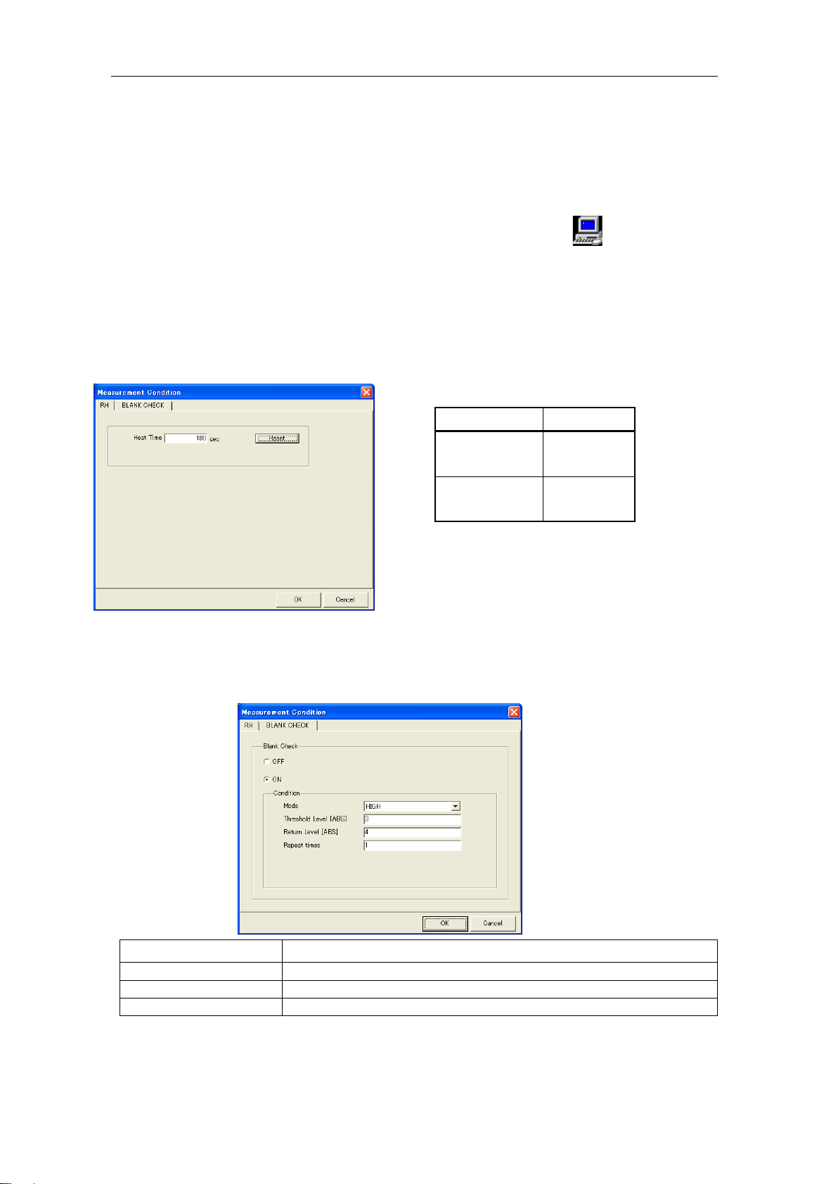
5.4.1. Setting the measuring conditions
Select “Run” - “Measurement Condition”from the menu or click the icon, and then
set the measuring conditions.
RH Heat Time
The time during which the heater (RH1) of the mercury collecting section will be
heated can be set. (Default value: 240 seconds)
If you measure the high concentration Hg, 240 seconds of RH Heat Time may not be
enough. Please extend the Heat Time.
BLANK CHECK
If an ABS higher than the setting is detected with the measurement of an unknown
sample, the measurement sequence is automatically executed again to reduce the
system blank.
Mode
Select whichABS: LOW or HIGH is used in the determination.
Threshold Value [ABS]
Executed if the measured value reaches a higher value.
Return Value [ABS]
Ends if the measured value reaches a lower value.
Repeat times
Max. 10
* Not executed when measuring standard samples.
Hg
Heat Time
~10ng
(LOW range)
240 sec
~1000ng
(HIGH range)
420 sec
Indication of Heat time
*If you measure the ambient air, 180
seconds of Heat Time is enough.
Instruction Manual MA-3000+RH-MA3 NIC-600-2208-04
12
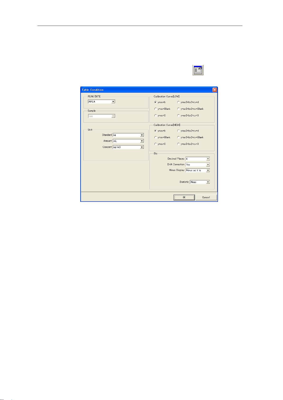
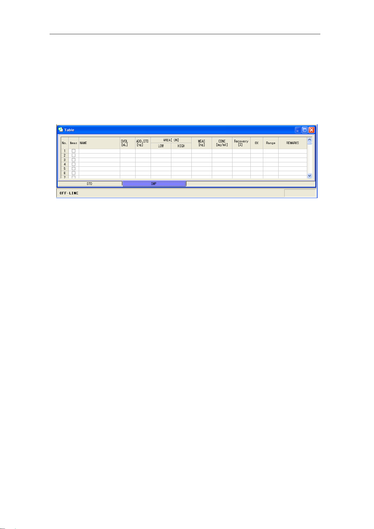
5.4.2. Setting the table conditions
Select “Run” - “Measurement Condition”from the menu or click the icon, and then
set the table conditions.
*Select the Calibration Curve according to the official method and the curve passing
through the blank (+Blank) with measurements of trace quantities of mercury close
to the blank value enable the best measurement results.
Instruction Manual MA-3000+RH-MA3 NIC-600-2208-04
13
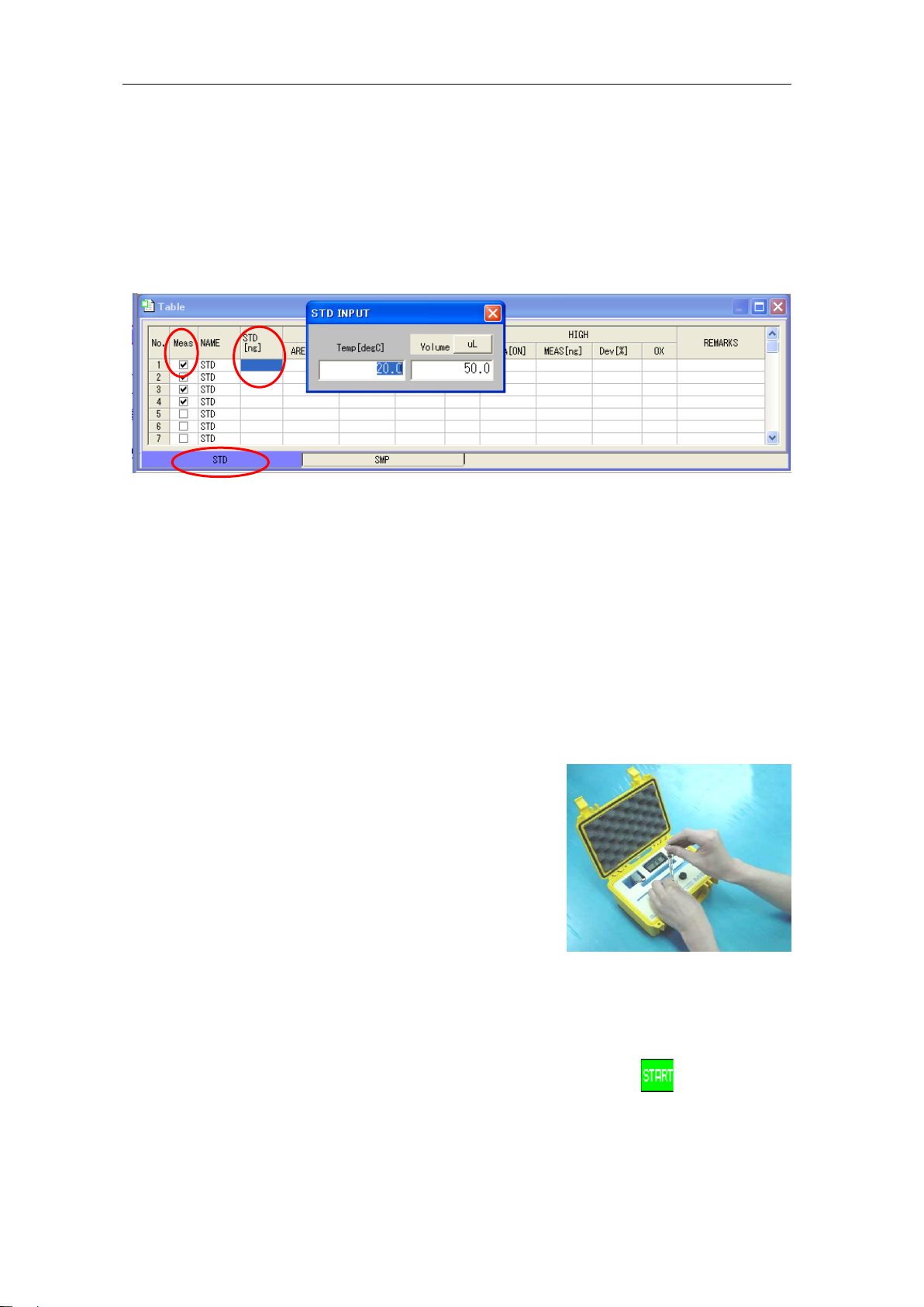
5.4.3. Creating a calibration curve
(1) Set the standard sample on the “Table” screen. Click the “STD” tag.
(2) Check the "Meas" field.
(3) Input a standard value.
Click the "STD" field to open the "STD INPUT" window. Input the thermometer
reading and volume of the sample of the standard gas box. The amount of mercury
will then be calculated automatically and input.
(The unit can be changed between "mL" and "uL" by clicking "uL" at the right of the
“Volume”field.)
* The initial blank measurements will result in high values. Make measurements
repeatedly before adopting a value after theABS has stabilized.
(4) Sample the gas from the standard gas box using a syringe. When sampling ensure
to move the piston up and down 2 or 3 times to ensure a good fit before collecting
the required amount of the sample.
* The temperature in the gas box not having stabilized will negatively affect the
reproducibility. Do not place the gas box anywhere exposed to airflow from an air
conditioner or other fans.
(5) Select “Run”- “Measurement start” from the menu or click the
icon to start the
measurement.
The measurement can also be started by pressing the F5 key on the keyboard.
(2)
(1)
(3)

Instruction Manual MA-3000+RH-MA3 NIC-600-2208-04
14
(6) Inject the sampled gas through the septum in one stroke.
* Injecting the gas before the start of
measurement will result in an incorrect
measurement.
(7) At the end of measurement the following message will display.
(8) After the measurement the calibration curve will be automatically updated.
The "OX" field can be used to select whether to adopt the calibration curve or not.
* In some cases the characters in the calibration curve
graph can turn red and "WARNING" display, as shown
in the left figure.
In this case the calibration curve will have fallen outside
the specified value range. Verify that there was no error
in the input of the amount of mercury or with the
equipment.
* The specified value can be changed from "Setup" -
"Calibration set".
(9) When measuring without interruption return to (2). Repeat the procedure the
required number of times.
Instruction Manual MA-3000+RH-MA3 NIC-600-2208-04
15
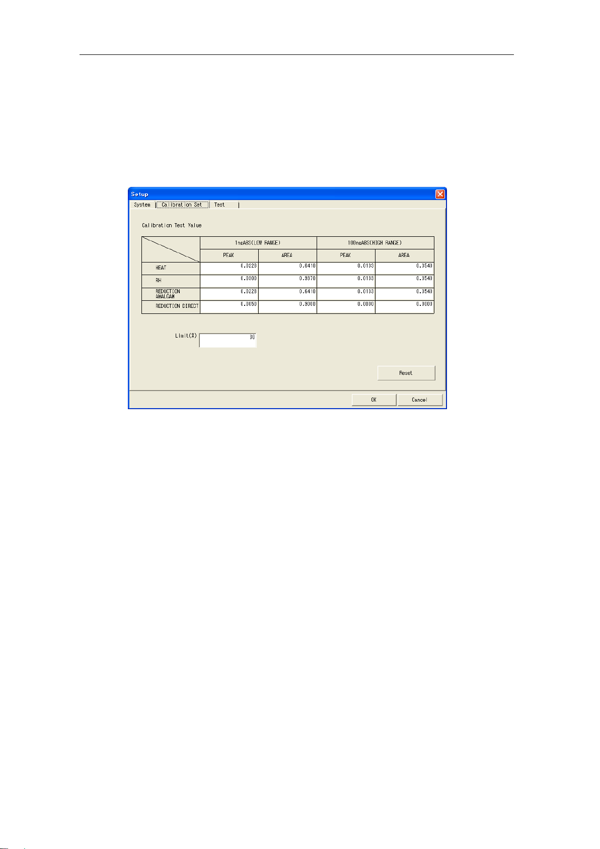
Setting the calibration curve
Set the accept/reject criteria for the calibration curve.
Calculate an ABS of 1ng or 100ng backward from the created calibration curve and
determine whether to accept or reject the calibration curve on the basis of the
deviation from the setting value.
ABS of Calibration Test Value
Reference values for PEAK and AREA for each measuring method and the medium
value of 1ng for a LOW range and 100ng for a HIGH range are installed.
Limit of Deviation between Values (%)
If the deviation between the value from the backward calculation and the setting value
falls out of this range, the arithmetic expression of the calibration curve will turn red
and a warning will be displayed.
Instruction Manual MA-3000+RH-MA3 NIC-600-2208-04
16
5.4.4. Measuring an unknown sample (collection tube)
(1) Change “Table” to “SMP”. Click the “SMP” tag.
(2) Check in the "Meas" field.
(3) Input the sample name in the "Name" field. Or select "Travel Blank" or "Operation
Blank".
Travel Blank : Used when a collection tube handled in the same manner as
sample collection tubes but not used for sampling is measured
and the measured value is then assumed as the correction
value.
Operation Blank : Used when a collection tube in the same washing lot as the
collection tube used for the sample measurement is measured
and the measured value is then assumed as the correction
value.
(4) Input the sample amount.
(5) Remove the collection tube.
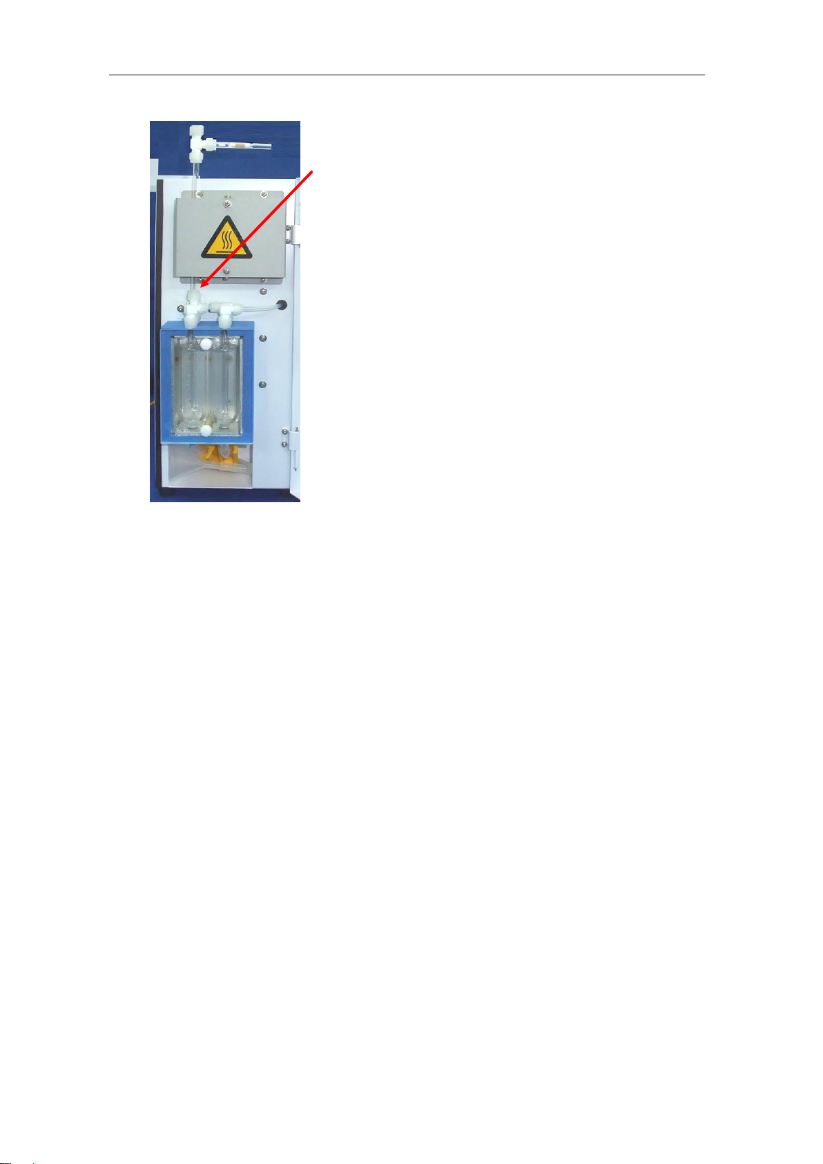
Instruction Manual MA-3000+RH-MA3 NIC-600-2208-04
17
Open the front panel of the RH-MA3, loosen the joint
fixing the collection tube in place under the collection
tube heating furnace (RH1), and then pull out.
Other manuals for MA-3000
2
This manual suits for next models
1
Table of contents
Other Nic Laboratory Equipment manuals


