5
RECOMMENDATIONS
Installation guide FFB brake motors
5286 en - 2017.09 / c
en
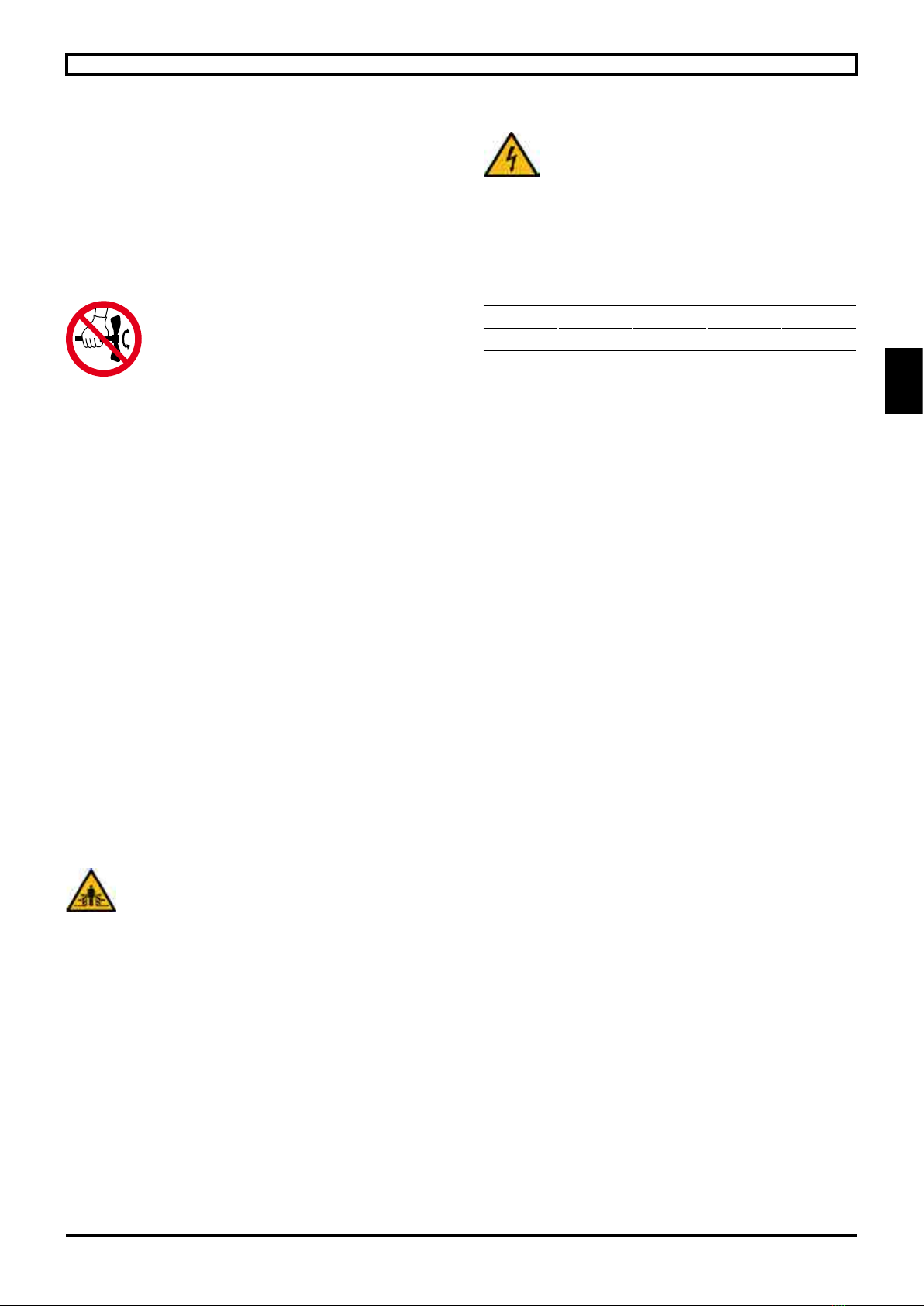
Do not knock the motor (terminal box, cover), the shaft or
the coupling during mounting, do not crush the seal, do not
project beyond the shoulder of the shaft.
Ensure correct brake motor cooling, the air intakes and outlets
must be kept clear.
Check that the loads applied to the motor shaft (especially
the belt tension) are compatible with the values stated in our
technical catalogues.
2.2.1 - Brake with options
It is prohibited to drive the extension in
manual rotation and the fan with the
parking brake applied, or the brake
released under load.
- Auto-return hand brake release (DLRA)
For brakes tted with a lever, push it towards the back of the
brake motor.
Whenever the brake has been released, make sure that
it is engaged once any maintenance operations have been
completed.
See dismantling/reassembly procedure in ref.5287 FFB
maintenance.
- (Manual) brake release lock off system (DLM)
For brakes tted with a DLM, proceed in the same way as the
DLRA to release the brake and then turn (clockwise) the DLM
handle in line with the DLRA to lock the brake in the released
position. When the brake is next powered up, it is engaged
automatically and the brake is operational again.
See dismantling/reassembly procedure in ref.5287 FFB
maintenance.
- Remote (electrical) brake release lock off (DMD)
For brakes tted with a DMD, supply the brake coil with
power separately from the motor. Once the brake is released,
supply the electromagnet on the lock control board with
power. Once the locking contactor is engaged, switch off the
brake coil power supply and then that of the control board.
The brake is held in the released position. When the brake is
next powered up, it is engaged automatically and the brake is
operational again.
Whenever the brake has been released, make
sure that it is engaged.
- Release indicator (open/close)
For brakes tted with a release indicator, while the brake is
supplied with power the armature actuates a microswitch
(discrete) xed on the backplate indicating brake release.
When the power is switched off, the microswitch changes
state in order to conrm that the brake is engaged.
- Wear indicator
For brakes tted with a wear indicator, while the brake is
supplied with power the armature actuates a microswitch
(discrete) xed on the yoke. If the brake lining is worn
(+ 0.6 mm) the microswitch is actuated and informs the user
of the need to adjust the air gap or change the brake lining if it
is less than the required minimum (See the “Adjusting the air
gap” procedure in ref.5287 FFB maintenance).
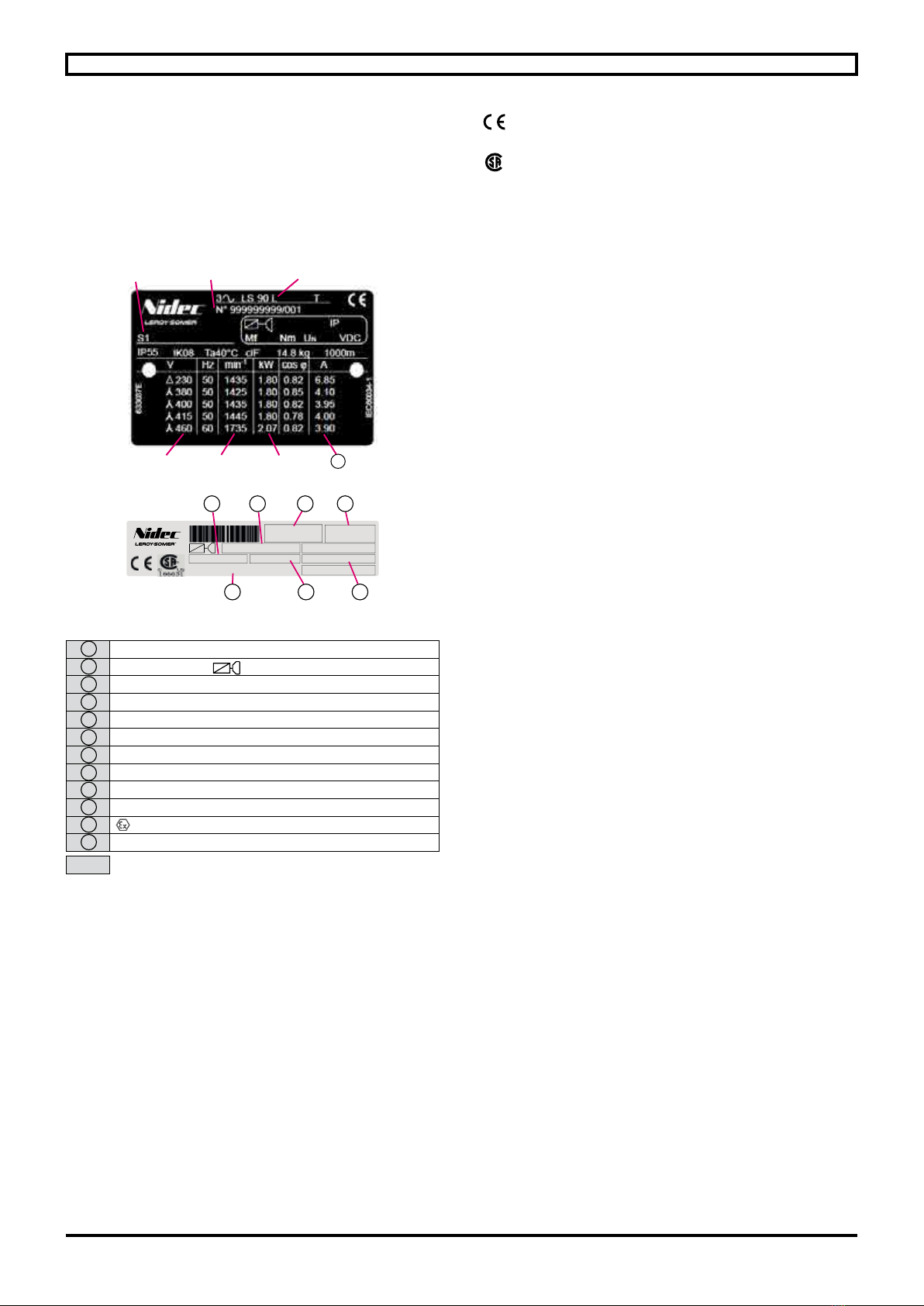
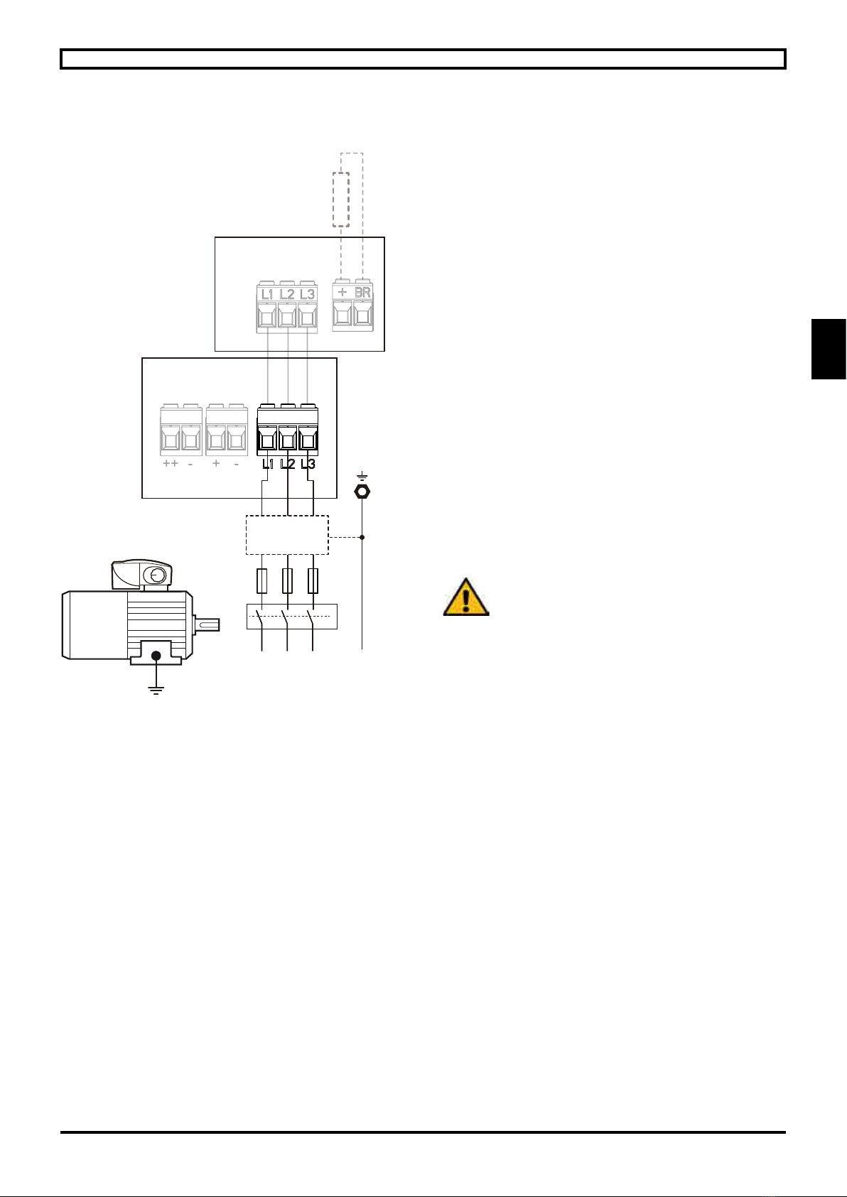
2.3 - Electrical connection
The cables should be connected with the power
off by qualied personnel, in accordance with
good practice, in compliance with the safety
conditions. Choose the protection system and
cables according to the information on the
nameplate (the voltage drop during the starting
phase must be less than 3%).
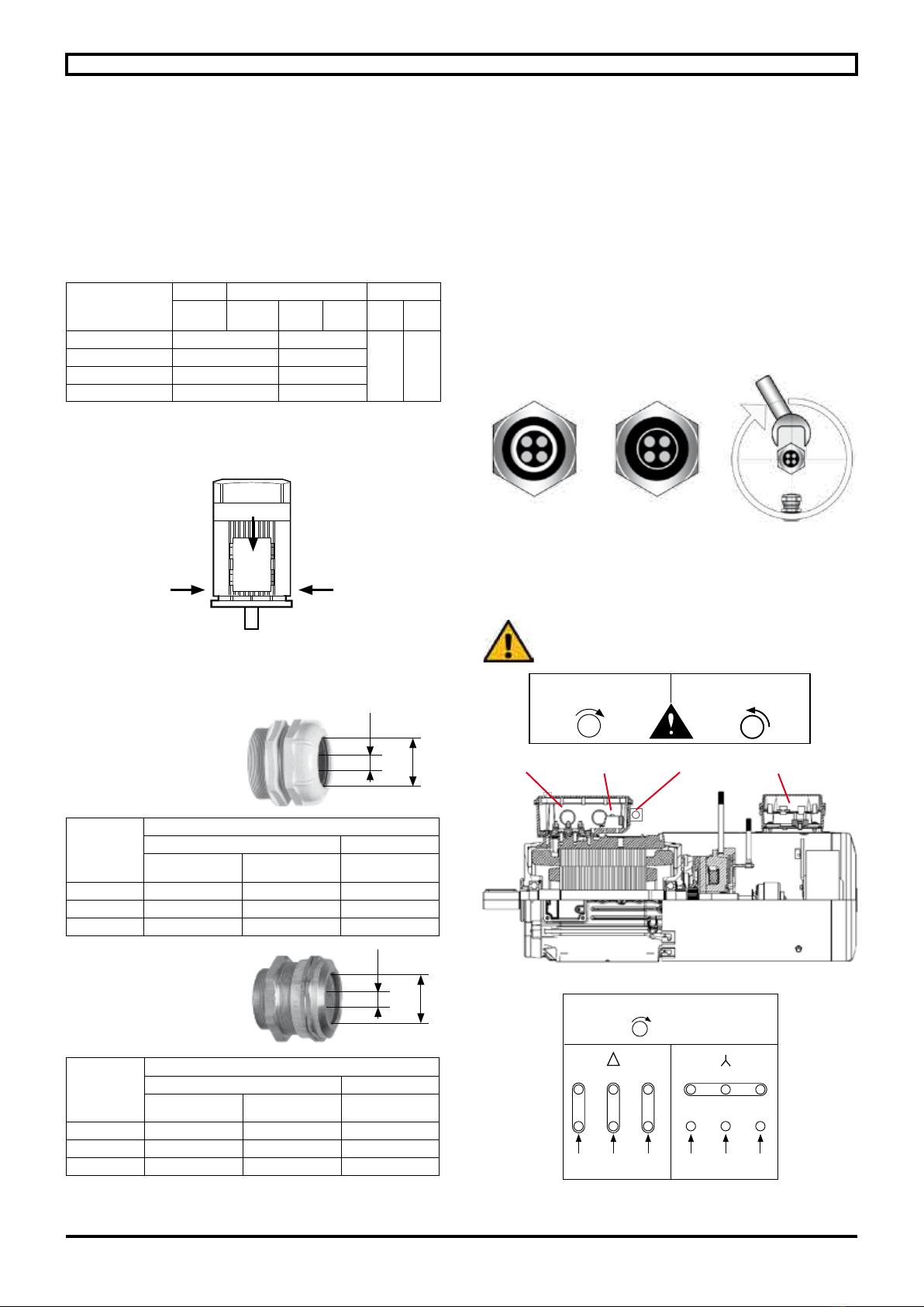
Tighten the terminal lock nuts, connectors and power supply
cables to the torque stated below (N.m):
M4 M5 M6 M8
Steel 1 2.5 4 10
If using cables without connectors, attach calipers.
- Do not place washers or lock nuts between the motor
connections and the connections on the power supply cable.
Connect the thermal protection devices and accessories
(section 3.5).
Ensure that the cable gland is watertight (the cable gland
must always correspond to the diameter of the cable used).
Incorporate a bend where the cable enters the terminal box
to prevent water entering via the cable gland.
Check the motor direction of rotation (section 3.1).
The internal terminal box connections must never be put
under any stress due to the cables connected by the user.
Earthing
It is mandatory to earth the brake motor (in the terminal
box and on the brake), and earthing must be performed in
accordance with current regulations (protection of workers).
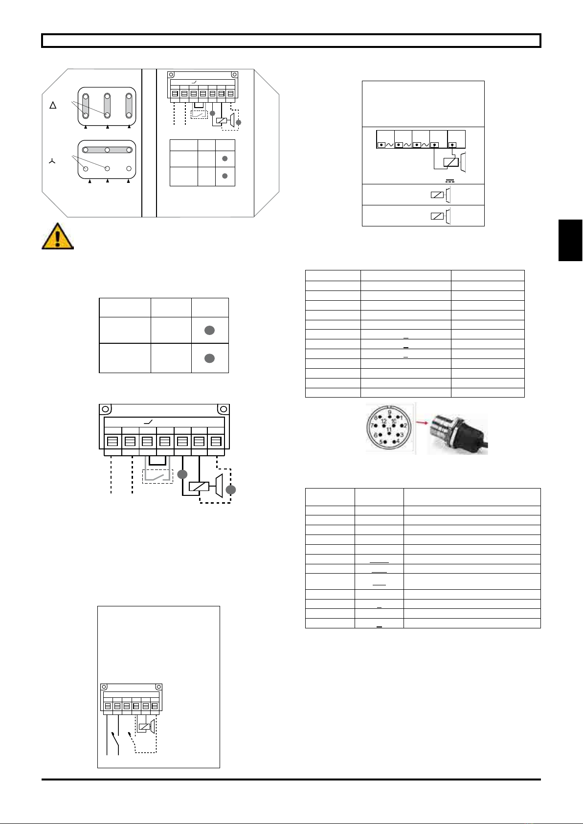
Power supply (see wiring diagrams under the terminal box
cover, section 3).
Brake motors with a built-in power supply are connected like
standard motors. They are tted with a DC coil (180 VDC).
The brake is supplied directly from the motor stator
(230/380/400/415/460/480 V) via a brake power supply unit,
rectier mounted in the terminal box.
For motors with different voltages, starting at reduced
voltage or operating at variable voltage or frequency, a
separate brake power supply must be provided. (The same
applies to a 20 VDC coil).
To reduce the brake application response time (mandatory
in Hoisting applications), it is necessary to switch off the
brake DC power supply at the same time as that of the
motor, usually via an auxiliary contact on the motor starting
contactor.