Nidec LEROY-SOMER LSPX Series Operating manual

Reference: 5725 en - 2020.02 / c
(F)LSPX ZONE 21 - Ex tb
(F)LSES ZONE 22 - Ex tc
Commissioning and
maintenance guide
Induction motors
three phase for
dusty EXplosive
ATmospheres

2
Maintenance and service guide - LSPX-FLSPX ZONE 21 - Ex tb – LSES-FLSES ZONE 22 - Ex tc
5725 en - 2020.02 / c
GENERAL WARNING
These symbols appear in this document whenever it is important to take special precautions during installation, operation,
maintenance or servicing of the motors.
It is essential that electric motors are installed by experienced, qualied and authorized personnel.
In accordance with the main requirements of EC Directives, the safety of people, animals and property should be ensured when tting
the motors into machines.
Particular attention should be given to equipotential ground or earthing connections.
The noise levels of the machines, measured under standard conditions, complies with the requirements of the standard and does
not exceed the maximum value of 85 dB(A) pressure at 1 metre.
The following precautions must be taken before working on any stationary device:
• AC voltage disconnected and no residual voltage present
• Careful examination of the causes of the stoppage (jammed transmission - loss of phase
- cut-out due to thermal protection - lack of lubrication, etc.)
Electric motors are industrial products. They must therefore be installed by qualied, experienced and
authorized personnel. The safety of people, animals and property must be ensured when tting the motors into machines
(please refer to current standards).
Personnel likely to intervene on electrical installations and equipment in explosion risk areas shall be trained and authorized
specically for this type of equipment.
Indeed, knowledge is required about the risks specic to electricity, but also those due to chemical properties and physical
characteristics of the products used in the installation (gas, vapours, dusts), as well as the environment in which the equipment
operates. These elements condition the risks of re and explosion.
More particularly, he/she must be informed and aware of the reasons for particular safety instructions in order to observe them. For
example:
- never open when live,
- do not open when live if a dusty explosive atmosphere is present,
- do not repair in live conditions,
- do not manoeuvre under load,
- wait a few minutes before opening,
- ret the gaskets to guarantee sealing.
Before commissioning, check that the information shown on the nameplate is compatible with the explosive
atmosphere that is present and with the zone where used.
NOTE:
LEROY-SOMERreservestherighttomodifythecharacteristicsofitsproductsatanytimeinordertoincorporatethelatesttechnological
developments. The information contained in this document is therefore liable to be changed without notice.
Copyright 2018: LEROY-SOMER MOTORS
This document is the property of Leroy-Somer.
It may not be reproduced in any form without prior authorization.
All brands and models have been registered and patents applied for.
INSTALLATION AND MAINTENANCE - LSPX-FLSPX ZONE 21 - Ex tb – LSES-FLSES ZONE 22 - Ex tc

3
Maintenance and service guide - LSPX-FLSPX ZONE 21 - Ex tb – LSES-FLSES ZONE 22 - Ex tc
5725 en - 2020.02 / c
Dear Customer,
You have just acquired a LEROY SOMER safety motor.
These motors benet from the experience of one of the largest manufacturers in the world, using state-of-the-art technologies –
automation, specially selected materials and rigorous quality control. As a result, the regulatory authorities have awarded our motor
factories ISO 9001, Edition 2015 international certication.
We thank you for making this choice, and would ask you to read the contents of this manual.
By observing a few essential rules, you will ensure problem-free operation for many years.
LEROY-SOMER MOTORS
EU DECLARATION OF CONFORMITY OF USE AND OF INTEGRATION
Consulter le système de gestion documentaire afin de vérifier la dernière version de ce document.
For the latest version of this document, please access the document management system.
Process: POC2 New product development control
No.
Q
0
1
T
5
0
0
EU DECLARATION OF CONFORMITY AND OF INCORPORATION
FLSN and FLSES motors
Rev.: A of: 10/04/2019
Page: 1 / 1
Beaucourt
plant
Cancels and replaces:
/
Doc type: Q06T002 Rev F of 19/02/2018
We, Constructions Electriques de Beaucourt (CEB),14, Rue de Dampierre, 90500 BEAUCOURT, France, (a company of the Nidec / Leroy-Somer
Holding SA group, boulevard Marcellin Leroy, CS 10015, 16915 ANGOULEME cedex 9, France) declare, under our sole responsibility that the
following products:
Bearing the following marking(s) on their nameplates:
comply with the following European Directives:
Low voltage:
RoHS 2:
Electromagnetic Compatibility:
ErP:
Atex:
European standards:
International standards:
and with the types awarded:
- type examination certificate:
- certificate of conformity:
issued by the Notified Body:
2014/35/EU
2011/65/EU
2014/30/EU
2009/125/EC and its (EC) implementation regulation:
640/2009 and amendments (for the products concerned)
2014/34/EU
EN 50581:2012
EN 60034
-1:2010; 60034-7:1993/A1:2001; 60034-9:2005/A1: 2007;
60034
-14:2018; 60072-1:1991; 62262:2004
EN 60079
-0: 2012/A11:2013; 60079-7:2015; 60079-31:2014; 60529: 2014;
62262:2004
IEC 50581:2013
IEC 60034
-1:2017; 60034-7:1993/A1:2001; 60034-9:2005/A1:2007;
60034
-14:2004/A1:2007; 60072-1:1991; 62262:2002
IEC 60079
-0:2011/A11:2013; 60079-7:2015; 60079-31:2013; 60529: 2015
INERIS 18ATEX3011 X
IECEx INE 19.0015X
INERIS (0080)
–BP2 –Parc technologique ALATA
60550 VERNEUIL-EN-HALATTE
This compliance permits the use of these ranges of products in a machine subject to the application of the machinery directive 2006/42/EC,
provided that they are integrated or incorporated and/or assembled in accordance with, amongst others, the rules of standard EN 60204 (all
sections) “Electrical Equipment of Machines”.
This equipment must be installed by a professional, liable for ensuring compliance with all installation rules, decrees, orders, laws, directives,
application memos, standards (IEC-EN 60079-14, etc.), regulations, good trade practices and any other document on the installation site. The
professional is also liable for ensuring compliance with the values indicated on the motor information plate(s), instruction manuals, installation and
maintenance manuals and any other document provided by the manufacturer.
Constructions Electriques de Beaucourt (CEB) cannot be held liable for non-compliance with all or part of the above.
Date and signature of the Technical Department
T. PERA
FLSN type induction motors (“ec” protection mode) and
FLSES type induction motors (“tc” protection mode)
CE II 3 G Ex ec IIC T3 Gc or (T4 Gc or T5 Gc or T6 Gc) for zone 2
or CE II 3 G Ex ec eb IIC T3 Gc or (T4 Gc or T5 Gc or T6 Gc) for zone 2 if “eb” junction box
or CE II 3 G Ex ec IIC T3 Gc or (T4 Gc or T5 Gc or T6 Gc)
+ II 3 D Ex tc IIIB T125°C Dc IP 55 or Ex tc IIIC T125°C Dc IP 65 (up to 200°C) for zone 2 and 22
or CE II 3 G Ex ec eb IIC T3 Gc or (T4 Gc or T5 Gc or T6 Gc)
+ II 3 D Ex tc IIIB T125°C Dc IP 55 or Ex tc IIIC T125°C Dc IP 65 (up to 200°C) for zone 2 and 22 if “eb” junction box
or CE II 3 D Ex tc IIIB T125°C Dc IP 55 or Ex tc IIIB T125°C Dc IP 65 (up to 200°C) for zone 22
18th july 2019
Process: POC2 New product development control
No.
Q
0
1
T
5
0
1
EU DECLARATION OF CONFORMITY AND INCORPORATION
Rev.: A of: 09/04/2020
Page: 1 / 1
Beaucourt
plant
Cancels and replaces:
/
Doc type: Q06T002 Rev F of 19/02/2018
Consulter le système de gestion documentaire afin de vérifier la dernière version de ce document.
For the latest version of this document, please access the document management system.
We, Constructions Electriques de Beaucourt (CEB),14, rue de Dampierre, 90500 BEAUCOURT, France, (a company of the Nidec / Leroy-Somer
Holding SA group, boulevard Marcellin Leroy, CS 10015, 16915 ANGOULEME cedex 9, France) declare, under our sole responsibility that the
following products:
Induction Motors type FLSPX for use in the presence of explosive dust; “tb” protective enclosure
bearing one of the following markings on their nameplate:
comply with the following European Directives:
▪Low voltage:
▪RoHS 2:
▪Electromagnetic Compatibility:
▪ErP:
▪Atex
▪European standards:
▪International standards:
▪and with the types awarded:
-EU-type examination certificate:
- certificate of conformity:
issued by the Notified Body:
▪the design and manufacturing requirements are covered
by the PRODUCT QUALITY ASSURANCE notification
2014/35/EU
2011/65/EU
2014/30/EU
2009/125/EC and its (EC) implementation regulation:
640/2009 and amendments (for the products concerned)
2014/34/EU
EN 50581:2012
EN 60034
-1:2010; 60034-7:1993/A1:2001; 60034-9:2005/A1:2007;
60034
-14:2004/A1:2007; 60072-1:1991; 62262:2004
EN 60079
-0:2012/A11:2013; 60079-31:2014; 60529: 2014; 62262:2004
IEC 50581:2013
IEC 60034
-1:2017; 60034-7:1993/A1:2001; 60034-9:2005/A1: 2007;
60034
-14:2018; 60072-1:1991; 62262:2002
IEC 60079
-0:2012/A1: 2013; 60079-31: 2013; 60529:2015
INERIS
20ATEX0011 X
IECEx INE
20.0015X
INERIS (0080)
–BP2 –Parc technologique ALATA
60550 VERNEUIL
-EN-HALATTE
Under the responsibility of the Notified Body INERIS (0080)
This compliance permits the use of these ranges of products in a machine subject to the application of the machinery directive 2006/42/EC,
provided that they are integrated or incorporated and/or assembled in accordance with, amongst others, the rules of standard EN 60204 (all
sections) “Electrical Equipment of Machines”.
This equipment must be installed by a professional, liable for ensuring compliance with all installation rules, decrees, orders, laws, directives,
application memos, standards (IEC-EN 60079-14, etc.), regulations, good trade practices and any other document on the installation site. The
professional is also liable for ensuring compliance with the values indicated on the motor information plate(s), instruction manuals, installation and
maintenance manuals and any other document provided by the manufacturer.
Constructions Electriques de Beaucourt (CEB) cannot be held liable for non-compliance with all or part of the above.
Date and signature of the Technical Department
T. PERA
CE 0080 II 2 D Ex tb IIIC T125°C Db IP65 (T up to 200°C) (for zone 21)
April 23rd 2020
INSTALLATION AND MAINTENANCE - LSPX-FLSPX ZONE 21 - Ex tb – LSES-FLSES ZONE 22 - Ex tc

4
Maintenance and service guide - LSPX-FLSPX ZONE 21 - Ex tb – LSES-FLSES ZONE 22 - Ex tc
5725 en - 2020.02 / c
CONTENTS
1 - RECEPTION ................................................................. 5
1.1 - Identication and marking...................................................5
2 - STORAGE ......................................................................6
3 - COMMISSIONING .........................................................6
3.1 - Protocol for lubrication during commissioning ....................6
3.2 - Checking the insulation.......................................................7
4 - INSTALLATION ............................................................ 7
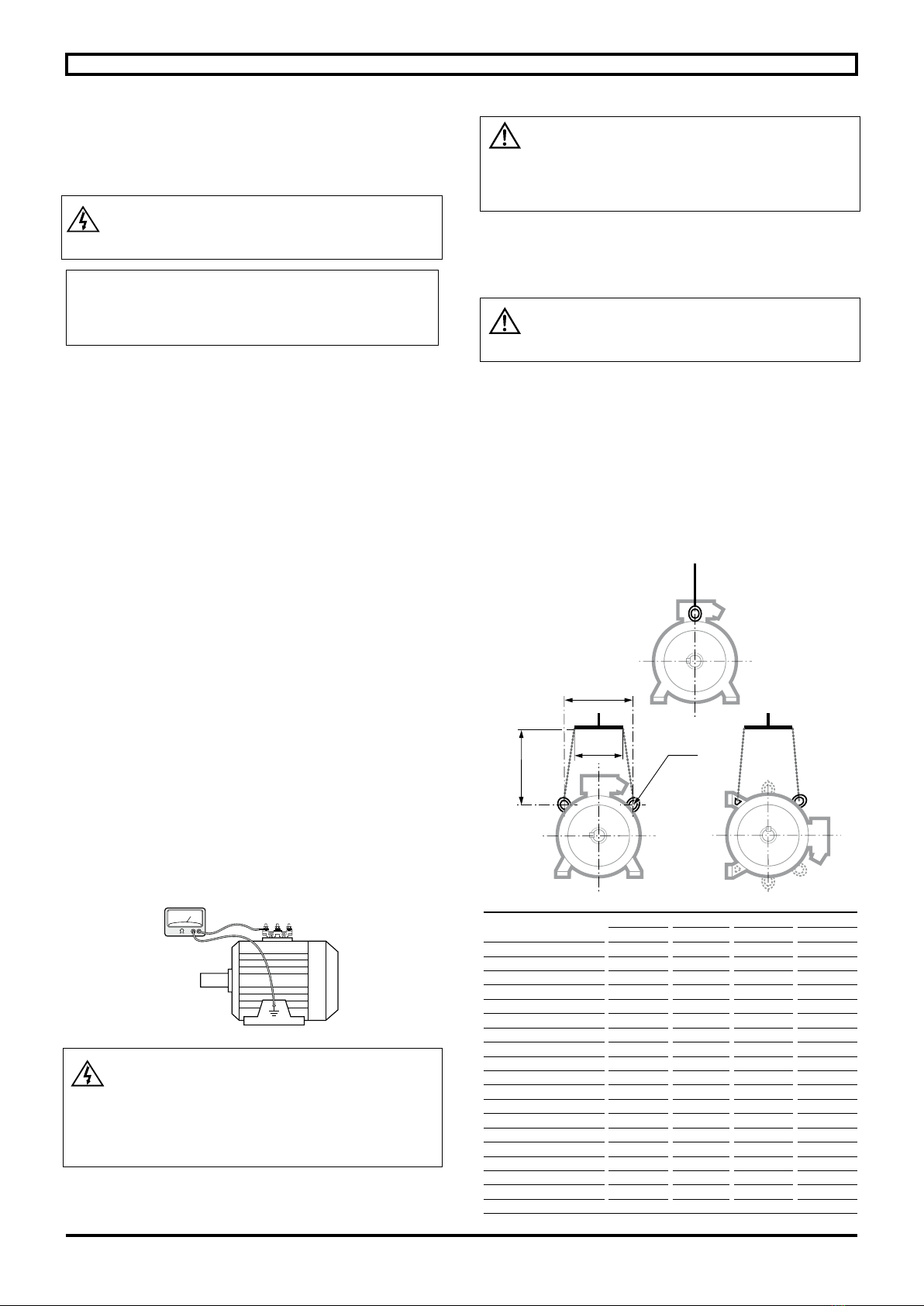
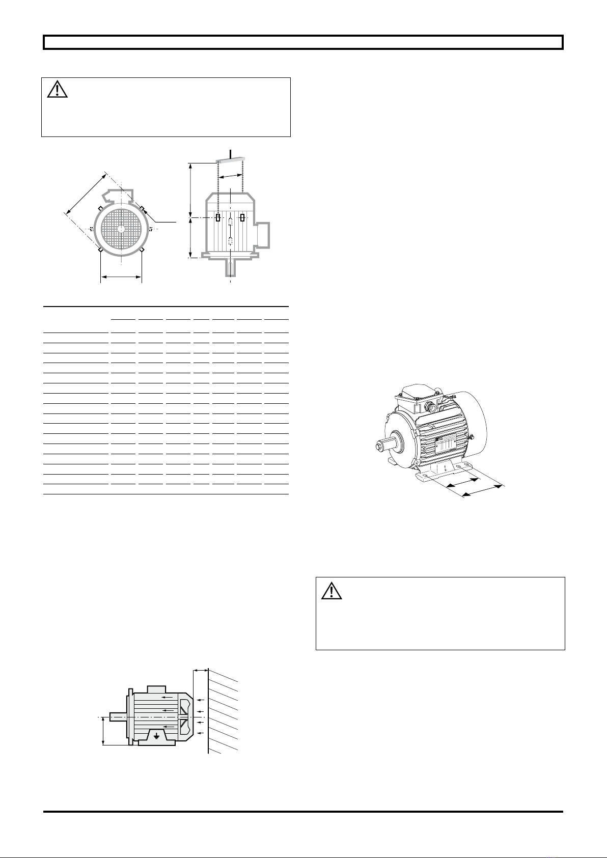
4.1 - Position of the lifting rings ...................................................7
4.2 - Location - ventilation...........................................................8
4.3 - Preparation of the xing support .........................................9
4.4 - Coupling ............................................................................ 9
4.5 - Important information to be taken into consideration during
installation.........................................................................................9
5 - ELECTRICAL PARAMETERS - LIMITING VALUES10
5.1 - Limitation of disturbances caused by starting of motors...10
5.2 - Supply voltage..................................................................10
5.3 - Starting time .....................................................................10
5.4 - Supply with frequency inverter..........................................10
6 - USE...............................................................................10
7 - SPECIAL OPERATING CONDITIONS.......................12
7.1 - Variable speed use ...........................................................13
8 - ADJUSTMENT.............................................................16
9 - MAINS CONNECTION ................................................18
9.1 - Terminal box .....................................................................18
9.2 - Connection to the electrical supply ...................................18
9.3 - Terminal block or isolator connection wiring diagram ........19
9.4 - Direction of rotation...........................................................19
9.5 - Earth terminal and earthing...............................................19
9.6 - Connecting the power supply cables to the terminal block 20
9.7 - Indication of cable gland size and type for 400V rated
supply voltage if drillings required without details of hole diameters
being given .....................................................................................21
9.8 - Admissible number and maximum size of
holes for cable glands per “eb” terminal block .................................21
9.9 - Recommended cable temperatures..................................21
10 - MAINTENANCE.........................................................22
10.1 - General...........................................................................22
10.2 - Corrective maintenance: general....................................23
10.3 - Safety rules.....................................................................24
10.4 - Routine maintenance......................................................24
10.5 - Bearing housing maintenance ........................................25
10.6 - IP Leak tightness of motor ..............................................27
10.7 - Group III paints ...............................................................27
10.8 - Troubleshooting guide ....................................................28
10.9 - Recycling........................................................................28
11 - LSPX MOTORS - ZONE 21....................................... 29
11.1 - LSPX 80 to LSPX 160 MP/LR motors .............................29
11.2 - LSPX 160 M/L, LSPX 180 MT/LR motors ...................... 31
11.3 - LSPX 180 L, LSPX 200, LSPX 225 ST/MT/MR motors ...33
11.4 - LSPX 225 MG, LSPX 250 ME,
LSPX 280 SC/MC/MD/SD motors ................................................. 35
12 - FLSPX MOTORS - ZONE 21 .................................... 37
12.1 - FLSPX 80 to FLSPX 132 motors.................................... 37
12.2 - FLSPX 160 and 180 motors........................................... 39
12.3 - FLSPX 200 and 225 MT/MS motors ...............................41
12.4 - FLSPX 225 M to 280 motors...........................................43
12.5 - FLSPX 315 to 355 LD motors .........................................45
13 - LSES AND FLSES MOTORS - ZONE 22..................48
INDEX
Acceptance.......................................................................................5
Adjustments................................................................................... 16
Alarm - early warning ..................................................................... 11
Assembly......................................................................................... 6
Balancing......................................................................................... 9
Bearing housing xing rods or screws: tightening ...........................23
Bearing housings.................................................................... 24 - 25
Belts............................................................................................... 17
Built-in thermal protection ............................................................... 11
Cable gland.....................................................................................18
Cables ............................................................................................20
Capacitors ......................................................................................24
Connection to mains ............................................................... 18 - 20
Connection wiring diagrams............................................................19
Connection .................................................................................... 20
Corrective maintenance..................................................................23
Coupling .......................................................................................... 9
Coupling sleeves ............................................................................16
Digistart ......................................................................................... 12
Direction of rotation.........................................................................19
Draining o condensation water......................................................24
Earth terminal .................................................................................19
Earth....................................................................................... 12 - 19
Europe Directives ....................................................................... 3 - 5
Fan ...................................................................................................8
Frequency inverter......................................................................... 13
Handling ................................................................................. 7 - 8 - 9
Heaters .......................................................................................... 11
Identication .................................................................................... 5
Inertia ywheel................................................................................16
Insulation ......................................................................................... 7
Lifting ring.........................................................................................7
Location........................................................................................... 8
Lubrication - Grease nipples .........................................6 - 24 - 25 - 26
Lubrication............................................................................... 25 - 26
Nameplate ........................................................................................5
Power supply .......................................................................... 10 - 20
Power ............................................................................................ 10
Protections...................................................................................... 11
Pulleys............................................................................................17
Routine maintenance..................................................................... 24
Spare parts .....................................................................................22
Starting ...........................................................................................10
Storage.............................................................................................6
Terminal box.................................................................................. 18
Terminal plate: tightening of nuts.....................................................19
Tolerances ......................................................................................16
Troubleshooting..............................................................................28
INSTALLATION AND MAINTENANCE - LSPX-FLSPX ZONE 21 - Ex tb – LSES-FLSES ZONE 22 - Ex tc

5
Maintenance and service guide - LSPX-FLSPX ZONE 21 - Ex tb – LSES-FLSES ZONE 22 - Ex tc
5725 en - 2020.02 / c
1 - RECEPTION
This manual or its condensed version is to be given to the end user. In the event of this notice not being translated into the language of the country in which
the motor is used, the distributor is responsible for its translation and for distributing it to end users.
Products to which this manual applies may not be commissioned before the machinery in which they are installed has been declared to conform to the Directives that apply to it.
This equipment and its accessories or associated equipment must be installed by a professional, who is liable for ensuring compliance with all installation rules, decrees,
orders, laws, directives, application memos, standards (where explosive atmospheres are involved, standard IEC-EN 60079-14 as a minimum), regulations, good trade
practices and any other documents relating to the installation site. The professional is also liable for ensuring compliance with the values indicated on the motor information
plate(s), instruction manuals, installation and maintenance manuals and any other document provided by the manufacturer.
Constructions Electriques de Beaucourt (CEB) and LEROY-SOMER cannot be held liable for non-compliance with all or part of the above or with any part of
this manual.
On receipt of your motor, check that it has not suered any damage in transit.
If there are obvious signs of damage, contact the carrier (you may able to claim on their insurance) and after a visual check, turn the motor by hand to detect
any malfunction.
1.1 - Identication and marking
Check that the information shown on the nameplate is compatible with the explosive atmosphere that is present, the utilisation zone and the ambient and surface
temperatures.
Mains supply nameplate Variable speed nameplate Quadratic torque variable speed nameplate
Denition of symbols used on nameplates:
Legal mark of equipment compliance
with the requirements of European Directives.
Special ATEX marking IECEx
:
II 2D or II 3D : ATEX/IECEx marking
Ex tb or tc : Protection mode “dust” envelope
III B or III C : Equipment group
T125°C : Maximum surface temperature
Db or Dc : “dust” EPL level
0080 : Notied organisation INERIS (as II 2D)
INERIS ... X : ATEX attestation no.
IECEx INE... : IECEx certicate no.
Motor symbols:
MOT 3 ~ : Three-phase A.C. motor
FLSES : Motor type
280 : Frame size
M: Housing symbol
4 : 4 poles
B3 : Operating position
No. : Serial number
2017 : Year of manufacture
IM : Operating position symbol
°C : Maximum ambient temperature
Ins. cl. : Winding insulation class
S : Standard operating duty
% : Operating duty
d/h : Number of starts per hour
SF : Duty factor
kg : Weight
DE : Drive end bearing
NDE : Non drive end bearing
g: Quantity of grease to be added per bearing
at each re-lubrication (in g)
h: Interval in hours between re-lubrication
IP : Index of protection
IK : Impact resistance index
m: Maximum operating altitude
V: Supply voltage
Hz : Supply frequency
min-1 : Rated speed of rotation
kW : Rated power
A: Rated current
cos j: Power factor
% : Eciency at 4/4 load
D: Delta coupling
: Star coupling
POLYREX EM 103 : Grease part number for
bearings
Insulated bearing : NDE : Insulated bearing NDE
side
Manufactured by CEB : Equipment manufacturer
EAC Ex : Equipment for explosive atmospheres
certied for Eurasia
cURus : Class F insulation
E068554 for USA and Canada
A : Vibration level code
H: Balancing mode code
NY : Starting requirements code
279 E : Plate reference
Zone ATEX/IECEx
marking
Protection
mode
marking
Maximum
surface
temperature
E.P.L.
level
Index of
protection
min
21 II 2 D Ex tb IIIC T125° Db IP 65
22 II 3 D Ex tc IIIB T125° Dc IP 55
INSTALLATION AND MAINTENANCE - LSPX-FLSPX ZONE 21 - Ex tb – LSES-FLSES ZONE 22 - Ex tc
IE % : Eciency level and eciency,
at rated load and voltage
2/4 : Eciency at 2/4 load
3/4 : Eciency at 3/4 load
Inverter settings PWM : Characteristics for setting the PWM drive to allow temperature class of motor to be met
Motor performance valid for 400V - 50Hz at inverter input : Motor performance for a voltage of 400V - 50 Hz at the
drive input
Duty S9 : Performances given for S9 duty
Min.Fsw : Minimum switching frequency of the drive in kHz
Nmax : Admissible maximum motor speed in rpm
PTC 140°C : PTC sensor type - temperature limit = 140°C
IOL : Admissible over-current = 1.5 x rated current
tOL : Maximum period during which over-current can occur (in secs)
tcool : Minimum duration during which the motor must be at the max of its rated current between
2 over-current events (in secs)
Quadratic torque : Type of torque: quadratic
IVIC : Pulse voltage insulation class code

6
Maintenance and service guide - LSPX-FLSPX ZONE 21 - Ex tb – LSES-FLSES ZONE 22 - Ex tc
5725 en - 2020.02 / c
2 - STORAGE
Prior to commissioning, motors should be stored:
- in a dry location, in their original packaging and protected
from moisture: for relative humidities in excess of 90% the
insulation may fall o very rapidly and around 100% may be
practically zero. Monitor the condition of the rust prevention
protection of unpainted parts. Storage conditions can be
between -40°C and +80°C. For storage in an environment at
between -40°C and -20°C: avoid impacts with the motor
(damage due to the impact resistance of the equipment at
these temperatures).
For very long period storage the motor may be packaged in a
sealed envelope (e.g. thermo-welded plastic) with desiccator
packs inside:
- protected from large and frequent temperature variations in
order to prevent condensation. During the storage periods only
drain plugs should be removed to eliminate condensation
water.
- if the area is subject to vibration, try to reduce the eect of this
vibration by placing the motor on a damping support (rubber
plate or similar).
- turn the rotor a fraction of a turn once a fortnight to prevent the
bearing rings from becoming marked.
- do not remove the rotor locking device (if there are roller
bearings).
Even if the motor has been stored in the correct conditions,
certain checks must be carried out before it is started up:
Greasing
- Motors equipped with permanently greased bearings:
Maximum storage period: 2 years. After this time, replace the
bearings.
- Motors equipped with bearings that can be re-greased:
Storage period
Less than 2
years
The motor may be commissioned if the
recommendations indicated in § 3 are
followed to the letter.
More than
2 years
Bearings must be replaced and bearing
housings (or anges) must be cleaned
and degreased in order to renew the
grease entirely, in accordance with the
information shown on the nameplate
(quantity and type of grease).
Replace shaft passage seals and for
IP66 motors recess seals before starting.
Greases used by LEROY-SOMER:
See nameplates.
Warning! Do not carry out the high voltage test
on auxiliaries.
In the event of the machine being re-painted, the
thickness of the coat must not exceed 2 mm and
0.2 mm for IIC group equipment. Otherwise it must be
anti-static irrespective of its thickness if the motor is II
3G and II 3D.
3 - COMMISSIONING
Before starting users are responsible for checking that the
equipment, the gas (and if relevant dust) group and conditions
of use are compatible.
In all cases, compatibility of the motor and its environ-
ment must be guaranteed before its installation and
also throughout its life.
Electric motors are industrial products.
THEY must therefore be installed by
qualied, experienced and authorized personnel. The
safety of people, animals and property must be
ensured when tting the motors into machines (please
refer to current standards).
3.1 - Protocol for lubrication during
commissioning
Given the “pot” storage lives stated by oil companies and the
transport and storage conditions, the rotation systems of all
motors must be subject to enhanced monitoring during the rst
week of operation.
The aim of this monitoring is to ensure that an oil lm is formed
on the bearing tracks, thus ensuring optimum operation of the
rotation system. Finally, this means that on the one hand
personnel can become familiar with the operation of the
equipment and on the other hand allows any teething troubles
associated with the installation to be identied.
The amount of grease indicated for re-greasing on the
nameplate must be added when topping-up with grease.
Greases must not be mixed. Grease used for top-ups must be
that stated on the nameplate.
If mixed accidentally, bearing housings (or anges) must be
removed and fully cleaned and degreased, and the bearings
must be changed.
In specic terms, the operations to be carried out during
installation are as follows:
• Before installing the motor, top-up with grease and
rotate the motor by hand for ten or so turns.
• After starting the motor (10 min), top up with grease.
• After 24 hours continuous operation, top up with grease.
• After an operating period of 100 to 200 hours, top up with
grease.
• During this starting period (up to 50 hours operation
after the last top up) there must be intensive monitoring.
The bearing housing temperatures and vibration must
be measured frequently.
This data is to be retained by operators. It represents a
databaseandhistorywhichwillbeusefulforfuturemaintenance.
INSTALLATION AND MAINTENANCE - LSPX-FLSPX ZONE 21 - Ex tb – LSES-FLSES ZONE 22 - Ex tc

7
Maintenance and service guide - LSPX-FLSPX ZONE 21 - Ex tb – LSES-FLSES ZONE 22 - Ex tc
5725 en - 2020.02 / c
3.2 - Checking the insulation
Throughout the period required for checking insulation, ensure
that there is no explosive atmosphere present.
Before operating the motor we
recommend checking the insulation between
phases and earth and between phases.
Motors are factory-tted with preventative advice labels
which must kept legible.
Before commissioning remove condensation (see §10.4
- ROUTINE MAINTENANCE)
This check is essential if the motor has been stored for longer
than 6 months or if it has been kept in a damp atmosphere.
This measurement must be carried out using a megohmmeter
at 500 volts DC (do not use a magneto-electric system).
It is better to carry out an initial test at 30 or 50 volts and if the
insulation is greater than 1 megohm, carry out a second test at
500 volts DC for 60 seconds. The insulation value must be at
least 10 megohms in cold state.
If this value cannot be achieved, or routinely if the motor might
have been splashed with water or salt spray, or kept for a long
periodinaveryhumidplace,orifitiscoveredwithcondensation,
it is recommended that the stator be dried for 24 hours in an
oven at a temperature of 110 °C to 120 °C.
If it is not possible to dry the motor in an oven:
- supply the motor, with the rotor immobilised, with a
three-phase AC voltage which is 10% below the rated voltage,
for 12 hours (use an induction regulator or a step-down
transformer with adjustable points).
- or supply it with DC supply with the 3 phases in series, with a
voltage value of 1 to 2% of the rated voltage (use a separate
excitation DC generator or batteries for motors of less than
22 kW).
- NB: The AC current must be monitored using a clamp-on
ammeter, DC using a shunt ammeter. This current must not
exceed 60 % of the rated current.
It is recommended that a thermometer be tted to the motor
frame: if the temperature exceeds 70 °C, reduce the indicated
voltage or current by 5 % of the original value for every 10 °C
dierence.
While it is drying, all the motor orices must be open (terminal
box, drain holes). Before starting replace all plugs so that the
motor exhibits the plated degree of protection. Clean the
orices and plugs before retting them.
Warning! Since the high voltage test was carried
out at the factory before dispatch. If it needs to be
repeated, this should be performed at half the standard
voltage, i.e.: 1/2 (2U+1000V). Check that the capacitive
eect resulting from the high voltage test is eliminated
before connecting the terminals to ground.
For all motors before commissioning:
- remove the dust from the entire machine
- rotate the motor at no load (no mechanical load) for 2 to
5 minutes, checking that there is no abnormal noise.
If there is any abnormal noise, see section 10.
4 - INSTALLATION
4.1 - Position of the lifting rings
The lifting rings are provided for lifting
only the motor. They must not be used to lift the
machine after the motor has been tted to it.
Labour regulations stipulate that all loads over 25 kg must be
tted with lifting devices to facilitate handling.
The overall mass of motors can vary according to their power,
their mounting position and whether the motors are tted with
optional equipment. The actual weight of each Leroy-Somer
motor is indicated on its nameplate. The positions of the lifting
rings and the minimum dimensions of the loading bars are
given below in order to help with preparation for handling the
motors. If these precautions are not followed, there is a risk of
warping or crushing some equipment such as the terminal box,
protective cover or drip cover.
Type Horizontal position
Ae min h min Øt
100 120 200 150 9
112 120 200 150 9
132 160 200 150 9
160 200 160 110 14
180 MR 200 160 110 14
180 L 200 260 150 14
200 270 260 165 14
225 ST/MT/MR 270 260 150 14
225 M 360 265 200 30
225 MG 400 400 500 30
250 MZ 270 260 150 14
250 360 380 200 30
225 MG 400 400 500 30
250 ME/MF 400 400 500 30
280 360 380 500 30
280 SC/MC/MD/SD 400 400 500 30
315 S 310 380 500 17
315 M/L 360 380 500 23
355 310 380 500 23
M
e
A
h
2 x Øt
• Horizontal position
INSTALLATION AND MAINTENANCE - LSPX-FLSPX ZONE 21 - Ex tb – LSES-FLSES ZONE 22 - Ex tc

8
Maintenance and service guide - LSPX-FLSPX ZONE 21 - Ex tb – LSES-FLSES ZONE 22 - Ex tc
5725 en - 2020.02 / c
Motors intended for use in the vertical position
may be delivered on pallets in a horizontal position.
When the motor is pivoted, the shaft must under no
circumstances touch the ground as the bearings could
be irreparably damaged.
View from above Side view
Type Vertical position
C E D N ØS e min* h min
160 320 200 230 2 14 320 350
180 MR 320 200 230 2 14 320 270
180 L 390 265 290 2 14 390 320
200 410 300 295 2 14 410 450
225 ST/MT/MR 410 300 295 2 14 410 450
225 M 480 360 405 4 30 540 350
225 MG 500 400 502 4 30 500 500
250 MZ 410 300 295 2 14 410 450
250 480 360 405 4 30 540 350
250 ME/MF 500 400 502 4 30 500 500
280 S 480 360 485 4 30 590 550
280 M 480 360 585 4 30 590 550
280 SC/MC/MD/SD 500 400 502 4 30 500 500
315 S 590 - 590 2 17 630 550
315 M/L 695 - 765 2 24 695 550
355 755 - 835 2 24 755 550
* If the motor is tted with a drip cover, allow an additional 50 to 100 mm to avoid
damaging it when the load is swung.
4.2 - Location - ventilation
Our motors are cooled in accordance with method IC 411
(standard IEC 60034-6) i.e. “machine cooled by its surface,
using the ambient uid (air) owing along the machine”.
The fan at the non-drive end cools the motor. Air is sucked in
through the grille of a fan cover (which provides protection
against the risk of direct contact with the fan in accordance with
standard IEC 60034-5) and blown along the housing ns to
ensure thermal equilibrium of the motor whatever the direction
of rotation.
The motor is to be installed in an adequately ventilated area,
where the air inlets and exits are free by a value of at least a
quarter of the frame height.
Check that the fan cover bears no impact marks.
Blocking (clogging) the cover grille and the housing ns,
even accidentally, will adversely aect the operation of
the motor and its safety.
With vertical operation with shaft extension downwards, it is
recommended that the motor be equipped with a drip cover to
prevent the entry of any foreign matter.
It is necessary to check that the hot air is not being recycled. If
it is, pipes must be provided for the intake of cold air and
expulsion of hot air, in order to prevent abnormal motor
temperature rise.
In this case, if the air is not circulated by an auxiliary fan, the
dimensions of the pipes must be such that the pressure losses
are negligible compared to those of the motor.
Installation
Possibility of additional external heat
The motor temperature class does not take additional external
heat into account (e.g. pump circulating a hot uid).
The motor must be mounted in the position specied on
the order, on a base which is rigid enough to prevent
distortion and vibration.
Where the motor feet have six xing holes, it is preferable to
use those which correspond to the standard dimensions for the
motor power rating (refer to the asynchronous motors technical
catalogue) or failing this to those shown at B2.
Provide easy access to the terminal box, the condensation
drain plugs and, if appropriate, to the grease nipples.
Use lifting equipment which is compatible with the weight of the
motor (indicated on the nameplate).
When the motor is tted with lifting rings, they are
solely for lifting the motor and must not be used to
lift the whole machine after the motor has been tted to it.
Note 1: When installing a suspended motor, it is essential
to provide protection in case the xing breaks.
Note 2: Never stand on the motor.
e
h
n x ØS
D
E
C
• Vertical position
1/4 H min
H
B
2
B
1
INSTALLATION AND MAINTENANCE - LSPX-FLSPX ZONE 21 - Ex tb – LSES-FLSES ZONE 22 - Ex tc

9
Maintenance and service guide - LSPX-FLSPX ZONE 21 - Ex tb – LSES-FLSES ZONE 22 - Ex tc
5725 en - 2020.02 / c
4.3 - Preparation of the xing support
Installers must pay particular attention to ensuring good
preparation of the motor xing support.
Specic points to be observed:
• All metal supports must have undergone anti-corrosion
treatment.
• The design and the dimensions of the support must
prevent any vibration being transmitted to the motor, as
well as any vibration caused by resonance.
• The support must be level and suciently rigid to
enclose any short-circuit eects.
• The maximum level dierence between the motor xing
feet must not exceed +/- 0.1 mm.
0.1 mm max Level straight-edge
Fixing feet position
4.4 - Coupling
Preparation
Rotate the motor by hand to detect any possible fault due to
handling.
Remove any protection from the shaft extension.
Drain o any condensation water that has formed inside the
motor by removing the plugs from the drain holes. Before
commissioning these plugs must be replaced and the motor
must exhibit the plated degree of protection.
Rotor locking device
For made-to-order motors with roller bearings, remove the
rotor locking device.
In exceptional circumstances when the motor has to be moved
after the coupling device has been tted, the rotor must be re-
immobilized.
Balancing
Rotating machines are balanced in accordance with standard
IEC 34-14:
- half-key when the shaft extension is marked H.
When specically requested, balancing may be carried out:
- no key when the shaft extension is marked N,
- full key when the shaft extension is marked F,
any coupling element (pulley, coupling sleeve, slip-ring, etc.)
must therefore be balanced accordingly.
Motor with 2 shaft extensions:
If the second shaft extension is not used, in order to
conform to the balancing class the half-key or key must be
rmly tted in its groove so that it is not ejected during
rotation (H or F balancing) and to protect it against direct
contact.
4.5 - Important information to be taken
into consideration during installation
- Equipment to which this manual applies may not be
commissioned before the machinery in which it is installed has
been declared to conform to the Directives that apply to it.
- When motors are supplied by suitable electronic converters
and/or controlled by electronic command and control devices,
they must be installed by a professional who will be responsible
for ensuring compliance with the electromagnetic compatibility
regulations for the country in which the product is installed.
- As standard the motors’ impact resistance corresponds to
“low” mechanical risk, therefore they must be installed in a low
mechanical risk environment.
- All unused orices must be blocked o using Ex threaded
plugs.
- All accessories (cable glands, plugs etc.) cited in this notice
must be of a type that is attested or certied for the group, the
application (gas and/or dust) and the temperature class which
correspond as a minimum to those for the location of the
equipment (see the information on the nameplate). They are
correctlytightened ontotheir support.A‘’KLINGERSILC-4400’’
bre seal, for example, is placed between the cable glands, the
plugs and their support. Cable glands must be appropriate for
the supply cable and any auxiliary cables. The cables are
correctly gripped in the cable glands.
Fitting must comply with the requirements of their instructions
for use.
- The assembly of all these components must ensure the mode
of protection (Ex) and the protection indices (IP, IK) specied
on the nameplates.
- All threaded components must be fully tightened.
INSTALLATION AND MAINTENANCE - LSPX-FLSPX ZONE 21 - Ex tb – LSES-FLSES ZONE 22 - Ex tc

10
Maintenance and service guide - LSPX-FLSPX ZONE 21 - Ex tb – LSES-FLSES ZONE 22 - Ex tc
5725 en - 2020.02 / c
5 - ELECTRICAL PARAMETRES -
LIMITING VALUES
5.1 - Limitation of disturbances caused
by starting of motors
To ensure preservation of the installation, any signicant
overheating of pipework must be avoided whilst ensuring that
the protective devices do not intervene during starting.
Disturbances resulting in the operation of other equipment
connected to the same source are due to the voltage drop
caused by the current demand on starting (multiple of the
current passing through the motor at full load (about 7) see
LEROY-SOMER asynchronous motors technical catalogue).
Even though networks are increasingly capable of allowing
direct starting, current demand must be reduced for certain
installations.
Jerk-free operation and smooth starting mean that the driven
machinery will be easier to use and have a longer operating
life.
The two essential parameters for starting squirrel cage
synchronous motors are:
- starting torque
- starting current.
The starting torque and the resistive torque determine the
starting time.
Depending on the driven load, the torque and current can be
altered to match the starting options of the machine and to
match the supply options.
The ve essential modes are:
- D.O.L. starting,
- star/delta starting,
- soft starting with autotransformer,
- soft starting with resistors,
- electronic starting.
Electronic starting modes control the voltage at the motor
terminals throughout the entire starting phase, giving very
gradual smooth starting.
5.2 - Supply voltage
The rated voltage is indicated on the nameplate.
5.3 - Starting times
Starting times must remain within the limits indicated below on
condition that there are 6 or less starts during one hour.
Three successive cold starts and two consecutive hot starts
are allowed.
Permissible motor starting time as a function of the ratio ID/ IN.
In the event of frequent or dicult startup conditions, equip
motors with thermal protection devices (see § 6 - USE).
5.4 - Supply with frequency inverter
See § 7.1.
25
20
15
Time (secs)
10
5567Id/In 8 9 10
Hot startingCold starting
INSTALLATION AND MAINTENANCE - LSPX-FLSPX ZONE 21 - Ex tb – LSES-FLSES ZONE 22 - Ex tc
6 - USE
Thermal protection devices (see § 8) and heaters
Type Operating
principle
Operating
curve
Switch
rating (A) Protection provided Mounting
Number of devices*
Thermal protection
on opening
PTO
bimetallic strip, indirectly
heated, with normally
open contact (0)
I
OTNF
T2.5 at 250 V
with cos j0.4
general surveillance
for non-transient
overloads
Installed in the
control circuit
2 or 3 in series
Normally closed
thermal protection
PTF
bimetallic strip, indirectly
heated, with normally
closed (F) contact
I
FTNF
T2.5 at 250 V
with cos j0.4
general surveillance
for non-transient
overloads
Installed in the
control circuit
2 or 3 in parallel

11
Maintenance and service guide - LSPX-FLSPX ZONE 21 - Ex tb – LSES-FLSES ZONE 22 - Ex tc
5725 en - 2020.02 / c
Positive temperature
coecient thermistor
PTC
Non-linear variable
resistor,
indirectly heated
R
TNF
T0
general surveillance
for transient overloads
Mounted with associated
relay in
control circuit
3 in series
Thermocouples
T (T<150°C)
Constantan Copper
K(T<1000°C)
Copper Copper-
Nickel
Peltier eect
V
T0
high precision
of hot spots at
regular intervals
Mounted in control panels
with associated reading
equipment
(or recorder)
1 per hot spot
Platinum
temperature
sensor
PT 100
Linear variable
resistor
indirectly heated
R
T0
high precision
continuous surveil-
lance
of key hot spots
Mounted in control panels
with associated reading
equipment
(or recorder)
1 per hot spot
- NRT: nominal running temperature.
- The NRTs are chosen according to the position of the sensor in the motor and the temperature rise class.
* The number of devices relates to the winding protection.
Alarm and early warning
All protective equipment can be backed up by another type of
protection (with dierent NRTs): the rst device will then act as
an early warning (light or sound signals given without shutting
down the power circuits), and the second device will be the
alarm (shutting down the power circuits).
Protection against condensation: space heaters
Marking: 1 red label
A glass bre exible resistor is xed on 1 or 2 coil end turns.
This resistor heats the machines when stopped and thus
prevents condensation inside the machines.
Power supply: 230 V single-phase unless otherwise specied
by the customer.
Recommended for use when ambient temperatures ≤ 20°C. In
allcasesthepowerdissipatedmustensurethatthetemperature
classication of the motor is observed.
Heaters or heating using the introduction of ac voltage must
only be used when the motor is de-energised and cold.
The drain plugs at the bottom of the motor must be opened
every six months or so. They must be retted in place and the
motor degree of protection guaranteed.
Thermo-magnetic protection
Motors are protected by the magneto-thermal device placed
between the isolating switch and the motor. These protection
devices provide total protection of the motor against non-
transient overloads.
This device may be accompanied by fused circuit breakers.
Built-in direct thermal protections
For low rated currents, bimetallic strip-type protection may be
used. The line current passes through the strip, which shuts
down or restores the supply circuit as necessary. The design
of this type of protection allows for manual or automatic reset.
Built-in indirect thermal protection
Motors may be equipped with thermal sensors as an option.
These sensors follow the temperature changes at “hot spots”:
- overload detection,
- cooling check,
- monitoring characteristic points for maintenance of
the installation.
It must be emphasized that under no circumstances can these
sensors be used to carry out direct regulation of the motor
operating cycles.
The associated equipment must cause the motor to stop when
the values of the thermal protection indicated below are
reached
Thermal protection
In-line protection
Adjusting the thermal protection (see § 6)
Itmustbesettothecurrentvalueshownonthemotornameplate
for the voltage and frequency of the connected supply.
Temperature sensor operating thresholds:
Maximum
temperature of
dust motor surface
Maximum value of the
winding sensor and of
adjustment of associated
equipment
Maximum value of the
bearing housing sensor and
of adjustment of associated
equipment
Frame size (F)LSPX
80 to 250
(F)LSPX
280 to 355
(F)LSPX
80 to 250
(F)LSPX
280 to 355
85°C 120°C 100°C 90°C 70°C
100°C 120°C 110°C 90°C 90°C
125°C 130°C 140°C 110°C 110°C
135°C 130°C 140°C 110°C 110°C
145°C 130°C 140°C 110°C 110°C
Electrical characteristics of sensors and thermocouples:
* I max = 5A.
* U max :
* for PT100 at 0°C = 2.5 V * for PTO/PTF = 7.5 V
* for PTC = 7.5 V * for thermocouple = 7.5 V
In order to meet requirements for maximum surface
temperature, the thermal sensors tted to the
motor must be connected to a device which causes the
supply to the motor to be cut o when the operating
thresholds dened above are reached.
INSTALLATION AND MAINTENANCE - LSPX-FLSPX ZONE 21 - Ex tb – LSES-FLSES ZONE 22 - Ex tc

12
Maintenance and service guide - LSPX-FLSPX ZONE 21 - Ex tb – LSES-FLSES ZONE 22 - Ex tc
5725 en - 2020.02 / c
7 - SPECIALOPERATINGCONDITIONS
- Installation zones
Our motors oer an IP 65 (or IP 55-zone 22) degree of protection
andweguarantee theirsurface temperature.They areintended
for use in dusty explosive atmospheres of group II - Category
2 (IP 65-zone 21) or Category 3 (IP 55-zone 22).
- Employee safety
Protect all rotating devices before power-up.
If a motor is started up without a coupling device having been
tted, carefully immobilize the key in its housing.
All measures must be taken to provide protection against risks
associated with rotation of components (sleeve, pulley, belts
etc.).
Beware of backdriving when the motor is switched o.
Appropriate precautions must be taken:
- pumps, install a non-return valve, for example.
- Thermal protection (see § 6 & 8)
Motors for dicult starting conditions or with frequent starting
must be equipped with thermal protection.
- Heaters (see § 6)
Heaters must only be in service when the motor is stopped and
cold. Recommended for use when ambient temperatures ≤
20°C. In all cases the power dissipated must ensure that the
temperature classication of the motor is observed.
- Temperatures: storage and ambient
Note: Ta= ambient temperatures
If the motor has been stored at a temperature below -10 °C,
heat the motor (see § 3) and turn the shaft by hand before
operating the machine.
If the motor is to be used at a temperature lower than -25 °C, it
must not be tted with a sensor. It can be tted with
thermocouples.
As standard construction, our motors are designed to operate
at temperatures between -20 °C and 40 °C.
If Ta < -25 °C, shaft passage seals must be made of silicone and
the fan made of metal.
If Ta < -25 °C or (and) if 50 °C < Ta ≤ 60 °C, terminal box face
seals must be made of silicone.
- Surface temperature
As standard, the maximum surface temperature of our motors
is 125 °C with a maximum ambient temperature ≤ 40 °C.
Without adaptation of the motor the maximum surface
temperature will be:
• 135 °C if 40 °C ≤ Ta ≤ 50 °C
• 145 °C if 50 °C ≤ Ta ≤ 60 °C
- Connection
Particular attention must be paid to the information on the
nameplate in order to choose the correct type of connection for
the supply voltage.
When motors are equipped with one or more auxiliary
connectionboxes, it can only withstandalow risk of mechanical
damage, and users must provide additional protection if there
is a high risk.
Similarly the protection system and the supply cables (the
voltage drop during the starting phase must be less than 3%)
are to be selected according to the characteristics marked on
the nameplate.
- Earthing
The motor must be earthed in accordance with the applicable
regulations (protection of workers).
An external terminal on the frame is used for eective earth
connection of equipotential links. This terminal must be
prevented from working itself loose.
- Leak tightness
Monitor the condition of all seals and replace them periodically
if necessary (Once a year at least for Ex tb motors).
At the shaft passages, take care not to damage the seals in
contact with the keys and shoulders.
After removing drain plugs, ret them in place in order to ensure
the plated degree of protection of the motor. Replace the seals
thatareremovedusingnewsealswiththesamecharacteristics.
Clean the orices and plugs before retting them. Whenever
removed it is recommended that once a year (depending on
the application) you replace seals (shaft passages, bearing
housing recesses, terminal box cover etc.) using new seals
with the same characteristics after cleaning the components.
Shaft passage seals must be tted using the same type of
grease as the bearings.
IP6X thread leak tightness (mandatory if Ex tb marking)
may be enhanced using grease.
- Shock resistance
The motor can withstand a low mechanical impact (IK 08
according to EN 50102). The user must provide additional
protection if there is a risk of signicant mechanical shock.
Note: option IK 10 may be ordered.
- LEROY - SOMER “Digistart” electronic starter
This is micro-controlled multi-function electronic system,
which is used with all squirrel-cage asynchronous three-phase
motors.
It ensures smooth starting of the motor with:
- reduced starting current,
- smooth jerk-free acceleration achieved by controlling the
current in the motor.
After starting, the DIGISTART carries out additional motor
management functions in its other operating phases: steady
state and slowing.
- Models from 18 to 1600 A
- Power supply: 220 to 700 V - 50/60 Hz
The DIGISTART is low-cost to install, and only an additional
switch and fuses are required.
The “Digistart” electronic starter associated with the
motor must be installed outside the hazardous zone
(zones 20, 21, 22).
- Contactors - Main switches
Under all circumstances contactors, main switches etc. must
be installed and connected in a panel which oers a degree of
protection and a surface temperature compatible with the
installation zone, or outside the hazardous zone (zones 20, 21
and 22).
INSTALLATION AND MAINTENANCE - LSPX-FLSPX ZONE 21 - Ex tb – LSES-FLSES ZONE 22 - Ex tc

13
Maintenance and service guide - LSPX-FLSPX ZONE 21 - Ex tb – LSES-FLSES ZONE 22 - Ex tc
5725 en - 2020.02 / c
- Auxiliary fan
When the motor is equipped with auxiliary or forced ventilation
a device must prevent the main motor form operating in the
absence of ventilation.
- Fitting sensors or accessories
In the event that sensors (vibration sensors for example) or
accessories (pulse generators for example) are tted, these
must be connected in a panel.All these accessories (as well as
the panel if it not located outside the explosive atmosphere)
must be of a type that is certied or attested for the group, the
application (Gas or Gas and dust) and the temperature class
which corresponds at least to that of the motor. Fitting must
comply with the requirements of their instructions for use.
The sensors must exhibit an IP 65 (zone 21) or IP 55 (zone 22)
degree of protection at least.
- Noise level
Most (F)LSPX / (F)LSES zone 22 motors have an acoustic
pressure level of less than 80 dB(A) (+/- 3dB) at 50Hz.
The values for each motor are given in our technical catalogue.
When the motors operate using a drive, please contact us for
the noise levels.
7.1 - Variable speed use
7.1.1 - General
Drive control by a frequency inverter can in fact result in an
increase in the machine temperature rise, due to a signicantly
lower supply voltage than on the mains, additional losses
related to the wave form produced by the drive (PWM) and the
reduction in speed of the cooling fan.
Standard IEC 60034-17 describes numerous good practices
for all types of electric motor, however since this is Leroy-
Somers’ area of specialist expertise, we describe the best
ways to deal with variable speed in the section below.
The homologation conditions of our safety motors allow them
to operate on frequency drives on condition that the required
precautions are taken to ensure that under all circumstances
there is compliance with the temperature class marked on the
nameplate.
Drive control using a frequency inverter results in an increase
in the machine temperature rise, primarily as the result of a
reduction in cooling fan speed and a supply voltage which is
signicantly lower than that of the network. Consequently a
reduction must generally be made in the rated power of the
motor. Derating tables have been produced by our design
bureau based on under-load tests on platforms, and on the
requirements of IEC 60034-17. Depending on the application,
on the desired speed range and the torque prole of the driven
machine, Leroy-Somer will select the most suitable safety
motor. The drive, if of a type not designed for operation in an
explosive zone, must be located in a non-explosive zone.
In certain cases, the use of forced ventilation (where the fan is
driven by an auxiliary motor whose type has been certied)
may prove necessary. For small motors (frame height less than
160), the standard self-ventilated cooling mode (IC411) is
nevertheless to be preferred.
A device for measuring the actual speed of the motor using an
incremental or absolute encoder which is ATEX certied, may
also be installed at the rear of most of our safety motors.
ATEX motors supplied through a frequency inverter are
equipped with thermal protective devices in the winding.
These must operate independently of measuring and
control devices required for operation. Our derating
tables are based on a drive supply whose switching
frequency is equal to or greater than 3 kHz.
ADAPTATION OF MOTORS
A motor is always characterised by the following parameters,
which depend on the design:
- temperature class
- voltage range
- frequency range
- thermal reserve
CHANGES IN MOTOR PERFORMANCE
When power is supplied by a drive, changes are observed in
the above parameters due to certain phenomena:
- voltage drops in the drive components
- current increase in proportion with the decrease in voltage
- dierence in motor power supply according to the type of
control (ux vector or U/f)
The main consequence is an increase in the motor current
resulting in increased copper losses and therefore a higher
temperature rise in the winding (even at 50 Hz).
Reducing the speed leads to a reduction in air ow and hence
a reduction in cooling eciency, and as a result the motor
temperature rise will increase again.
Conversely, in prolonged operation at high speed, the fan may
make excessive noise, and it is advisable to install a forced
ventilation system.
Above the synchronous speed, the iron losses increase
and hence cause further temperature rise in the motor.
The type of control mode inuences temperature rise in the
motor:
- A U/f ratio gives the fundamental voltage maximum at 50 Hz
but requires
more current at low speed to obtain a high starting torque and
therefore generates a temperature rise at low speed when the
motor is poorly ventilated.
- Flux vector control requires less current at low speed while
providing signicant torque but regulates the voltage at 50 Hz
and causes a voltage drop at the motor terminals, therefore
requiring more current at the same power.
The temperature classication was realised with an IGBT
drivesupply and PWM waveform, minswitching frequency
= 3kHz, U/f constant open loop.
INSTALLATION AND MAINTENANCE - LSPX-FLSPX ZONE 21 - Ex tb – LSES-FLSES ZONE 22 - Ex tc

14
Maintenance and service guide - LSPX-FLSPX ZONE 21 - Ex tb – LSES-FLSES ZONE 22 - Ex tc
5725 en - 2020.02 / c
CONSEQUENCES OF POWER SUPPLIED BY DRIVES
When power is supplied to the motor by a variable speed drive
with diode rectier, this causes a voltage drop (~5%).
Some PWM techniques can be used to limit this voltage drop
(~2%), to the detriment of the machine temperature rise
(injection of harmonics of orders 5 and 7).
The non-sinusoidal signal (PWM) provided by the drive
generates voltage peaks at the winding terminals due to the
signicant voltage variations relating to switching of the IGBTs
(also called dV/dt). Repeated overvoltages can eventually
damage the windings depending on their value and/or the
motor design.
The value of the voltage peaks is proportional to the supply
voltage.
This value can exceed the limit voltage for the windings which
is related to the wire grade, the impregnation type and the
insulation that may or may not be present in the slot bottoms or
between phases.
Another reason for attaining high voltage values is when
regeneration phenomena occur in the case of a driving load,
hence the need to prioritise freewheel stops or stops that follow
the longest permissible ramp.
7.1.2 - Minimum recommendations
The specic instructions given in the specic instruction
manuals must be followed if a drive is used. In particular the
following minimum requirements must be observed:
- Check that the drive switching frequency is 3 kHz minimum.
- Check that the motor has a second nameplate which give the
maximum characteristics and performance levels of the motor
during its use at variable speed.
- The reference voltage, usually 400V 50 Hz, is given on the
motor nameplate. The drive must deliver a constant voltage/
frequency ratio.
- Programme the maximum current value as well as the min
and max frequency values shown on the second nameplate of
the motor into the drive.
- Connect all the temperature sensors present on the motor
(windings and, if relevant, bearing housings) to safety devices
which are independent of those used for operation under
normal conditions.
Drives and sensor connection components must
be located outside hazardous zones (zones 0, 1, 2,
20, 21 and 22).
7.1.3 - Special conditions for safe use
- As standard the motors’ impact resistance corresponds to
“low” mechanical risk, therefore they must be installed in a low
mechanical risk environment.
- The motor must be equipped with 3 thermal sensors (1 per
phase) placed in or on the stator connection side winding
heads (all frame sizes) and on the front bearing housing (from
frame size 355) in the following cases:
- motor supplied by frequency inverter
- motor in a sucient, non self-ventilated airow (IC418)
- motor adapted to no longer be self-ventilated (IC410)
- motor equipped with a backstop
- motor equipped with an auxiliary fan (IC416A) or radial
fan (IC416R)
The thermal protection devices must be connected
to a device which de-energises the motor when the
setting value is reached and before the maximum surface
temperature T° of the motor reaches the classication
temperature shown on the nameplate.
- Whenthemotorisequippedwithauxiliaryorforcedventilation
(IC416) a device must prevent the main motor form operating
in the absence of ventilation. Stopping the auxiliary motor must
cause the main motor to stop.
- Heaters must only be supplied when there is no supply to the
motor and the latter is cold. Their use is recommended for
ambient temperatures of less than -20°C.
- Supply voltages and frequencies must comply with those
stated on the motor nameplate.
- The frequency range stated on the motor nameplate must be
strictly observed.
- In the event of several motors being supplied by the same
drive, for safety reasons individual protection must be provided
on each motor outlet (e.g. thermal relay).
- The specic instructions given in the specic instruction
manuals must be followed if a drive is used.
- Cable glands and components must be compatible with the
protection mode used for the connection portion. Alternatively,
with integral cables, the motor connection must be made
outside the explosive atmosphere or in a housing protected by
a recognised protection method which is suitable for this use.
- The degree of protection of the motor, of its main connection
housing and of any auxiliary connection box(es) is:
* for zone 21: IP65 - IK08
* for zone 22: IP55 - IK08
The user must provide additional protection if there is a high
risk.
- Variable speed
The use of these motors with a frequency or voltage inverter
supply requires specic precautions for use:
The reference voltage (inverter output or
motor input) is 400 V at 50 Hz; the drive must supply
a constant voltage/frequency to the motor.
The voltage and supply frequency range specied
by the motor nameplate must be rigorously
observed.
Drives and sensor connection components must
be located outside hazardous zones (zones 20, 21
and 22).
INSTALLATION AND MAINTENANCE - LSPX-FLSPX ZONE 21 - Ex tb – LSES-FLSES ZONE 22 - Ex tc

15
Maintenance and service guide - LSPX-FLSPX ZONE 21 - Ex tb – LSES-FLSES ZONE 22 - Ex tc
5725 en - 2020.02 / c
When motors are supplied through a separate frequency
inverter, or are used in a sucient air-ow or if necessary
adapted so as to no longer be self-ventilated or equipped with
a backstop, they must be equipped with thermal sensors in the
windings (all frame sizes), on the front bearing housing (from
frame size 355 and above) and if relevant on the rear bearing
housing.
When the motor is equipped with auxiliary or forced ventilation
a device must prevent the main motor form operating in the
absence of ventilation.
The specic instructions given in the specic instruction
manuals must be followed if a drive is used.
In the event of several motors being supplied by the same
drive, for safety reasons individual protection must be provided
on each motor outlet (e.g. thermal relay).
Any changes to settings must be made by trained and
authorised personnel and in accordance with this guide.
- Operating position
When the motor is used in a position other than horizontally or
vertically, the front bearing housing must be equipped with a
thermal sensor and the shaft extension away from the fan
aligned downwards.
7.1.4 - Extreme operating conditions and
specic features
MOTOR CONNECTIONS
Leroy-Somer do not recommend any specic connections for
applications operating with a single motor on a single drive.
TRANSIENT OVERLOADS
Drives are designed to withstand transient overload.
When the overload values are too high, the system will
automatically shut down. Leroy-Somer motors are designed to
withstand these overloads, however in the event of very
repetitive operation we still recommend use of a temperature
sensor in the winding of the motor.
STARTING TORQUE AND CURRENT
Thanks to advances in control electronics, the torque available
when the motor is switched on can be adjusted to a value
between the rated torque and the variable speed drive
breakdown torque.
The starting current will be directly related to the torque (120 or
180%).
ADJUSTING THE SWITCHING FREQUENCY
The variable speed drive switching frequency has an impact
on losses in the motor and the drive, on the acoustic noise and
the torque ripple.
A low switching frequency has an adverse eect on temperature
rise in motors.
Leroy-Somer recommends a drive switching frequency of 3
kHz minimum.
In addition, a high switching frequency optimises the acoustic
noise and torque ripple level.
OPERATION AT SPEEDS HIGHER THAN THOSE
ASSIGNED BY THE MAINS FREQUENCIES
There are risks associated with the use of asynchronous
motors at high speed (speed higher than 3600 rpm):
• the cage may be damaged,
• bearing life may be impaired,
• there may be increased vibration,
• etc.
Motors are designed to operate at the speeds shown on the
nameplate (do not exceed the maximum speeds stated in our
technical catalogues).
When high-speed motors are used, they often need to be
adapted, and an in- depth mechanical and electrical design
exercise is needed.
CHOICE OF MOTOR
There are two possibilities:
a - The frequency inverter is not supplied by Leroy-Somer.
All the motors in this catalogue can be used with a frequency
inverter.
Depending on the application, motors will need to be derated
by around 10% compared to the motor operating curves in
order to guarantee that motors will not be damaged.
b - The frequency inverter is supplied by Leroy-Somer
As these motor-drive assemblies have been specically
designed for use in combination, excellent performance is
guaranteed.
7.1.5 - Winding insulation and
recommendations relating to the mechanism
of rotation
The insulation systems used for Leroy-Somer motors and
recommendations for protection systems on the mechanisms
of rotation are indicated in our good practice guide ref. 5626.
7.1.6 - Nameplates on motors operating with
variable speed drives
The performance levels of motors operating using variable
speed drives, shown on the VV nameplate, are values obtained
with PWM supplies, with 360V at the motor terminals, in
continuous operation.
That is, for the following two cases:
• 400V rated voltage before drive + drive voltage drop
of 40V.
• A – 10% + drive with no voltage drop.
Please contact us for other cases.
Some applications require special construction specications:
- Do not use a motor for lifting that is not rated S3 or S4.
- Do not use the motor with a dierent duty type from that on the
nameplate and in particular not in lifting applications.
INSTALLATION AND MAINTENANCE - LSPX-FLSPX ZONE 21 - Ex tb – LSES-FLSES ZONE 22 - Ex tc

16
Maintenance and service guide - LSPX-FLSPX ZONE 21 - Ex tb – LSES-FLSES ZONE 22 - Ex tc
5725 en - 2020.02 / c
INSTALLATION AND MAINTENANCE - LSPX-FLSPX ZONE 21 - Ex tb – LSES-FLSES ZONE 22 - Ex tc
8 - ADJUSTMENT
Tolerances and adjustments
Standard tolerances are applicable to the mechanical
characteristic values given in our catalogues. They comply
fully with the requirements of standard IEC 60072-1.
-Adhere strictly to the instructions provided by the transmission
device supplier.
- Avoid impacts which could damage the bearings.
Use a screw device and grease the tapped hole of the shaft
extension with a special lubricant (e.g. molykote grease) to
make it easier to t the coupling.
The hub of the transmission device must be :
- Fully in contact with the shoulder of the shaft or, if this is
missing, hard up against the metal stop ring to form a labyrinth
seal and thus lock the bearing in place (do not crush the seal);
- longer than the shaft extension (by 2 to 3 mm) so that it can
be tightened using a screw and washer. If it is not, a spacer ring
must be inserted without cutting the key (if this ring is large, it
must be balanced).
Supported Supported
on the shaft shoulder on the stop ring
In the case of a second shaft extension, it must only be used
for direct coupling and the same recommendations must be
followed.
The 2nd shaft extension may also be smaller
than the main shaft extension and may under no
circumstances supply torques greater than half the
rated torque.
Inertia ywheels must not be mounted directly onto the shaft
extension, but installed between bearing housings and
connected by a coupling sleeve.
Direct connection to the machine
When mounted directly on the motor shaft extension of the
moving device (pump or fan turbine), check that this device is
perfectly balanced and that the radial force and the axial thrust
are within the limits indicated in the catalogue for bearing
performance.
Direct connection using a coupling sleeve
Selection of the coupling sleeve should take account of the
rated torque to be transmitted and the safety factor dependent
on the starting conditions for the electric motor.
The machines must be carefully aligned, so that any lack of
concentricity and parallelism in the two coupling halves is
compatible with the coupling sleeve manufacturer’s
recommendations.
The two parts of the coupling sleeve should be temporarily
assembled to make it easier to alter their relative position.
Adjust the parallel plane of both shafts using a gauge. Measure
the distance between the two coupling surfaces at one point on
the circumference. Rotate them 90°, 180° and 270° in relation
to this initial position, and measure each time. The dierence
between the two extreme values of dimension “x” must not
exceed 0.05 mm for standard couplings.
To perfect this adjustment and at the same time check the
concentricity of the two shafts, t 2 gauges as shown in the
diagram and slowly turn both shafts.
The deviations registered by either shaft will indicate the need
for an axial or radial adjustment if the deviation exceeds
0.05 mm.
Direct connection using a rigid coupling
The two shafts must be aligned so as to adhere to the coupling
sleeve manufacturer’s tolerances.
Maintain the minimum distance between the shaft extensions
to allow for expansion of the motor shaft and the load shaft.
A
Ø
Ø (mm) A (mm)
min
9 to 55 1
60 1.5
65 1.5
75 2
80 2
x

17
Maintenance and service guide - LSPX-FLSPX ZONE 21 - Ex tb – LSES-FLSES ZONE 22 - Ex tc
5725 en - 2020.02 / c
Transmission via belt pulleys
The user chooses the diameter of the pulleys.
Castironpulleyswithadiameterover315arenotrecommended
for rotation speeds of 3,000 rpm.
Flat belts cannot be used for rotation speeds of 3,000 rpm or
more.
Positioning the belts
The belts must be anti-static and ame
propagation must only occur with diculty.
So that the belts can be correctly positioned, allow for possible
adjustment of approximately 3 % with respect to the calculated
distance E.
Force must never be used when tting the belts.
For notched belts, position the notches in the pulley grooves.
Aligning the pulleys
Check that the motor shaft is completely parallel with that of the
receiving pulley.
Protect all rotating devices before power-up.
Adjusting the belt tension
The tension of the belts must be adjusted very carefully in
accordance with the recommendations of the belt supplier and
the calculations made when the product was specied.
Reminder:
-tension toogreat =unnecessary forceonthebearinghousings
which could lead to premature wear of the bearing unit (bearing
housing-bearings) and eventually break the shaft;
- too little tension = vibration (wearing of the bearing unit).
Fixed distance between centres:
Place a belt tensioning pulley on the slack side of the belts:
- smooth pulley on the outside of the belt;
- grooved pulley on the inside of the belts when using V-belts.
Adjustable distance between centres:
The motor is usually mounted on slide rails, which enables
optimum adjustment of the pulley alignment and the belt
tension.
Place the slide rails on a perfectly horizontal baseplate.
The lengthways position of the slide rails is determined by the
length of the belt, and the crossways position by the pulley of
the machine being driven.
Mount the slide rails rmly with the tension screws in the
direction shown in the diagram (the slide rail screw on the belt
side between the motor and the machine being driven).
Fix the slide rails to the baseplate and adjust the belt tension
as before.
E
Tension screw
Tension screw
INSTALLATION AND MAINTENANCE - LSPX-FLSPX ZONE 21 - Ex tb – LSES-FLSES ZONE 22 - Ex tc

18
Maintenance and service guide - LSPX-FLSPX ZONE 21 - Ex tb – LSES-FLSES ZONE 22 - Ex tc
5725 en - 2020.02 / c
INSTALLATION AND MAINTENANCE - LSPX-FLSPX ZONE 21 - Ex tb – LSES-FLSES ZONE 22 - Ex tc
9 - MAINS CONNECTION
9.1 - Terminal box
If the threaded hole(s) of the orice(s) intended to receive
cable gland(s) or conduit(s) have/has ISO metric threads,
there is no specic marking present on the motor. If the type of
thread is dierent or mixed, the type(s) are marked on the
equipment.
It is placed as standard on top and at the front of the motor. It
oers an IP 65 degree of protection and is equipped with cable
glands.
Caution: the position of the terminal box cannot easily be
changed, even with anged motors, as the condensation drain
holes (if present) must be at the bottom.
Cable gland
The standard position of the cable gland is on the right when
viewed from the drive end (1).
If the special position of the cable gland has not been correctly
specied on the order, or is no longer suitable, the symmetrical
construction of the terminal box enables it to be turned in 4
directions except for position (2) for motors with smooth holed
anges (B5).
A cable gland must never open upwards.
Check that the incoming cable bend radius prevents water
entering via the cable gland.
Terminal box positions Cable gland positions
Cable size
Matchthe cable glandandanyassociatedexpander
or reducer to the diameter of the cable used, in
accordance with the specic instructions for the cable
gland.
In order to maintain the motor’s original IP protection, it
is essential to ensure leak-tightness between the rubber
ring and the cable by tightening the cable gland correctly
(so that it cannot be unscrewed by hand).
Unused cable glands must be replaced by threaded
plugs.
Unused orices must also be blocked o using threaded
plugs. It is essential to ensure that the tting of cable
glands or blanking devices is carried out with a silicone
or polyurethane sealant seal being made between the
cable glands, the plugs, the reducers and (or) expanders,
the support or the box body.
Installers are responsible for ensuring that the
leak-tightness of cable passages is achieved (see
the motor nameplate and the cable gland tting
instructions).
Motors are factory- tted with warning labels
which must be kept legible.
NE PAS OUVRIR SOUS TENSION
NE PAS OUVRIR SI UNE ATMOSPHERE
EXPLOSIVE PEUT ETRE PRESENTE
DO NOT OPEN WHEN ENERGIZED
DO NOT OPEN WHEN AN EXPLOSIVE
ATMOSPHERE MAY BE PRESENTE
AVERTISSEMENT
WARNING
ref. HS51A 31
PSI070EA050
Under no circumstances must the cable be
used for handling the motor.
9.2 - Connection to the electrical
supply:
Connection to external power circuits must be in accordance
with requirements of the standard IEC/EN 60079-14 and the
regulations that are in force.
Alternatively, with integral cables the motor connection must
either be made outside the explosive atmosphere, or protected
by a protection method that is suitable for the application (gas
and/or dust) and the temperature class which corresponds at
leasttothatofthe locationof theequipment(seetheinformation
on the nameplate).
If the motor is supplied with a cable gland support plate or un-
drilled conduits:
- the drilling diameter of the smooth holes for cable glands or
conduits must not be greater than the diameter of the thread of
the cable gland or conduit + 2 mm (for “ec” boxes) or + 0.7 mm
(for “tc” boxes) and must be de-burred (broken angles about
0.5 mm x 45°) on each side of the thin plate.
- the installation of cable glands or conduit entry glands by the
installer must ensure that the degree of safety (preservation of
the explosion-proof character and/or of the IP) required by the
application (gas and/or dust) and the motor temperature class
is preserved.
If the motor is supplied with drillings but without cable or conduit
glands:
- the installation of cable glands or conduit entry glands by the
installer must ensure that the degree of safety (IP) required by
the application and the motor temperature class is preserved.
AStandard
position
24
1
3
Standard
position

19
Maintenance and service guide - LSPX-FLSPX ZONE 21 - Ex tb – LSES-FLSES ZONE 22 - Ex tc
5725 en - 2020.02 / c
If the motor is supplied with holes for cable glands blocked
using non-certied plugs, replace them using components
which are certied for the group, the application (gas and/or
dust) and the temperature class which correspond at least to
those of the motor: cable glands if connection, or plugs if
unused orices.
Adaptors (expanders or reducers) underneath plugs are
prohibited. 1 adaptor only is allowed per cable gland.
Supply voltages and frequencies must comply with those
stated on the motor nameplate. Please contact us for all other
conditions relating to the power supply.
Make connections as per the coupling instructions on the
nameplate and the wiring diagram contained in the terminal
box. Check the direction of rotation of the motor (§9.4).
The choice of connection cables is determined by the current,
the voltage, the length and the temperature “T.cable” (if shown
on the motor nameplate).
The connection must meet the requirements of the installation
rules set by the standards and application of the regulations
that are in force. A qualied person must be responsible for the
connection, who will ensure:
* conformity of the connection box (protection mode Ex, IP, IK
etc...).
* conformity of the connection to the terminal block and
tightening torques.
* from each terminal, place the cables tted with their
connectors parallel to one another in order to achieve the
maximum insulation distances.
The fastenings used for connecting cables must be of the
same nature as the terminals (do not t steel fastenings on
brass terminals, for example).
When the motor is equipped with an auxiliary fan, this must be
of a type that is certied for the group, the application (Gas and/
or dust) and the temperature class that corresponds at least to
that of the main motor. The supplies to both motors must be
connected such that energisation of the main motor must be
dependent on energisation of the auxiliary motor. Stopping the
auxiliary motor must cause de-energisation the main motor.
The installation must include a device which prevents the main
motor from operating if there is no ventilation.
Do not connect the motor if you are unsure how to interpret
the connection circuit diagram or if the latter is missing:
please contact us.
Installers are responsible for ensuring that the rules for
electrical compatibility in the country in which the products are
used are followed.
9.3 - Terminal block or insulator
connection wiring diagram
All motors are supplied with a wiring diagram in the terminal
box. If necessary this wiring diagram should be requested from
the supplier, stating the type and number of the motor shown
on the motor nameplate.
The connector links required for coupling can be found inside
the terminal box.
Single speed motors are tted with a 6-terminal terminal plate
or insulators (in option HA 160 to 355), where the terminal
markings comply with IEC 60034-8 (or NFC 51-118).
9.4 - Direction of rotation
When the motor is running in U1, V1, W1 or 1U, 1V, 1W from a
direct mains supply L1, L2, L3, it turns clockwise when seen
from the main drive shaft end.
If any two of the phases are changed over, the motor will run in
the reverse direction (make sure that the motor has been
designed to run in both directions).
If the motor is tted with accessories (thermal protection or
spaceheater),thesemaybeconnected:eithertostripterminals
of a certied type, or to non-certied terminal strips.
Motor equipped with a terminal block
9.5 - Earth terminal and earthing
The motor must be earthed in accordance with the
applicable regulations (protection of workers).
An earth terminal is located inside the terminal box and another
outside the on the cover. They are indicated by the symbol:
Jumper screws, lock washers, screws or lock-nuts or thread-
locking compound must be used to ensure that they do not
become loose.
No contact components contain light alloy.
Earth cable cross-sections as a function of motor supply cable
cross-sections:
Phase conductor cross-section in
mm2
Min earth or protection conductor
cross-section mm2
4 4
6 6
10 10
16 16
25 25
35 25
50 25
70 35
95 50
120 70
150 75
185 95
240 120
300 150
400 200
Sensor
INSTALLATION AND MAINTENANCE - LSPX-FLSPX ZONE 21 - Ex tb – LSES-FLSES ZONE 22 - Ex tc

20
Maintenance and service guide - LSPX-FLSPX ZONE 21 - Ex tb – LSES-FLSES ZONE 22 - Ex tc
5725 en - 2020.02 / c
INSTALLATION AND MAINTENANCE - LSPX-FLSPX ZONE 21 - Ex tb – LSES-FLSES ZONE 22 - Ex tc
9.6 - Connecting the power supply
cables to the terminal block
The cables must be tted with connectors suitable for the cable
cross-section and the terminal diameter.
They must be crimped in accordance with the connector
supplier’s instructions.
They must be connected with connector resting on connector
(see diagrams below):
Tightening torque (N.m) on the terminal block nuts.
Terminal M4 M5 M6 M8 M10 M12 M16
Steel 2 3.2 5 10 20 35 65
Brass 1 2 3 6 12 20 50
The fasteners used for connecting cables must be of the same
nature as the terminals or insulator rods: do not t steel
fastenings on brass terminals, for example.
WHEN closing the box, ensure that the seal is correctly
positioned.
As a general rule, check that no nut, washer or other
foreign body has fallen into or come into contact
with the winding.
This manual suits for next models
111
Table of contents
Other Nidec Engine manuals

Nidec
Nidec Leroy-Somer LSHRM Guide

Nidec
Nidec RESCUE EZ16 User manual

Nidec
Nidec RESCUE EcoTech Programming manual

Nidec
Nidec LEROY-SOMER Commander ID300 User manual

Nidec
Nidec VR Series User manual

Nidec
Nidec LEROY-SOMER FFB Series Operating manual

Nidec
Nidec Leroy-Somer FLSN Series Operating manual

Nidec
Nidec Leroy-Somer PLSES Series Maintenance and service guide

Nidec
Nidec Leroy-Somer IMfinity LC Series User manual

Nidec
Nidec LA16G324B50MC User manual