2
All aspects of the installation must conform to the applicable requirements of the NEC, including Article
430 (Motor Circuits and Controllers), as well as all local codes.
Always disconnect electrical power at the fuse box or circuit breaker panel before handling electrical
connections or performing maintenance on this unit. Allow the motor to come to a complete stop and wait
four (4) minutes. This allows the capacitors to discharge any residual voltage for safety.
Double-check to make sure that electrical power is removed and that it cannot be turned on while you are
working on the equipment.
A poor electrical connection can overheat and cause terminal and/or terminal board failures. Examine the
wiring harness quick-connect terminals carefully for any signs of physical deterioration or loose fit to the
terminals on the motor terminal board.
If there is evidence of deterioration or loose fit, remove the quick-connect terminals from the wiring harness
and then connect the harness wires directly to the motor terminal board wiring terminals.
Care must be taken to assure connections are made to the proper terminals and adequate electrical
clearances are maintained.
The control unit on the motor contains potentially hazardous voltage.
Use only specially designed motors where explosive atmospheric hazards exist. See the National
Electrical Code (NEC) Article 500 or check with local codes for explanation of hazardous or classified
atmospheres and locations. Unless the motor is specifically marked “Electric Motor for Hazardous
Locations,” it is not suitable for use in Class I or II hazardous locations as defined by the NEC.
Wear safety glasses to inspect the equipment while it is running or while working on equipment, especially
if cover plates are removed.
The motor and control unit are assembled and calibrated as a set. Replacing either the motor or control unit
with other unsuitable parts could drastically affect performance tolerance.
To prevent permanent damage to the unit, only apply nameplate voltage.
Do not apply 240 Vac to the motor with a jumper in positions 1 and 2. Refer to the diagram on page 16.
Do not strike the motor shaft with a hammer or other tool as this may damage the bearings.
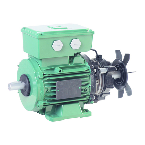
Do not operate the motor without the blower wheel attached. Without the blower wheel attached, the motor
will run continuously to a maximum speed and then stop.
Voltage symbols vary among different multimeters and may be displayed as Vac, AC, V, or a V beneath a
wavy line. Select the correct symbol and set the multimeter to the voltage closest to but higher than the
voltage you are measuring.
Read all instructions thoroughly and be familiar with the equipment before installing or working on it.
