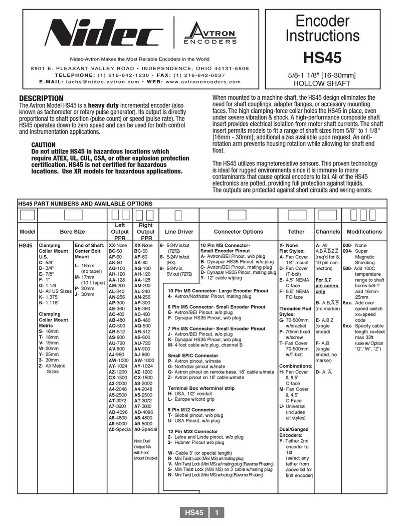
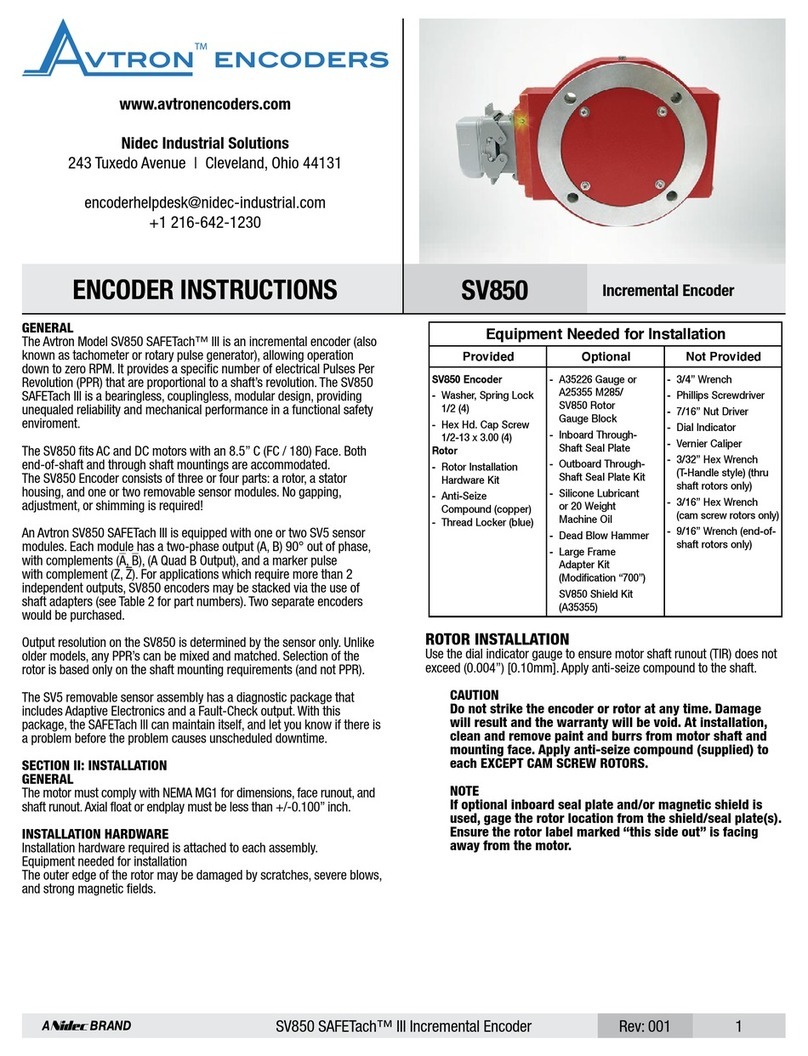
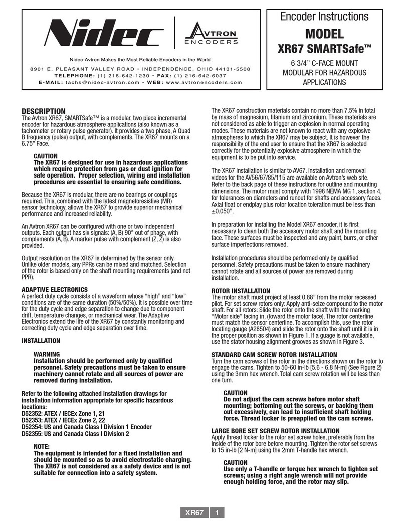
Nidec Avtron AV115 User manual

NOTE
THIN-LINE IIITM directly replaces THIN-LINE IITM and THIN-
LINETM models. THIN-LINE III models have Rev Code BA
or later. Special option 4xx selects an alternate PPR code
definition. Example: PPR Code 0, Special Option Code 401
= 1270 PPR (Left), No Right Output.
DESCRIPTION
The Avtron AV115 is a modular, two piece incremental encoder (also
known as a tachometer or rotary pulse generator). It provides a two
phase, A Quad B frequency (pulse) output, with complements. The
AV115 mounts on a 115mm C-Face, also known as a B-Flange.
Because the AV115 is modular, there are no bearings or
couplings required. This, combined with the latest magnetoresistive
(MR) sensor technology, allows the AV115 to provide superior
mechanical performance and increased reliability. An Avtron AV115 can
be configured with one or two independent outputs. Each output has
six signals: (A, B) 90° out of phase, with complements (A, B). A marker
pulse with complement (Z, Z) is also provided.
Output resolution on the AV115 is determined by the sensor only.
Unlike older models, any PPRs can be mixed and matched. Selection
of the rotor is based only on the shaft mounting requirements (and not
PPR).
8901 E. PLEASANT VALLEY ROAD
•
INDEPENDENCE, OHIO 44131-5508
TELEPHONE: (1) 216-642-1230
•
FAX: (1) 216-642-6037
E-MAIL:[email protected]
•
WEB: www.avtronencoders.com
Nidec-Avtron Makes the Most Reliable Encoders in the World
Encoder
Instructions
MODEL
AV115
AV115 PART NUMBERS AND AVAILABLE OPTIONS
Model Housing Type Shaft Size
(Thru Shaft Rotor) Cover Style Line Driver Single/Left
Output (PPR)
Right Output
(PPR) Connector Modifications
AV115 1- Single Output
2- Dual Output
C0- Non. Std. Shaft Size
XX- None
Thru Shaft Rotor
D2- 10mm DK- 38mm
DA- 11mm DL- 42mm
D3- 12mm DM- 45mm
DB- 14mm DN- 48mm
DC- 15mm DP- 52mm
DD- 16mm DR- 55mm
D4- 18mm DS- 60mm
DE- 19mm MU- 65mm*
DF- 24mm MV- 70mm*
DG- 28mm MW- 75mm*
DH- 30mm MY- 80mm*
DT- 32mm MZ- 85mm*
DJ- 36mm
E- Extended
Shaft Cover
F- Flat Cover
T- Flat Thru-
Hole Cover with
Shaft Seal (Seal
not available
on shafts larger
than 75mm)
D- Dome Cover
6- 5-24V in/out
8- 5-24 V in,
5-24 V out
high power
9- 5-24V in,
5V out
W-3 Ft. Cable, Sealed
See table below for other
options
000- No Modification
004- Add Housing Drain
(single output only)
005- Super Magnetic
Shielding
4xx- Special PPR
Enter Ø in the PPR
code(s), select the
special option code
below
9xx- Special Cable Length,
xx=length in feet
00W-
Connector on 18”
cable: Use w/ options
“T”,“U”
Equipment Needed for Installation
Provided Optional Not Provided
AV115 Stator/Housing
Socket Hd Cap Screw
M10 x 20mm (4)
AV115 Rotor
Socket Set Screw
M4 x 6mm (2) or Pre-
installed cam screw
Thread locker (blue)
Extended Shaft
Cover w/ Screws
6-32 x 0.31” (4)
Lock Washers
Thru Shaft Cover
w/ V-Ring Seal and
Silicone Lubricant
Phillips Screwdriver
2mm Hex Wrench
(T-Handle Style for Thru-
Shaft Rotors >70mm)
3mm Hex Wrench
8mm Hex Wrench
115mm FLANGE MOUNT
MODULAR
* Set Screw Rotor only
0- Non.
Std.
F- 60
G- 100
H- 120
A- 128
L- 240
N- 256
P- 300
E- 360
B- 480
Q- 500
R- 512
S- 600
V- 900
J- 960
Y- 1024
Z- 1200
3- 2000
4- 2048
5- 2500
D- 4096
8- 4800
9- 5000
0- Non-
Std.
F- 60
G- 100
H- 120
A- 128
L- 240
N- 256
P- 300
E- 360
B- 480
Q- 500
R- 512
S- 600
V- 900
J- 960
Y- 1024
Z- 1200
3- 2000
4- 2048
5- 2500
D- 4096
8- 4800
9- 5000
X- None
Connector Options
Mounted on Encoder Mounted on Flex Cable 00W
10 Pin MS 10 Pin
EPIC
10 Pin
mini MS
7 Pin
MS«
10 Pin
MS«
10 Pin
EPIC«
10 Pin
mini MS«
(*)8 Pin
M12
A-
w/o plug (std. phasing)
B-
w/o plug (Dynapar
HS35 phasing)
C- “A”
w/ plug
D- “B”
w/ plug
G-
w/ plug
Northstar
pinout
P-
w/ plug
R-
w/
plug
Not
Available
Not
Available
Z- 36”
Cable
w/
plug
S- 18”
Cable
w/
plug
T-
w/o plug
(Turck
Pinout)
U-
w/o plug
(US Pinout)
SPECIAL PPR OPTION CODES
OPTION
CODE
LEFT
PPR
RIGHT
PPR
401 1270 None
402 150 None
403 50 None
404 512 16
405 16 None
406 6000 None
407 2800 None
408 1400 None
409 30 None
410 None 6000
(*)Requires
Special
option 00W
AV115 1

INSTALLATIONS
Refer to the back page of these instructions for outline and mounting
dimensions. Axial float or endplay must be less than ±1.27mm.
In preparation for installing the Model AV115 Encoder, it is first
necessary to clean both the accessory motor shaft and the mounting
face. These surfaces must be inspected and any paint, burrs, or other
surface imperfections removed.
Installation procedures should be performed only by qualified
personnel. Safety precautions must be taken to ensure machinery
cannot rotate and all sources of power are removed during installation.
ELECTRICAL
A. Operating Power (Vin)
1. Volts........................5-24 VDC
2. Current ...................80mA, each output, no load
B. Output Format
1. 2O/ & Comp ...........A,A
–, B,B
–(differential line driver)
2. Marker ....................1/Rev, Z,Z
–
C. Signal Type .................Incremental, Square Wave, 50 ±10% Duty Cycle.
D. Direction Sensing .......O/ A leads O/ B for CW rotation as viewed from the
................................. back of the tach looking at the non-drive end of the motor.
E. Phase Sep. .................15% minimum
F. Frequency Range .......@5V, @1m cable, 250 kHz Max
................................. @24V, @300m cable, #8 output, 45 kHz Max
G. PPR.............................4-50000
H. Line Driver Specs.......See table
I. Connectors .................See connector options on page 1
J. Integral LED Indicator ..GREEN: power on, unit ok. RED: alarm on
................................. ORANGE: wiring fault
MECHANICAL
A. Rotor Inertia:...............12-25kg-cm2
B. Acceleration:...............5000 RPM/Sec. Max.
C. Speed:.........................5400 RPM Max.
D. Weight:........................0.9kg to 1.36kg.
E. Sensor to Rotor
Air Gap (nominal):.......0.58mm
Tolerance: ...................0.38mm
F. Rotor Axial Tolerance.±1.27mm
ENVIRONMENTAL
Solid cast aluminum stator and rotor
Fully potted electronics, protected against oil and water spray
Use “W” cable option on IP66/67 applications
V-Ring seals provided on through shaft covers
Operating Temperature:........... -40 to 100°C, 0-100% condensing humidity
Vibration: 18 g’s
Shock: 1 meter drop test
SPECIFICATIONS
ROTOR INSTALLATION
The motor shaft must project at least 16mm from the motor face. For
set screw rotors only: Apply anti-seize compound to the motor shaft.
For all rotors: Slide the rotor onto the shaft with the marking “This side
out” facing out (away from the motor face). The rotor centerline must
match the sensor centerline. To accomplish this, use the rotor locating
gauge (A28503) and slide the rotor onto the shaft until it is in the
proper position as shown in Figure 1. If a gauge is not available, use
the stator housing alignment grooves as show in Figure 3.
STANDARD CAM SCREW ROTOR INSTALLATION
Turn the cam screws of the rotor in the directions shown on the rotor
to engage the cams. Tighten to 5.6 - 6.8 N-m (See Figure2) using the
3mm hex wrench. Total cam screw rotation will be less than one turn.
CAUTION
Do not adjust the cam screws before motor shaft
mounting; bottoming out the screws, or backing them
out excessively, can lead to insufficient shaft holding
force. Thread locker is preapplied on the cam screws.
LARGE BORE SET SCREW ROTOR INSTALLATION
Apply thread locker to the rotor set screw holes, preferably from the
inside of the rotor bore before mounting. Tighten the rotor set screws
to 0.56 +/- 0.11 N*m (5 +/- in*lb). Large bore rotor set screw is M3
and should be tightened using a torque-measuring 1.5mm-drive hex
wrench
CAUTION
Use only a T-handle or torque hex wrench to tighten
set screws; using a right angle wrench will not provide
enough holding force, and the rotor may slip.
WARNING
Overtightening can lead to deformation &/or damage to
the rotor.
LINE DRIVER OPTIONS
Electrical Specifications 6 8 9 Units
Input Voltage 5-24 5-24 5-24 VDC
Nom Output Voltage 5-24 5-24 5 VDC
Line Driver 7272 Hx 7272
Output Resistance Typ
13 75 13 ohms
Maximum Peak Current 1500 3000 1500 mA
Maximum Average
Current 120 250 120 mA
Voh Typ VIN-1 VIN-1 VIN-1 VDC
Vol Typ 0.5 0.2 @ 10mA line
current 0.5 VDC
Cable Drive Capacity
1000’ @ 5V
500’ @ 12V
200’ @ 24V
1000’ 1000’ feet
Protection
Reverse
Voltage yes yes yes
Short
Circuit yes yes yes
Transient yes yes yes
Power to A,
Gnd to A/ yes yes yes
Alarm
+V(out) Output voltage equal to input voltage.
Alarm* Open collector, normally off, goes low on alarm,
sink 100mA max, 50VDC max
LED Green=power on, Red=Alarm, Orange=Wiring Error
Marker One per revolution. Pulse width
approximately 2°
*Alarm not available on connector option “G” (NorthstarTM compatible pinout)
** Electrical specifications for THIN-LINE III model (rev BA or later), consult Avtron
for earlier model specifications.
5.6-6.8 N-M
TIGHTEN: 50-60 IN-LB
TO LOCK ROTOR
ROTATE CAM SCREWS
OF NOTCHES
IN HOUSING
ALIGN ROTOR FACE
WITH BOTTOM
ALIGNMENT NOTCH
Jack Screw Holes
M6
CW CW
FIGURE 2
U.S. Patent
7,485, 997
LINE DRIVER OPTIONS
AV115 2

STATOR HOUSING INSTALLATION
The stator housing is attached to the motor using four socket head
cap screws M10 x 0.5 x 20mm long, locating on a 150mm bolt circle.
Longer bolts (not included), are required for sandwich installation
between a motor and a brake. Install the four mounting bolts using
thread locker and torque to approximately 27 to 40 N-m using the
8mm T-handle hex wrench.
VERIFY ROTOR LOCATION
To ensure the rotor is properly located on the shaft: remove the back
cover if factory-preinstalled, and verify that the outer face of the rotor is
at the same depth as the alignment grooves, using a straight edge tool.
(Figure 3)
CAUTION
Do not use silicone sealants or caulk of any kind on the
motor or encoder face; these can cause misalignment
or sensor scraping damage. The AV115 electronics are
fully sealed; water may enter and leave the rotor area
as needed. A drain hole option is available if frequent
moisture buildup is expected.
COVER INSTALLATION
Covers must not interfere with the motor shaft or rotor. The longest
shaft that can be used without interfering is 17.5mm with a standard
flat cover (Cover Style option “F”) and 63.5mm with an extended “pie
pan” cover (Cover Style option “E”). Through shaft covers with seals are
available for other applications (Cover Style option “T”).
EXTENDED COVER MOUNT
(Cover Style option “E”)
The extended cover mounts to the encoder housing using quantity 4
#6-32 x 0.31" screws, lock washers, and thread locker.
THRU SHAFT AND FLAT COVER INSTALLATION
(Cover Style option “T” and “F”)
The housing has a machined step in the outboard face to accept the
cover and a recessed groove for the retaining ring. Insert the cover,
line up ears on cover, smooth side facing out, fully into the machined
step until it seats against shoulder. Using a spiral assembly method,
install the retaining ring by first inserting the squared off end into the
machined groove. Flex the ring and insert it into the groove walking
it around the perimeter (A flat blade screwdriver can be used). Final
position should have the ring fully seated into groove. Remove the
cover by reversing above procedure, starting with the tang end.
V-RING INSTALLATION FOR THRU SHAFT COVERS
(Cover Style option “T”)
For thru shaft covers, verify that the shaft passes completely through
the hole in the cover. Apply a small amount of silicone lubricant to
the cover plate around the thru shaft hole. The V-Ring seal should
compress axially when it is pressed against the clean, smooth face
of the cover plate. See Figure 4 for proper installation and V-Ring
compression.
WIRING
CAUTION
Be sure to remove power before wiring the encoder. Be
sure to ground the cable shield: It can be connected to
case ground at the encoder, or grounded as the receiving
device, but should not be grounded on both ends. See
note below for Danaher/Northstar wiring.
Refer to the wiring diagrams for specific information on each option.
The AV115 can be wired for single phase or two phase, either with
or without complements, with or without markers. For bidirectional
operation, Phase A channel leads phase B channel for clockwise shaft
rotation as viewed from the anti-drive or accessory end of the motor
(AV115 mounting end).
NOTE
Wiring option “G” provides a pinout compatible with
NorthstarTM encoders, with a cable shield connection on
pin 10. Note that this option does not ground the shield;
Avtron still recommends grounding the shield at the
drive end of the cable for all wiring options.
CORRECTIVE ACTION FOR PHASE REVERSAL
1) Remove Power.
2) Exchange wires on cable, either at encoder cable end,
or at speed controller end (but not both).
a) Single Ended 2 Phase Wiring (see wiring diagram)
Exchange A and B at the use end of the wires.
b) Differential 2 Phase Wiring (see wiring diagram)
Exchange either A with A– in the phase A pair OR
B with B– in the phase B pair but NOT both.
3) Apply Power.
4) Verify encoder feedback is correct, using hand rotation
of shaft, or jog mode of the speed controller.
Interconnecting cables specified in the wire selection chart are based
on typical applications. Physical properties of cable such as abrasion,
temperature, tensile strength, solvents, etc., are dictated by the specific
application. General electrical requirements are: stranded copper,
22 through 16 AWG (Industrial EPIC connector type options can use
14 AWG), each wire pair individually shielded with braid or foil with
drain wire, .05 uf of maximum total mutual or direct capacitance,
outer sheath insulator. See specifications for maximum cable length.
Stranded 22 AWG wire should not be used for cable runs greater then
61 meters. If 22 AWG is used with EPIC type connector options the wire
ends should be tinned.
FAULT-CHECK
After power-up and the rotor position is checked by the sensor, the
Fault-Check LED will turn GREEN.
If the adaptive electronics reach their adjustment limit for any reason,
the Fault-Check alarm and LED will notify the drive and operator of an
impending failure. The LED will turn RED if the Adaptive Electronics
reach their adjustment limit. This output occurs before an actual
failure, allowing steps to be taken to replace the unit before it causes
unscheduled downtime. Fault-Check annunciation is available as an
“alarm” output through the connector and as an integral LED.
If there is a wiring error, such as an output being shorted to ground
or +V or another output, the Fault-Check LED will turn ORANGE. The
ORANGE LED may blink intermittently, depending on voltage and
severity of short.
TROUBLESHOOTING
If the drive indicates a loss of encoder/tach fault and the AV115 fault-
check LED is not illuminated, check the encoder power supply. If power
is present, check polarity; one indicator of reversed power supply is
that all outputs will be high at the same time. If the drive indicates
encoder fault, but the LED shows GREEN, then check the wiring
between the drive and the encoder. If the wiring appears correct and
in good shape, test the wiring by replacing the AV115. If the new unit
shows GREEN, and the drive still shows encoder loss/tach fault, then
the wiring is faulty and should be repaired or replaced.
If the alarm output and/or LED indicate a fault (RED):
1. Remove the rear cover, and use the built-in gauge to check the
location of the rotor (see Figure 1). Ensure the label marked “This side
out” is facing away from the motor.
2. Remove the AV115 from the motor. Clean the housing mounting
surface for the AV115 housing. Ensure the AV115 is directly mounted
on the motor, with no sealant, gasketing, or other materials, and is
firmly bolted in place.
If the alarm output and/or LED indicate a fault (RED)
On a properly mounted AV115 and the rotor is properly located, replace
the AV115 sensor.
AV115 3
CONNECTOR SPARE PARTS
STYLE OPTION
CODE
ENCODER
SIDE CABLE SIDE PLUG
Industrial
EPIC on
Encoder
Industrial
EPIC w/
Adapter
Block
P,G
Q
315233 Base 315937 Hood
Conn1-02315229 Terminal 315936 Terminal
401112 Adapter
Industrial
EPIC on 3'
Cable
Z
315232 Surface 315937 Hood
Conn1-02
315229 Terminal 315936 Terminal
471819 Bushing 401112 Adapter
Mini-MS
Twist Lock R, S 315296 Base 316110 Plug
An oscilloscope can also be used to verify proper output of the encoder
at the encoder connector itself and at the drive/controller cabinet.
If the outputs show large variations in the signals at steady speed
(jitter or “accordion effect”, see figure 5), check rotor position. If the
rotor position is correct, the motor or shaft may be highly magnetized.
Replace any magnetized material nearby with non-magnetic material
(aluminum, stainless) (especially shafts). For GE CD frame motors and
similar styles, Avtron offers non-magnetic stub shafts. If variations
persist, consider replacing the encoder with super-shielded models,
option -005, or use retrofit shielding kits AVSKxxx yy z, where
xxx=model (ex: 56A), yy=rotor (ex: CB), and z=cover (ex: F).
If the alarm output and/or LED indicate a wiring fault (ORANGE):
Remove all output wires/connections (A,A/,B,B/,Z,Z/). The LED should
turn GREEN. If the LED does not turn GREEN, the encoder is not
receiving enough voltage at +V to properly operate. Correct input
voltage problem at power supply or cabling.
If the LED turns GREEN once all outputs are disconnected, reconnect
each output, one at a time, monitoring for ORANGE LED. For partial/
resistive short circuits, the LED may take a few minutes to turn
ORANGE. To speed the troubleshooting process, if possible, spin the
encoder while replacing individual output connections. This will make
the ORANGE LED condition occur faster. Once the shorted output(s)
are located, correct the shorting condition, and the encoder LED should
remain GREEN.
If the LED is OFF, but power is being applied to the encoder, check
the output voltage level at A, A/,B, B/. If all outputs are ON (≈+V), the
connections to +V and COM are reversed. Swap connections between
+V and COM; the LED should turn GREEN.
NOTE:
Do not use rotors from THIN-LINE I (M56, M56S, M67,
M85, M115) with THIN-LINE III. This will cause incorrect
PPR output, but the Encoder LED will remain green.
ENCODER REMOVAL
The AV115 stator housing can be removed by loosening and removing
the socket head cap screws.
CAM SCREW ROTOR REMOVAL
Disengage the (2) cam screws by turning them counterclockwise less
than 1 full turn. The cam heads will visibly move away from the shaft.
Remove the rotor by hand by pulling it away from the motor. If the rotor
will not move, do NOT use a gear puller, and do not use a heat gun.
Instead, insert two M6 screws, >25mm length into the Jack Screw
Holes shown in Fig 2. Alternately tighten the screws to push the rotor
away from the motor and remove it.
LARGE BORE SET SCREW ROTOR REMOVAL
Disengage the (2) set screws by turning them counterclockwise until
removed from the rotor. Retain the set screws. Remove the rotor by
hand by pulling it away from the motor. If the rotor will not move, do
NOT use a gear puller, and do not use a heat gun. Instead, pry the
rotor away from the motor gently, being careful to only pry against the
rotor metal hub and not the magnetic outer strip.
FIGURE 5
VARIATION > ± 15%
PHASE A
PHASE B
AV115 4

ALIGNMENT NOTCH
ALIGN ROTOR FACE
WITH BOTTOM
OF NOTCHES
IN HOUSING
ALIGNMENT
GROOVES
STRAIGHT
EDGE TOOL
MOTOR
ENCODER
FIGURE 3
V-RING SEAL
COVER PLATE
APPLY GREASE TO
COVER WHERE SEAL
CONTACTS
SHAFT
ENCODER
“A”
ACCESSORY
MOUNTING FACE
5.33 MIN
6.86 MIN
7.87 MIN
9.65 MIN
“A”
ADD’L SHAFT
LENGTH REQ’D
FOR V-RING
4.57 ±0.51
6.10 ±0.76
7.11 ±1.02
8.89 ±1.27
70.002 - 76.200
38.100 - 66.675
22.225 - 34.925
12.700 - 15.875
V-RING WIDTH
INSTALLED
SHAFT DIAMETER
COVER PLATE
RETAINING RING
V-RING WIDTH
SEE CHART
FIGURE 4
(4) M10 x 1.5 x 15.00 FULL THREAD
ø.127 M A
ø150.00
0.75 MAX x 45° CHF
-B-
-A-
.05
ø.102 B
A
(4) M10 x 1.5 x 20.00 LG
TIGHTENING TORQUE - 50 NM
(2) M4 x 0.7 x 6.0 LG
SET SCREW
TIGHTENING
TORQUE - 2 NM
ROTOR SETTING TOOL
SUPPLIED WITH AV115
COVER
RETAINER
45°115.000
114.898
DIA
16.00
17.70
SEE SPARE PARTS
CHART FOR AVAILABLE
SHAFT SIZES
4.1 MAX
16.71 ±1.27
[0.658 ±0.050]
11.30 +/-0.25
[0.445 +/-0.010]
6.73 ±0.13
[0.265 ±0.005]
SEE SPARE PARTS
CHART FOR ROTOR ID
97.18 +/-0.08
[3.826 +/-0.003]
ROTOR OD
FIGURE 1
AV115 5

Extended and Flat Cover Plates
Shaft Size Model Extended Shaft Cover Kit Flat Cover Kit Dome Cover
Any AV56A, AV67, AV115 A35841 A37298 B29992-3
Any AV56S A36526 A37298 N/A
Any AV85 A35841 A36525 N/A
THIN-LINE II & III Spare Parts (AV56/AV67/AV85/AV115 Only)
SAE/USA Sizes
Shaft
Size
Rotors AV56A, AV67,
AV85, AV115 Thru-Shaft Covers
Option
Code
Cam
Screw Set Screw
AV56, AV67 &
AV115 Cover
Kit
AV85
Cover /kit Seal Only
.500/.4995 CA AVTR1-CA N/A A36521-TA A36523-TA 471960
.625/.6245 CB AVTR1-CB N/A A36521-TB A36523-TB 471877
.875/.8745 CC AVTR1-CC N/A A36521-TC A36523-TC 471963
.9375/.9370 CD AVTR1-CD N/A A36521-TD A36523-TD 471963
1.000/.9995 CE AVTR1-CE N/A A36521-TE A36523-TE 471964
1.125/1.1245 CF AVTR1-CF N/A A36521-TF A36523-TF 471965
1.250/1.2495 CG AVTR1-CG N/A A36521-TG A36523-TG 471967
1.375/1.3745 CH AVTR1-CH N/A A36521-TH A36523-TH 471952
1.500/1.4995 CT AVTR1-CT N/A A36521-TT A36523-TT 471969
1.625/1.6245 CJ AVTR1-CJ N/A A36521-TJ A36523-TJ 471969
1.750/1.7495 CK AVTR1-CK N/A A36521-TK A36523-TK 471970
1.875/1.8745 CL AVTR1-CL N/A A36521-TL A36523-TL 471970
2.000/1.9995 CM AVTR1-CM N/A A36521-TM A36523-TM 471971
2.125/2.1245 CN AVTR1-CN N/A A36521-TN A36523-TN 471972
2.250/2.2495 CQ AVTR1-CQ N/A A36521-TQ A36523-TQ 471972
2.375/2.3745 CP AVTR1-CP N/A A36521-TP A36523-TP 471953
2.500/2.4995 CR AVTR1-CR N/A A36521-TR A36523-TR 471954
2.625/2.6245 TS N/A AVTR1-TS A36521-TS A36523-TS 471954
2.750/2.7495 TW N/A AVTR1-TW A36737-TW A36523-TW 471955
2.875/2.8745 TU N/A AVTR1-TU A36521-TU A36523-TU 471956
3.000/2.9995 TV N/A AVTR1-TV A36521-TV A36523-TV 471956
3.1250/3.1245 T4 N/A AVTR2-T4 A36737-T4 A36523-T4 471957
3.1875/3.1870 T7 N/A AVTR2-T7 A36737-T7 A36523-T7 471957
3.250/3.2495 TZ N/A AVTR2-TZ A36737-TZ A36523-TZ 471957
AV115 6

THIN-LINE II & III Spare Parts (AV56/AV67/AV85/AV115 Only)
Metric Sizes
Shaft
Size
Rotors AV56A, AV67,
AV85, AV115 Thru-Shaft Covers
Option
Code
Cam
Screw Set Screw
AV56, AV67 &
AV115 Cover
Kit
AV85
Cover /kit Seal Only
10mm D2 AVTR1-D2 N/A A36522-M2 A36524-M2 471959
11mm DA AVTR1-DA N/A A36522-MA A36524-MA 471959
12mm D3 AVTR1-D3 N/A A36522-M3 A36524-M3 471960
14mm DB AVTR1-DB N/A A36522-MB A36524-MB 471961
15mm DC AVTR1-DC N/A A36522-MC A36524-MC 471961
16mm DD AVTR1-DD N/A A36522-MD A36524-MD 471877
18mm D4 AVTR1-D4 N/A A36522-M4 A36524-M4 471962
19mm DE AVTR1-DE N/A A36522-ME A36524-ME 471951
24mm DF AVTR1-DF N/A A36522-MF A36524-MF 471964
28mm DG AVTR1-DG N/A A36522-MG A36524-MG 471965
30mm DH AVTR1-DH N/A A36522-MH A36524-MH 471966
32mm DT AVTR1-DT N/A A36522-MT A36524-MT 471967
36mm DJ AVTR1-DJ N/A A36522-MJ A36524-MJ 471968
38mm DK AVTR1-DK N/A A36522-MK A36524-MK 471969
42mm DL AVTR1-DL N/A A36522-ML A36524-ML 471969
45mm DM AVTR1-DM N/A A36522-MM A36524-MM 471970
48mm DN AVTR1-DN N/A A36522-MN A36524-MN 471971
52mm DP AVTR1-DP N/A A36522-MP A36524-MP 471971
55mm DR AVTR1-DR N/A A36522-MR A36524-MR 471972
60mm DS AVTR1-DS N/A A36522-MS A36524-MS 471953
65mm MU N/A AVTR1-MU A36522-MU A36524-MU 471954
70mm MV N/A AVTR1-MV A36522-MV A36524-MV 471955
75mm MW N/A AVTR1-MW A36522-MW A36524-MW 471956
80mm MY N/A AVTR1-MY A36737-MY A36524-MY 471957
85mm MZ N/A AVTR2-MZ A36737-MZ A36524-MZ 471958
AV115 7

OPTION
“L” & “W”
OPTION
“P” & “Z”
SIGNAL CODING TABLE
BLACK
RED
GREEN
YELLOW
BLUE
GRAY
ORANGE
WHITE
BROWN
VIOLET
1
6
2
7
3
8
4
9
5
10
A
B
D
G
E
H
C
I
F
J
1
6
2
7
3
8
4
9
NC
NC
FOR DIFFERENTIAL APPLICATIONS
REF
SIGNAL
COM
+V
ØA
ØA
–
ØB
ØB
–
Z
Z
–
+V out (alarm)
ALM
+5 TO +24 VOLTS
= MARKER
(SEE LINE
DRIVER
OPTIONS)
SIGNAL CODING TABLE
RED
GREEN
BLACK
BROWN
VIOLET
6
2
1
5
10
D
F
NC
NC
D
F
NC
NC
B
D
A
5
10
6
2
1
NC
NC
OPTION
“P” & “Z”
SIGNAL CODING TABLE
RED
GREEN
BLUE
BLACK
BROWN
VIOLET
6
2
3
1
5
10
D
A
B
F
NC
NC
D
A
B
F
NC
NC
B
D
E
A
F
J
6
2
3
1
NC
NC
FOR SINGLE ENDED TWO PHASE APPLICATIONS
FOR SINGLE ENDED SINGLE PHASE APPLICATIONS
REF
SIGNAL
+V
ØA
ØB
COM
+V (out)
ALM
REF
SIGNAL
+V
SIG
COM
+V (out)
ALM
OPTION
“G” & “Q”
OPTION
“Y”
OPTION
“L” & “W”
OPTION
“G” & “Q”
OPTION
“Y”
OPTION
“P” & “Z”
OPTION
“L” & “W”
OPTION
“G” & “Q”
OPTION
“Y”
OPTION
“R” & “S”
F
D
A
H
B
J
C
K
NC
NC
OPTION
“R” & “S”
OPTION
“R” & “S”
OPTION
“A”,“B”,“C”,“D”
OPTION
“A”,“B”,“C”,“D”
OPTION
“A”,“B”,“C”,“D”
F
D
A
H
B
I
C
J
NC
NC
OPTION
“L” & “W”
SIGNAL CODING TABLE
BLACK
RED
GREEN
YELLOW
BLUE
GRAY
ORANGE
WHITE
BROWN
VIOLET
7
2
1
3
4
5
6
8
NC
NC
1
2
3
4
5
6
7
8
NC
NC
FOR DIFFERENTIAL APPLICATIONS
REF
SIGNAL
COM
+V
ØA
ØA
–
ØB
ØB
–
Z
Z
–
+V out (alarm)
ALM
+5 TO +24 VOLTS
= MARKER
(SEE LINE
DRIVER
OPTIONS)
OPTION
“T”
OPTION
“U”
WIRING DIAGRAMS
BELDEN
2 PAIR
3 PAIR
4 PAIR
3 CONDUCTOR
TYPICAL WIRE SELECTION CHART
for 18 AWG, multiple pair, individually shielded
9368
9773 or 9369
9388
9365
5620B1802
6445
6444
5640B1801
ALPHA
For option “W”, unused outputs must be insulated to prevent
accidental contact.
NOTE: Avtron standard 3 year warranty applies. Copies avail-
able upon request. Specifications subject to change without
notice.
AV115 8

BLACK
RED
GREEN
YELLOW
BLUE
GRAY
ORANGE
WHITE
BROWN
VIOLET
OUTPUT OPTIONS
9
4
5
10
2
8
3
7
6
1
Vcc
OUT
COM
300 OHM
MIN.
GND
FUNCTION
ENCODER
ØB
ØA
ØA
ØB
4-16 VDC SOLID STAT E RELAY
Q5
MMFT6661
LINE
DRIVER
NOTE 1
CR8
{
FUNCTIONAL DIAGRAM
50 mA MAXIMUM
“W” “P” & “Q”
MARKER
MARKER COMPLEMENT
COMMON
+V (Encoder Power)
{
BLACK
RED
GREEN
YELLOW
BLUE
GRAY
ORANGE
WHITE
BROWN
VIOLET
OUTPUT OPTIONS
9
4
5
10
2
8
3
7
6
1
MARKER
MARKER COMPLEMENT
GND
FUNCTION
+V (Encoder Power)
COMMON
24
VDC
RELAY
+
-
POWER
SUPPLY 115 VAC
SINK 100 mA MAXIMUM,
WITHSTAND 50 V MAXIMUM
REFERENCED TO COMMON
Q5
MMFT6661
ENCODER
FUNCTIONAL DIAGRAM
ØB
ØA
ØA
ØB
LINE
DRIVER
NOTE 1
CR8
“W” “P” & “Q”
Applies to all model AV115 encoders, except for wiring option “A”, “B”, “C”, “D”, “G”, “Q”, “R”, “S”, “T” and “U”.
ALARM OUTPUT CONNECTION
Avtron THIN-LINE II & III encoders provide an alarm signal if maintenance is required under specific circumstances. An
optional internal alarm LED indicator is also available. Green indicates power on, red or orange indicates alarm on. Following
are application examples provided to help install the alarm output.
Example 1. Alarm output using +V(OUT). +V(OUT) is equal to +V, the encoder power supply.
THIN-LINE II™ & III™
Application Examples
Example 2. Alarm Output Using Separate 24 VDC Power Supply and Relay.
AV115 9

140.4
OPTIONAL ISOLATED DUAL OUTPUT
115.025
115.076
DIA
(21.3)
4.6
3.0
69.9
123.8
67.5
1/2-14
NPT
50.0
80.4
45°
10.75 DIA 4 HOLES
EQUALLY SPACED
ON A 150.00 DIA
48.0
63.541.3
1.0 M MIN
1/2-14 NPT
4.1
105.0
40.0
OPTION "W"
SEALED FLEXIBLE CABLE
ADDITIONAL OPTIONS
SHOWN BELOW
OPTION "Z"
SURFACE MOUNTED PLUG-IN
INDUSTRIAL CONNECTOR
4.50 DIA
4 HOLES
50.0
35.3 MAX
17.13
1.0 M MIN
CABLE LENGTH
69.9
63.5
#22 AWG [0.35 MM2] LEADS
7x.051 MM2STRANDING
BARE ENDS ARE STRIPPED
9.5 AND TINNED
115.000
114.898
DIA
21.3
132.5
152.3
82.0
69.4
OPTIONAL COVER
FOR EXTENDED
SHAFT MOTORS
SEE NOTE 4
LED ALARM
INDICATOR
150.9 MAX
DUAL OUTPUT UNITS ONLY
OPTIONS "P" & "G"
PLUG-IN INDUSTRIAL
CONNECTOR
11.20 +/-0.25
CAM SCREWS
22.4
THRU, 180° APART
ON A 63.5 DIA.
FOR AVAILABLE
BORE SIZES,
SEE PAGE 1 P/N TABLE.
45°
±10°
90°
±10°
ROTOR
72.9
OPTION “R”
MINI MS WITH PLUG
OPTION “S”
MINI MS WITH PLUG
4 – STANDARD FLAT COVER SHOWN IN FRONT VIEW.
OPTIONAL THRU-SHAFT COVER NOT SHOWN
3 – DIMENSIONS IN MILLIMETERS
2 – ALL DIMENSIONS ARE APPROXIMATE
1 – WEIGHT: 0.9 TO 1.36 KG.
NOTES:
REV: 09-23-19
Features and specifications subject to change without notice.
Avtron standard warranty applies. All dimensions are in millimeters approx.
THINE-LINETM, THIN-LINE IITM and THIN-LINE IIITM are trademarks of Nidec-Avtron.
All Rights Reserved.
OUTLINE DRAWING
8901 E. PLEASANT VALLEY ROAD
•
INDEPENDENCE, OHIO 44131-5508
TELEPHONE: (1) 216-642-1230
•
FAX: (1) 216-642-6037
E-MAIL:[email protected]
•
WEB: www.avtronencoders.com
Nidec-Avtron Makes the Most Reliable Encoders in the World
Maximum Shaft
Length
Cover Length
F 17.5
D 24.3
E 63.5
T Unlimited
AV115 10
Table of contents
Other Nidec Media Converter manuals

Nidec
Nidec SI-Encoder V2 User manual

Nidec
Nidec Avtron AV44 User manual

Nidec
Nidec Avtron Encoders HS44 User guide

Nidec
Nidec Unidrive M200 User manual

Nidec
Nidec Avtron SAFETach III SV850 User manual

Nidec
Nidec Avtron SMARTSafe XR67 User manual

Nidec
Nidec Avtron AV45 Series User manual

Nidec
Nidec Avtron AV6A User manual

Nidec
Nidec Avtron HS45 Series User manual