SV850 SAFETach™ III Incremental Encoder 4Rev: 001
General electrical requirements are: stranded copper, 22 thru 16 gauge
(Industrial EPIC Connector options can use 14-20 AWG), each wire pair
individually shielded with braid or foil with drain wire, 0.05 uF maximum
total mutual or direct capacitance, outer sheath insulator, 1,000 ft. max.
See WIRE SELECTION CHART in Figure 6 for some suggested cables.
See Figure 7 for examples of alarm output wiring.
NOTE
When using the industrial connector (“G”, “P” options),
the minimum wire size is 20 gage, and 20 gage (only) wire
ends must be tinned with solder before connection at the
screw terminals.
MAINTENANCE
GENERAL
This section describes routine maintenance for the Avtron SV850 Encoder.
For support, contact field service for Avtron Encoders at
216-642-1230. For emergency after hours service contact us at
216-641-8317. The SV850 SAFETach III circuitry includes a diagnostic
package that includes Adaptive Electronics and a Fault-Check output.
ADAPTIVE ELECTRONICS
A perfect duty cycle consists of a waveform whose “high” and “low”
conditions are of the same duration (50%/50%). The SV850 adaptive
electronics extends the life of the SV850 by constantly monitoring and
correcting duty cycle over time.
FAULT-CHECK
After power-up and the rotor position is checked by the sensor, the Fault-
Check LED will turn GREEN.
If the adaptive electronics reach their adjustment limit for any reason,
the Fault-Check alarm and LED will notify the drive and operator of an
impending failure. The LED will turn RED if the Adaptive Electronics reach
their adjustment limit. This output occurs before an actual failure, allowing
steps to be taken to replace the unit before it causes unscheduled
downtime. Fault-Check annunciation is available as an “alarm” output
through the connector and as an integral LED.
TROUBLESHOOTING:
If the drive indicates a loss of encoder/tach fault and the SV850 fault-
check LED is not illuminated, check the encoder power supply. If power
is present, check polarity; one indicator of reversed power supply is that
all outputs will be high at the same time. If the drive indicates encoder
fault, but the LED shows GREEN, then check the wiring between the drive
and the encoder. If the wiring appears correct and in good shape, test
the wiring by replacing the SV5 sensor module. If the new module shows
GREEN, and the drive still shows encoder loss/tach fault, then the wiring is
faulty and should be repaired or replaced.
WARNING
Only use SV5 sensors in SV850 Encoders. Use of other
sensors will not retain the functional safety compliance of
the SV850.
If the alarm output and/or LED indicate a fault (RED):
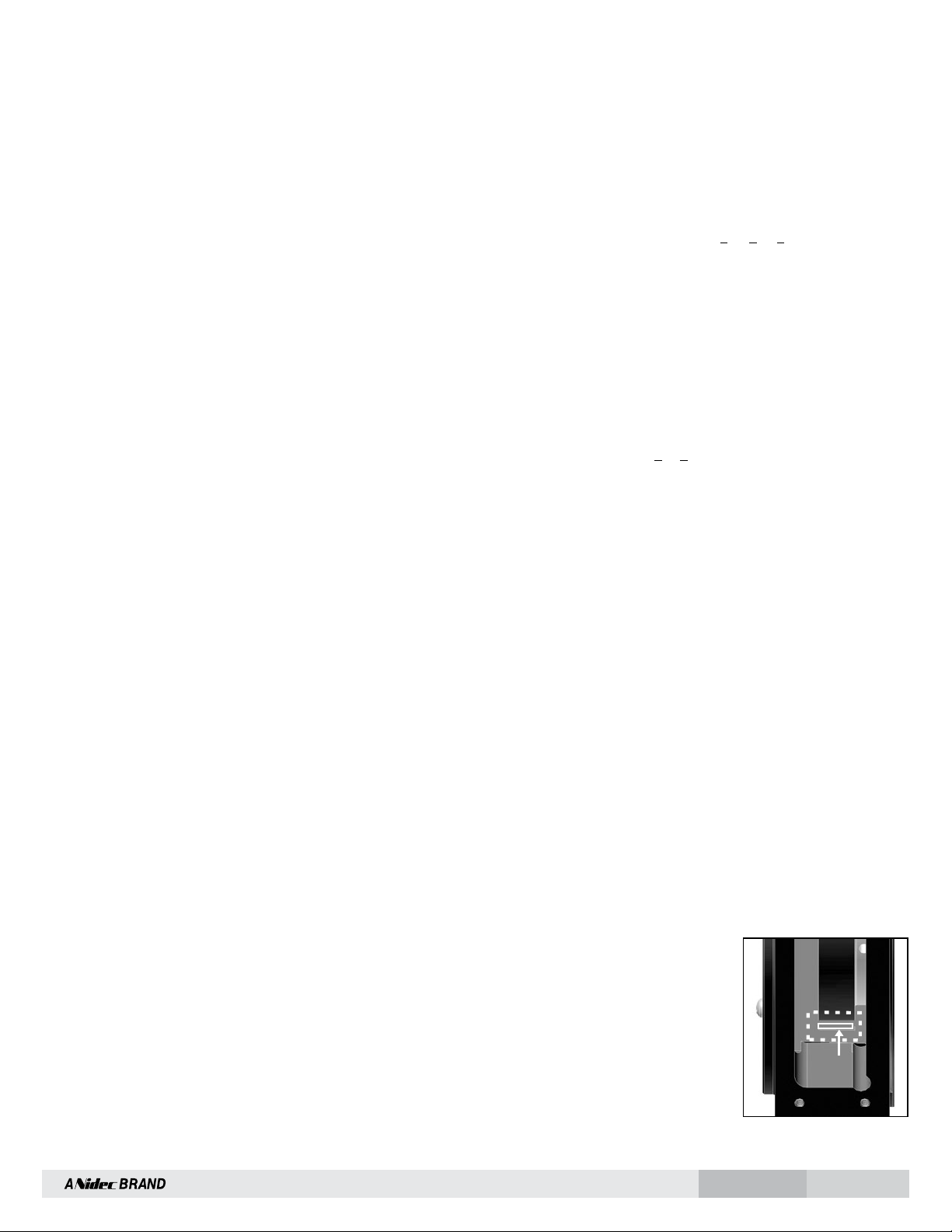
1. Remove a sensor plate or one of the sensors, and use
the built-in gauge to check the location of the rotor (see Figure
2.1). Ensure the label marked “This side out” is facing away
from the motor.
2. Remove the SV5 sensor from the housing. Clean the housing
mounting surface for the SV5 sensor and the SV850 housing.
Ensure the SV5 sensor is directly mounted on the SV850
housing, with no sealant, gasketing, or other materials, and
that it is firmly bolted in place.
If the alarm output and/or LED indicate a fault (RED) on a properly
mounted SV5 sensor and the rotor is properly located, replace the SV5
sensor.
An oscilloscope can also be used to verify proper output of the SV850
encoder at the encoder connector itself and at the drive/controller cabinet.
If the outputs show large variations in the signals at steady speed (jitter
or “accordion effect”, see figure 9), check rotor position. If the rotor
position is correct, the motor or shaft may be highly magnetized. Replace
any magnetized material nearby with non-magnetic material (aluminum,
stainless) (shafts, etc). For GE CD frame motors and similar styles, Avtron
offers non-magnetic stub shafts (included with all “U” style rotor kits).
If variations persist, consider replacing the sensors with super-shielded
models, option -004.
If the alarm output and/or LED indicate a wiring fault (ORANGE):
Remove all output wires/connections (A, A, B, B, Z, Z). The LED should
turn GREEN. If the LED does not turn GREEN, the encoder is not receiving
enough voltage at +V to properly operate. Correct input voltage problem at
power supply or cabling.
If the LED turns GREEN once all outputs are disconnected, reconnect each
output, one at a time, monitoring for ORANGE LED. For partial/resistive
short circuits, the LED may take a few minutes to turn ORANGE. To speed
the troubleshooting process, if possible, spin the encoder while replacing
individual output connections. This may make the ORANGE LED condition
occur faster. Once the shorted output(s) are located, correct the shorting
condition, and the encoder LED should remain GREEN.
If the LED is OFF, but power is being applied to the encoder, check
the output voltage level at A, A,B, B. If all outputs are ON (≈+V), the
connections to +V and COM are reversed. Swap connections between +V
and COM; the LED should turn GREEN.
STATOR HOUSING REMOVAL
To remove the stator housing remove the qty 4 1/2 13 x 3” bolts holding
the housing to the motor.
CAUTION
Take care that the housing does not fall from the pilot and
cause the sensors to crash into the rotor. Damage to the
sensor or rotor could result.
ROTOR REMOVAL
Remove shaft rust and burrs before removing the rotor.
THROUGH-SHAFT AND UNIVERSAL (KA-K9):
Loosen the set or cam screws holding the rotor to the shaft. The cam
screws rotate less than one turn to disengage the shaft. The stub shaft
adapter from the universal (Ux) rotors can be left in place.
NOTE
Do not remove the cam screws from the rotor.
Remove the rotor by hand, taking care not to damage the outer
magnetized ring.
If the rotor cannot be removed by hand, use a gear puller taking care not
to damage the outer magnetized ring.
DO NOT APPLY HEAT TO THE ROTOR. ROTOR ALIGNMENT GROOVE
Figure 2.1
Rotor magnetic strip aligns with groove.