Nidec Avtron AV44 User manual

AV44 Solid Shaft Incremental Encoder
AV44
1
www.avtronencoders.com
Nidec Industrial Solutions
243 Tuxedo Avenue | Cleveland, Ohio 44131
+1 216-642-1230
Solid Shaft Magnetic
Incremental Encoder
ENCODER INSTRUCTIONS
Rev: 003
DESCRIPTION
The Avtron™ Encoders model AV44 Solid Shaft Incremental Encoder
is a speed and position incremental transducer (also known as a
tachometer or pulse generator). When mounted to a motor or machine,
its output is directly proportional to relative shaft position (pulse count)
or speed (pulse rate). The AV44 employs magnetic sensing technology
and operates down to zero speed, and it can be used for both control
and instrumentation applications. The AV44 encoder offers 2-phase
outputs (A, B) 90° apart for direction sensing, with complements (/A, /B)
and with marker pulse and complement (Z, /Z).
CAUTION
AV44 is not certified for hazardous locations. Do not utilize
AV44 in hazardous locations which require ATEX, UL, CUL,
CSA, or other explosion protection certification. Use Avtron
Encoders XR or XP models for hazardous applications.
The AV44’s housing is rugged cast aluminum with a durable powder
coat finish, and the electronics are fully encapsulated to protect against
the elements. The AV44 is a flange-mounted encoder available with
industry standard “B10 Euro-flange” or “PY” flange/shaft configurations
or on a foot-mount bracket for coupling for use in a wide range of
industrial applications. AV44 is not recommended for pulley or chain
drive applications.
The AV44 has a diagnostic package that includes Adaptive Electronics
and red/orange/green LED for local status indication. A Fault-Check
output is also available. With this package the AV44 can maintain itself
and provide an alarm if there is a problem before the problem causes
unscheduled downtime.
ADAPTIVE ELECTRONICS
A perfect duty cycle consists of a waveform whose “high” and “low”
conditions are of the same duration (50%/50%). It is possible over time
for the duty cycle and edge separation to change due to component
drift, temperature changes, or mechanical wear. The Adaptive
Electronics extend the life of the AV44 by constantly monitoring and
correcting duty cycle and edge separation over time.
FAULT-CHECK
If the Adaptive Electronics reach their adjustment limit, the LED will turn
red. If selected the Fault-Check alarm will notify the drive and operator
of an impending failure. This output can occur before a failure, allowing
steps to be taken to replace the unit before it causes unscheduled
downtime. Fault-Check annunciation is available as an “alarm” output
option (Mod Code 068).
CAUTION
The AV44 is not considered as a safety device and is not
suitable for connection into a safety system.
WARNING:
Installation should be performed only by qualified personnel.
Safety precautions must be taken to ensure machinery
cannot rotate and all sources of power are removed during
installation.
INSTALLATION
Refer to the back pages of these instructions for outline and mounting
dimensions, as well as wiring/pinout diagrams.
Shaft/Flange Options:
• “B10 Euroflange” with 11mm shaft with 4mm X 20mm key
• “PY” Flange with 5/16” shaft with flat
For reliable feedback the encoder requires a constant velocity ratio to
the motor, and as such must be driven by a positive drive rather than
a friction drive. The following means of coupling is acceptable when
properly installed: Direct Coupling.
INCLUDES OPTIONAL NOT INCLUDED
- AV44 Encoder
- 4mmx20mm feather key
(B10 version)
- Flange Mounting Hardware
- Thread-Locker (Blue)
- Foot Mount Kit - Dial Indicator Gauge
- Caliper Gauge
- Coupling

AV44 Solid Shaft Incremental Encoder 2Rev: 003
With a direct drive, use a flexible disc coupling and align the shafts as
accurately as possible. For motors with a pre-aligned flange, it is also
acceptable to use a “spider” or “jaw” coupling type. If a rubber slinger
disc is used, position it on the shaft so it will rotate freely.
CAUTION
Do not force or drive the coupling onto the shaft, or damage
to the bearings may result. The coupling should slide easily
on the shaft. Remove nicks and burrs if necessary. Consider
driving shaft endplay & axial movement when positioning
coupling.
NOTE
Care must be taken to eliminate the potential for coupling
failures due to motor/encoder shaft misalignment. In
addition to coupling failures, misalignment can cause
excessive axial pressure &/or vibration which can result
in bearing damage. A typical installation should have max
0.001” [0.025mm] motor shaft/stub shaft Total Indicated
Runout (TIR). Alignment of motor and encoder shaft should
be ensured by precise fitment between mounting flange
and motor face, and between mounting flange and encoder
flange.
NOTE
Follow coupling manufacturer’s instructions for Max RPM,
Misalignment Tolerance, Installation Instructions, and other
pertinent guidance.
ENCODER MOUNTING INSTRUCTIONS
(When used with“flowerpot”/”coupling guard” type mounting flange)
1) Disconnect power from equipment and encoder cable.
2) Use dial indicator gauge to verify the motor shaft Total Indicated
Runout (TIR) 0.001” [0.025mm]
3) Place coupling on motor shaft, inserting to depth and affixing per
manufacturer’s instructions.
4) Attach/Affix coupling to motor shaft using set screws per
manufacturer’s instructions.
5) Slide encoder shaft into other side of coupling. DO NOT FORCE.
6) B10 flange with 11mm shaft with keyway: Align and affix per
coupling manufacturer instructions.
6.a) PY flange with 10mm shaft with flat: If coupling utilizes set
screw, ensure coupling set screw aligns with the flat on the shaft.
Affix per coupling manufacturer instructions.
7) Ensure C-Face on mounting flange matches and aligns with
encoder C-Face precisely.
8) Apply thread locker to socket head cap screws (supplied).
9) Align bolt holes of encoder flange and the mounting flange
(“flowerpot”), thread in socket head cap screws.
Torque to 5 ft-lb [7 N-m].
10) Tighten fasteners on encoder side of coupling per manufacturer’s
instructions.
NOTE
Both PY and B10 versions can be adapted for foot-mount
mounting. Contact factory for options.
WIRING INSTRUCTIONS
CAUTION
Disconnect power before wiring the encoder
12.a) For units with factory-installed connector(s) (such as M23/12-pin
& M12-8 10 Pin MS) connect cable as shown in wiring diagram.
12.b) For units with factory-installed cable, terminate as required per
local installation.
12.c) For unwired units remove encoder cover, and:
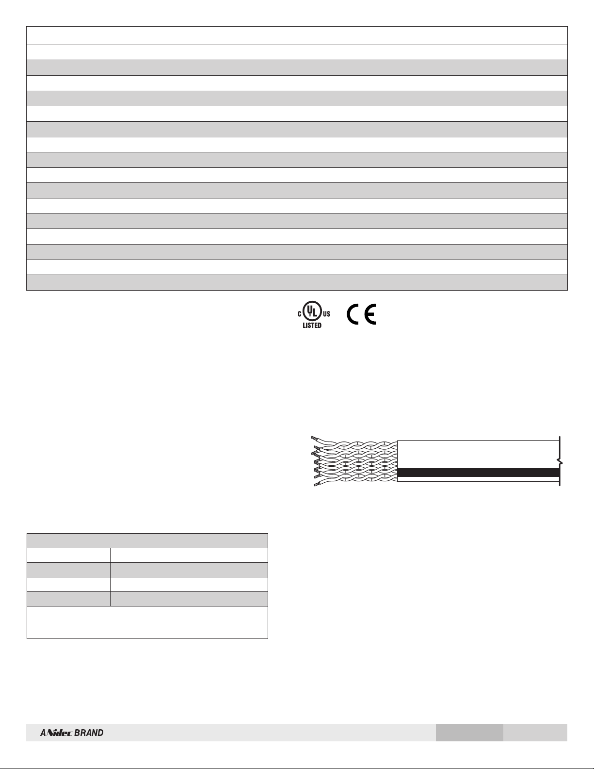
12.c-i) Strip cable and wires per illustration.
12.c-ii) Fold cable shield back over the claw.
12.c-iii) Remove the sealing nut, claw, and seal from the cable gland
and pass cable through the nut, claw and seal in the order in
which they were assembled on the encoder housing.
12.c-iv) Slide seal inside claw and pass wires through cable gland.
12.c-v) Connect wires according to pinout diagram on encoder label.
12.c-vi) Re-tighten sealing nut onto cable gland.
12.c-vii) Replace rear cover onto the encoder.
NOTE
The internal Terminal Strip is a Push-In type with 45° wire
entry. Wires can be removed from the Terminal Strip by
depressing the tab at each connection.
CAUTION
Trim wires to minimize excess length, as space inside the
encoder is limited.
13) Apply power to the encoder.
The AV44 encoder can be wired for single phase or two-phase
operation, either with or without complements, with or without markers.
See connector options and wiring diagrams.
CAUTION
When wiring for differential applications (A, /A, B, /B, Z, /Z),
A and /A should be wired using one twisted, shielded pair;
B and /B should be in a second pair, etc. Failure to use
complementary pairs (say, using A and B in a twisted pair)
will reduce noise immunity significantly.
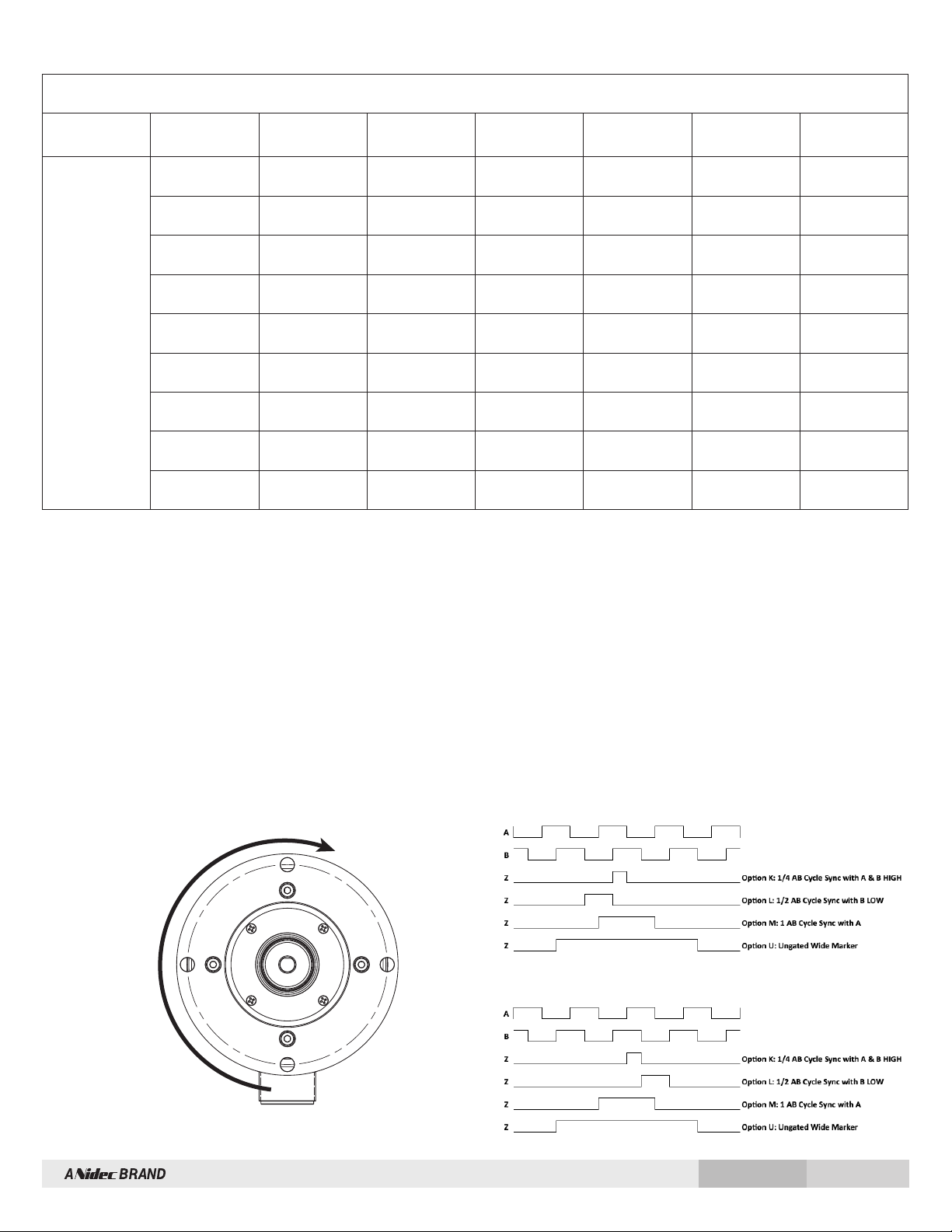
For encoder output that correctly reflects the direction of rotation, proper
phasing of the two output channels is important. Phase A channel leads
phase B channel for clockwise shaft rotation as viewed from the load
side of motor for standard phasing options. Follow instructions under
corrective installation as needed to reverse the direction of output or
purchase AV44 with reverse phasing (Connector options “B”, “3”).

AV44 Solid Shaft Incremental Encoder 3Rev: 003
CORRECTIVE ACTION FOR PHASE REVERSAL
If Encoder Direction is wrong:
1) Remove power.
2) Exchange wires on cable, either at encoder cable end, or at
speed controller end (but not both):
a.) Single Ended 2 Phase Wiring (see wiring diagram below)
Exchange A and B at the user end of the wires.
(/A & /B are not used)
b.) Differential 2 Phase Wiring (see wiring diagram below)
Exchange either A with /A in the phase A pair OR B with /B in
the phase B pair but NOT both.
3) Apply power.
4) Verify encoder feedback is correct, using hand rotation of shaft, or
jog mode of the speed controller.
Interconnecting cables specified in the wire selection chart are based on
typical applications. Refer to the “Wiring Diagrams” below for suggested
cable types. General electrical requirements are: stranded copper, 22
thru 16 gauge each twisted wire pair individually shielded with braid or
foil drain wire, 0.05 uF maximum total mutual or direct capacitance with
outer sheath insulator.
Our B37178 cable offers excellent noise performance, minimized power
supply loss and ultra-low capacitance for minimized signal loading. See
technical details on Spares & Accessories page.
Note: Maximum cable length (and line driver selection) is limited by
several factors: line driver protection, maximum RPM, PPR, output
voltage and cable capacitance. Line driver option “2” permits the
longest cable lengths (up to 300m at 45KHz). All AV44 line drivers
have full protection against external faults. These factors may dictate
maximum potential cable length.
FAULT-CHECK
After power-up and the rotor position is checked by the sensor, the Fault
Check LED will turn GREEN.
If the adaptive electronics reach their adjustment limit for any reason,
the Fault-Check alarm and LED will notify the drive and operator of an
impending failure. The LED will turn RED if the Adaptive Electronics
reach their adjustment limit. This output occurs before an actual
failure, allowing steps to be taken to replace the unit before it causes
unscheduled downtime.
If the alarm output and/or LED indicate a fault (RED):
If the alarm output and/or LED indicate a fault (RED) on a properly
mounted AV44, the encoder may be faulty and should be replaced.
An oscilloscope can also be used to verify proper output of the AV44
at the encoder connector itself and at the drive/controller cabinet. If
the outputs show large variations in the signals at steady speed (jitter
or “accordion effect”) this may be a sign of excess external magnetic
interference &/or the motor or shaft may be highly magnetized. Replace
any nearby magnetized material with non-magnetic material (aluminum,
stainless steel) (especially shafts). If the source of magnetic interference
cannot be eliminated, another encoder model may be required that
offers super-magnetic shielding such as Avtron Encoders HS45 (hollow
shaft) or AV45 (solid shaft).
If the LED is ORANGE (or blinking ORANGE):
This indicates that the outputs have shut off due to thermal overload.
The most likely cause is shorted outputs or undervoltage to the encoder.
Stop the system. Remove all output wires/connections
(A, /A, /B, B, Z, /Z). The LED should turn GREEN. If the LED does not turn
GREEN, the encoder is not receiving enough voltage at +V to properly
operate. Correct the input voltage problem. If the LED turns GREEN
once all outputs are disconnected, reconnect each output, one at a time,
monitoring for ORANGE LED. For partial/resistive short circuits, the LED
may take a few minutes to turn ORANGE. Once the shorted output(s)
are located, correct the shorting condition, and the encoder LED should
remain GREEN.
If equipped with the remote alarm option (Mod code 068), the /ALM
output will be asserted Low (~OV) whenever the LED is either RED or
ORANGE.
If the LED is OFF,
but power is being applied to the encoder, check the output voltage level
at A,/A,B,/B. If all outputs are Low (~OV), the connections to +V and
COM are reversed. Swap connections between +V and COM; the LED
should turn GREEN.

AV44 Solid Shaft Incremental Encoder 4Rev: 003
All Connector Options except “B” and “3” have Standard Phasing, A Leads B for CW rotation, viewed from load side of motor.
Note for Connector Options B and 3 with Reverse Phasing, the Phasing is inverted via Configuration; the Wiring and Pinout is the same as for Standard
Phasing (Connector option A or 2 respectively). For Connector Option with Reverse Phasing, B Leads A for CW rotation, viewed from load side of motor.
CW
Front of Encoder
Standard Phasing: A Leads B for CW Rotation (viewed from front of encoder)
Reverse Phasing: B Leads A for CW Rotation (viewed from front of encoder)
WIRING DIAGRAM / PINOUT
Connector Option “W”
(Cable)
Option “A”, “B”
(10-Pin MS)
Option “2”, “3”
(M23 12-Pin)
Option “T”
(M12 8-Pin)
Option “U”
(M12 8-Pin)
Option “Y”
(Terminal Strip) Ref Signal
Encoder Wiring
Green A 5 3 1 8 A
Yellow H 6 4 3 7 /A
Blue B 8 5 4 6 B
Gray I 1 6 5 5 /B
Orange C 3 7 6 3 Z
White J 4 8 8 4 /Z
Violet N/C 11 N/C N/C 9 /ALM”
Red D 12 2 2 1 +Vin
Black F 10 1 7 2 GND
* Remote alarm output for mod 068 code only

AV44 Solid Shaft Incremental Encoder 5Rev: 003
AV44 PART NUMBERS AND AVAILABLE OPTIONS
AV44 Shaft Flange Connector Marker Gating Line
Driver
PPR*
(Single)
PPR*
(Dual) Mods
A –
11mm w/key;
Ceramic
Bearings
E –
5/16” w/flat;
Ceramic
Bearings
B –
B10
Euroflange
(w/shaft “1”
or “A”)
P –
PY Flange
(w/shaft “5”
or “E”)
A –
10-pin MS,
w/o Plug;
Standard
Phasing
B –
10-pin MS,
w/o Plug;
Reverse
Phasing
2 –
M23/12
pin (CW
pin #s)
Standard
Phasing
3 –
M23/12
pin (CW
pin #s
Reverse
Phasing
T –
M12-8 pin
Turck Pinout
U –
M12-8 pin
U.S. Pinout
W –
M20 Cord
Grip w/ 0.5M
(20”) Cable
Y –
M20 Cord
Grip w/o
Cable
K –
¼ AB Cycle,
Sync w/A&B
High
L –
½ AB Cycle,
Sync w/B Low
M –
1 AB Cycle,
Sync w/A
U –
Raw Wide
Marker (Ungated)
1 –
6-30V in/out
(Hx–Hi Power)
2 –
6-30V in / 5V
out
3 –
5V in/out
AN –
256
AR –
512
AY –
1024
A3 –
2000
A4 –
2048
AT –
3072
AD –
4096
A2 –
8192
K1 –
10000
*Contact Factory for
Additional PPRs
XX –
None
000 –
No Special
Mods
9XX –
Custom
Cable
Length^
068 –
Remote
Alarm Output
070 –
Expanded
Temp Range
(-40 - +100C)
077 –
4500 - 6000
RPM
^ Custom Cable Length in
meters; whole meter increments
up to 99m
A V 4 4 X X
LINE DRIVER TABLE
LINE DRIVER OPTIONS
Electrical Specifications 1 2 3 Units
Input Voltage 6-30 6-30 5 VDC
Nom Output Voltage 6-30 5 5 VDC
Line Driver Hx Hx Hx
Output Resistance 75 75 75 ohms
Maximum Peak Current 800 800 800 mA
Maximum Average Current 200 200 200 mA
Voh Typ Vin-1V Vin-5V Vin-1V VDC
Vol Typ 0.4V 0.4V 0.4V VDC
Cable Drive Capacity 1000 [330] 1000 [330] 1000 [330] feet [m]
Protection
Reverse Voltage yes yes yes
Short Circuit yes yes yes
Transient yes yes yes
Mis-Wiring yes yes yes
Alarm +V out Output voltage equal to input voltage
Alarm Open collector, normally off, goes low on alarm, sink 100mA max, 50VDC max
Marker One per revolution, see marker gating option for width and gating

AV44 Solid Shaft Incremental Encoder 6Rev: 003
CABLES
SPECIFICATIONS TABLE
Input/Output Voltage Environmental
6-30 VDC IP66 housing with fully encapsulated electronics
Input Current (nominal for all Line Driver Options) Shaft Current Isolation
80 mA, no load 2700 VRMS ceramic bearings
Max Full Load Current Vibration
187 mA 10-2000 Hz, 17 Gs
Output Format Shock
A Quad B with marker (A,/A, B,/B, Z,/Z) 275 G, 6 mS duration
Frequency Range Axial Bearing Load
0 to 250 KHz @6 V & 1 m cable 500 N
PPR Radial Bearing Load
64 - 10000 standard (for other PPR needs, consult factory) 1200 N
Speed Weight
6000 RPM Max.** 2.5 lbs. [635 g] approx
Temperature Certifications
-30° to 85° C std, optional: -40° to 100° C CE, UL
B37178 cable offers excellent noise performance, minimized power
supply loss and ultra-low capacitance for minimized signal loading
The B37178 cable has the following features:
• -30°C to 80°C temp range
• 5 Twisted Pair
- 1 Pair 18 AWG
- 4 Pair 22 AWG
• Aluminum Mylar Shield & TC Braid Shield
**Max RPM is reduced with PPR>2,500. Consult factory with your
application
Proc. Cont. Eq.
E140849
UL Listed Cable Assemblies*
Cable Adapter Part Number
MS 10 Pin CBL1BBA1XPWyyy.y
M23 12 Pin CBL1BB21XPWyyy.y
M12 8 Pin CBL1BBT1XPWyyy.y
*All UL Listed cable assemblies must be 100’ long or less.
All UL Listed cable assemblies use cable B37150.
B37178 is not UL Listed for AV44.

AV44 Solid Shaft Incremental Encoder 7Rev: 003
+1 216-642-1230 | www.avtronencoders.com
Features and specifications subject to change without notice.
Nidec Industrial Solutions standard warranty applies. All dimensions are in mm [inch].
OUTLINE DRAWINGS
11mm SHAFT with 4mm KEY | B10 EUROFLANGE | CABLE GLAND
5/16” SHAFT WITH FLAT | PY FLANGE | 10 PIN MS CONNECTOR
11.000
10.975
7.0016x
33.084.4
112.00
30°11x
45°7x
77.5
85.00
84.95
2.0
5.020.0 4.0
101.50 100.00
0.2814x
3.978
0.3125
0.3120
Ø
3.32 0.94
4.41
2.78
0.50
2.500
2.498
0.06
0.28
4.00
Table of contents
Other Nidec Media Converter manuals

Nidec
Nidec Unidrive M200 User manual

Nidec
Nidec SI-Encoder V2 User manual

Nidec
Nidec Avtron HS45 Series User manual

Nidec
Nidec Avtron SMARTSafe XR67 User manual

Nidec
Nidec Avtron AV45 Series User manual

Nidec
Nidec Avtron AV6A User manual

Nidec
Nidec Avtron AV115 User manual

Nidec
Nidec Avtron Encoders HS44 User guide

Nidec
Nidec Avtron SAFETach III SV850 User manual
Popular Media Converter manuals by other brands

Lika
Lika HS58 user guide

SMC Networks
SMC Networks JXC 1 Series Supplementary Operation Manual

Transition Networks
Transition Networks CBFTF1011-100 user guide

MAJORITY
MAJORITY Castle Instruction guide

Extron electronics
Extron electronics DDS 402 Specification sheet

Sealey
Sealey AUTO SERVICE LINE TL95 instructions