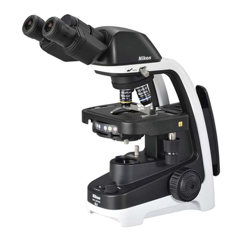
Nikon ECLIPSE Ni-E User manual

Specifications
Maintenance
and Storage
TroubleshootingAssembly
Upright Motorized Microscope
(Focusing Nosepiece System)
Instruction Manual
Assembly/Maintenance
M572 E 11.8.NF.1 (2/2)


Introduction
i
Introduction
Thank you for purchasing a Nikon product.
This instruction manual is written for users of the Nikon ECLIPSE Ni-E (Focusing Nosepiece System) microscope. To
ensure correct usage, read this manual carefully before operating this product.
●No part of this manual may be reproduced or transmitted in any form without prior written permission from Nikon.
●The contents of this manual are subject to change without notice.
●The equipment described in this manual may differ from the actual product in its appearance.
●Although every effort has been made to ensure the accuracy of this manual, errors or inconsistencies may remain. If
you note any points that are unclear or incorrect, please contact your nearest Nikon representative.
●Some of the equipment described in this manual may not be included in the set you have purchased.
●If you intend to use any other equipment with this product, read the manual for that equipment too.
●If this equipment is used in a manner not specified by the manufacturer, the protection provided by the equipment may
be impaired.
●Training: This product can be used without special training, provided that this manual is read thoroughly before use. Kindly
contact your nearest Nikon representative if you have any questions, find any errors, or wish to provide us with your
opinion.

Introduction
ii
Contents of the Manual
The instruction manual for ECLIPSE Ni-E (Focusing Nosepiece System) is provided in two volumes.
Operation
Safety Precautions
Components
Microscopy Operations
Before Microscopy
Operation Flowchart
IR-DIC (Infrared Ray Differential Interference
Contrast) Microscopy Procedure
Epi-fluorescence Microscopy Procedure
Individual Operations
Assembly/Maintenance (This manual)
Assembly
Troubleshooting
Maintenance and Storage
Specifications
Before reading the “Assembly/Maintenance” manual,
read the “Safety Precautions” in the “Operation”
manual.
Symbols Used in This Manual
The following symbols are used in this manual.
Symbols for Safety
WARNING
CAUTION
Highlights important information that should be noted for safety. Read “Safety Precautions” for details.
Other Symbols
Indicates information you should note or comply with to prevent defects or malfunction of this product.
Indicates information you should be aware of in using this product, as well as other useful information.

Summary of Contents
iii
Specifications
Maintenance
and Storage
TroubleshootingAssembly
Summary of Contents (See the next page for detailed contents.)
Introduction
Contents of the Manual
Symbols Used in This Manual
Assembly
Troubleshooting
Maintenance and Storage
Specifications

Contents
iv
Contents
Introduction .........................................................................................................................i
Contents of the Manual ....................................................................................................ii
Symbols Used in This Manual ..........................................................................................ii
Summary of Contents ....................................................................................................... iii
Assembly.................................................................................................. 1
1 ECLIPSE Ni-E (Focusing Nosepiece System) System Configuration.......................2
2 Components List .......................................................................................................4
3 Assembly Method......................................................................................................6
Introduction: Motorized Device Combination ...................................................................... 6
[1] Check input voltage................................................................................................. 7
[2] Unfasten the elevating section................................................................................ 7
[3] Attach the lamp. ...................................................................................................... 8
[4] Attach the lamphouse for dia-illumination............................................................... 8
[5] Attach the focusing nosepiece sub arm.................................................................. 9
[6] Attach the focusing nosepiece substage. ............................................................... 9
[7] Attach the polarizer turret (required for differential interference contrast
microscopy)........................................................................................................... 10
■Attaching optical module..................................................................... 10
[8] Attach the nosepiece..............................................................................................11
[9] Attach the condenser. ........................................................................................... 12
■Attaching the optical module to the condenser turret ......................... 12
[10] Attach the stage. ................................................................................................... 14
[10.1] Standard stage............................................................................... 14
[10.2] Motorized XY stage........................................................................ 15
[11] Attach the arm spacer. .......................................................................................... 19
[12] Attach the contact arm/standard arm.................................................................... 20
[13] Attach the connector box (optional). ..................................................................... 20
[14] Attach the epi-fluorescence cube turret and epi-fluorescence attachment
(required for epi-fluorescence microscopy). ......................................................... 21
■Attaching the filter cube/analyzer cube............................................... 22
■Replacing excitation and barrier filters................................................ 23
■Attaching a light shielding plate .......................................................... 23
[15] Attach the quadrocular tilting tube and DSC zooming port for quadrocular tube. 24
[16] Attach eyepieces................................................................................................... 25
[17] Attach the objective............................................................................................... 25
[17.1] Slider nosepiece ............................................................................ 25
[17.2] Single nosepiece............................................................................ 25
[18] Attach the camera and DS camera control unit (optional).................................... 26
[18.1] Attaching to DSC zooming port for quadrocular tube .................... 26
[18.2] Attaching to the quadrocular tilting tube......................................... 26
[19] Replace the ND filter (optional)............................................................................. 27
[20] Connect the motorized device cable..................................................................... 27
[21] Connect the power cord........................................................................................ 28
Contents
v
Troubleshooting..................................................................................... 29
1 Optical System and Operation ................................................................................30
1.1 General............................................................................................................. 30
1.2 Differential Interference Contrast Microscopy.................................................. 33
1.3 Epi-fluorescence Microscopy ........................................................................... 34
2 Electrical System.....................................................................................................35
2.1 General............................................................................................................. 35
2.2 Epi-fluorescence Microscopy ........................................................................... 38
Maintenance and Storage ..................................................................... 39
1 Replacing the Lamp ................................................................................................40
2 Cleaning ..................................................................................................................41
2.1 Cleaning Lenses............................................................................................... 41
2.2 Cleaning Parts Other than the Lens................................................................. 41
2.3 Cleaning Immersion Oil .................................................................................... 42
2.4 Decontaminating the Product........................................................................... 42
3 Restoring Microscope Data to Factory Default .......................................................42
4 Transportation (Using the Fastening Position Mode Switch) ..................................43
5 Storage....................................................................................................................43
6 Periodic Inspections (Charged)...............................................................................43
Specifications ........................................................................................ 45
1 Microscopy (Principles) ...........................................................................................46
2 Performance Properties ..........................................................................................46
3 Physical Properties .................................................................................................48

Contents
vi

1
Assembly
1
Chapter
1
Assembly
This chapter contains the system configuration diagram and components list for Ni-E (focusing nosepiece system), and
instructions on assembling the system.
Read appropriate notes such as CAUTION “9 Cautions on assembling and installing the product” at the beginning of the
separately provided instruction manual “Operation” or “4 Installation location” in “Notes on Handling the Product” in the
same manual before you work on assembling.
■Assembly tools provided with the microscope
•Hex driver x3: 2 mm across flats (for all three)
•Hex wrench x2: 3 and 4 mm across flats

Chapter 1 Assembly
2
Assembly
1 ECLIPSE Ni-E (Focusing Nosepiece System) System Configuration
D-FB
*1: Use with a motorized quadrocular tilting tube or motorized barrier filter wheel requires a motorized or intelligent
epi-fluorescence cube turret.
*2: Use with a motorized DSC zooming port requires a motorized quadrocular tilting tube.
Epi-fluorescence
cube turret*1
Epi-fluorescence
attachment
Centering
telescope CFI eyepiece
CFI60 Objective
DS camera head
Tube adapter for
quadrocular tube
DSC zooming port
Quadrocular
tilting tube*2
Camera cable
to DS-U3 or
DS-L3
Motorized shutter
connected to
Ni-E with a cable
Motorized
shutte
r
Motorized
shutter
Standard arm
DIC
slider
To c o n t ro l
box A
Motorized model:
connected to Ni-E
with RS-232C
cable
Fluorescence filte
r
cube/DIC
analyzer cube
FL/DIC
analyzer
Excitation
balancer
To connector
box
HG precentered
fiber illuminator
Ni-E main bod
y
Motorized barrier filter wheel
Motorized
excitation filter
wheel
Arm space
r
DIC
slider
Sliding
nosepiece
Single nosepiece
holder
CFI75 Objective
Focusing
nosepiece
sub arm
To N i- E ma i n
body
Contact arm
HG adapte
r
HG fibe
r
Mercury lamp
Various adapters
ENG mount camera
C mount camera
photomicrography
device

Chapter 1 Assembly
3
Assembly
POWER
Coarse
Fine
Ex Fine
XYSpeed
Constant Speed
Z Speed
Coarse
Fine
Ex Fine
+Y
-Y
-X +X
A.S
*3: DS-U3 DS Camera Control Unit cannot be connected by USB.
Ni-E main bod
y
Motorized XY stage
(requires motorized XY stage
adapter)
Polarize
r
turret
DS-L3/DS-U3
DS Camera
Control Unit
Motorized
shutter adapter
Motorized
shutter
To c o n t ro l
box A with
extention
cable
Control
box A
Lamphouse
Connector bo
x
PC
Standard stage
(requires FN1 stage
adapter)
To motorized XY
stage controller
with driver cable
Substage for focusing
nosepiece
To connector bo
x
with motorized
shutter connector
LWD condense
r
Joystic
k
controlle
r
Ergo controlle
r
Motorized ND filte
r
To connector
box
Optical fibe
r
illuminator
Motorized XY stage
controller Connected to
Ni-E with
USB cable*3
Connected to Ni-U main bod
y
or connector box with
camera trigger cable

Chapter 1 Assembly
4
Assembly
2 Components List
The ECLIPSE Ni-E (Focusing Nosepiece System) components are shown in the table below.
Depending on when you purchased the ECLIPSE Ni-E (Focusing Nosepiece System) product, there may be products not
yet available for use and products not listed that are already available for use. Contact your nearest Nikon representative
for details.
Device Device Name Model Remarks
Microscope main
body
ECLIPSE Ni-E
(12V 100W 100-240V external power
supply for illumination)
ECLIPSE Ni-E
Precentered lamphouse (12V 100W) NI-LH or NI-IRLH NI-IRLH is a lamphouse for IR
Halogen lamp (100W)
PHILIPS 7724
OSRAM HLX
64623
For NI-LH or NI-IRLH
Illuminator for
dia-illumination
Optical fiber illuminator
(12V 100W halogen lamp) LS-DWL-N
Sumita Optical Glass’s halogen light source optical fiber
illuminator
Requires fiber illumination adapter (model: NI-FIA)
Standard arm NI-SAM Use in combination with a manual device such as manual
nosepiece.
Arm
Contact arm NIE-CAM For motorized unit
Arm spacer 49mm NI-AMSS For Petri dish
Arm spacer Arm spacer 74mm NI-AMSL For thick samples such as live mouse
Binocular tube C-TB C-TBM mildew-proof type also available
Trinocular tube F C-TF C-TFM mildew-proof type also available
Trinocular eyepiece tube T C-TT
Ergonomic tube C-TE2
Quadrocular tilting tube NI-TT
Tube
Motorized quadrocular tilting tube NI-TT-E
DSC port for ergonomic binocular
tube C-TEP2
DSC zooming port for quadrocular
tube NI-RPZ
DSC port
Motorized DSC zooming port for
quadrocular tube NI-RPZ-E
Nikon DS camera head and other C mount camera are
connected. Nikon DS camera head control is DS-L3 or
DS-U3.
CFI eyepiece CFI
CFI UW
Eyepiece
Centering telescope C-CT
Sub arm Focusing nosepiece sub arm NI-FNA
Sliding nosepiece FN-S2N For CFI60 objective, DIC slider can be attached
Nosepiece Single nosepiece FN-MN-H For CFI75 objective, DIC slider can be attached
Objectives CFI objective CFI60、CFI75
Substage Substage for focusing nosepiece NI-SSF
Standard stage FN-3PS2 Requires FN1 stage adapter (model: NI-3PSA)
Stage Motorized XY stage NI-S-E Requires motorized XY stage adapter (model: NI-SA),
Dish holder (model: NI-SH-D) attachable
Condenser LWD condenser FN-C LWD D-C DIC module Dry, bright-field 4x auxiliary lens, and
diaphragm for the diagonal illumination attachable.
Epi-fluorescence cube turret NI-FLT6
Intelligent epi-fluorescence cube
turret NI-FLIT6-I
Epi-fluorescence
cube turret
Motorized epi-fluorescence cube
turret NI-FLT6-E
Filter cube, analyzer cube (visible light, infrared), and NI-FA
FL/DIC analyzer slider attachable.
Epi-fluorescence
attachment Epi-fluorescence attachment NI-FLEI D-FB Excitation Balancer attachable.
HG precentered fiber illuminator C-HGFI
Mercury lamp
illuminator Motorized HG precentered fiber
illuminator C-HGFIE
Polarizer unit Polarizer turret NI-PT Polarizer (VIS or IR) attachable
Motorized ND filter NI-ND-E Requires NIE-CB to be connected to Ni-E
Motorized excitation filter wheel NI-EXW-E Requires NIE-CB to be connected to Ni-E
Filter
Motorized barrier filter wheel NI-BAW-E

Chapter 1 Assembly
5
Assembly
Device Device Name Model Remarks
Motorized shutter NI-SH-E
To connect a second unit (on the dia-illumination side),
NIE-CB must be connected to Ni-E.
An NI-SHCS motorized shutter cable short is required for
connection.
Motorized shutter adapter for upright
epi-fl NI-SHAEP-U
Motorized shutter adapter for inverted
epi-fl TI-SHAEP-I Motorized excitation filter wheel (model: NI-EXW-E)
Shutter
Motorized shutter adapter for
dia-illumination NI-SHADI
Control box A NI-CTLA
DS-L3/DS-U3 camera control unit DS-L3
DS-U3
DS-L3 connects to Ni-E with USB cable
DS-L3/DS-U3 connects to Ni-E or control box with camera
trigger cable L3/U3 C-CTC
Connection with camera is with DS camera I/F cable
Connector box NIE-CB
Ergo controller NI-ERG Requires NIE-CB to be connected to Ni-E
Joystick controller NI-SJ Requires NIE-CB to be connected to Ni-E
Controller
Motorized XY stage controller TI-S-CON Requires NIE-CB to be connected to Ni-E
DSC support column NI-RPS
DSC retention
support DSC adapters A and B NI-RPSA
NI-RPSB
Tube adapter for
quadrocular tube Tube adapter for quadrocular tube C-TAQ
Attachable to quadrocular tilting tube. Attach a C mount
camera, ENG mount camera or a photomicrography device
via various adapters.
TV adapter TV adapter Y-T V
Y-T V55
Y-TV: attachable to the C-TF trinocular tube F or C-TT
trinocular tube T. Attach a C mount camera, ENG mount
camera or a photomicrography device via various adapters.
Y-TV55: attachable to the C-TF trinocular tube F or C-TT
trinocular tube T. Attach a C mount camera via a C mount
adapter 0.55x.

Chapter 1 Assembly
6
Assembly
3 Assembly Method
Introduction: Motorized Device Combination
The available combinations are specified when installing the following four types of motorized device to Ni-E with
contact arms connected. If an unallowed combination is used, an error message will be displayed when the power
is turned on. Therefore, use only in specified combination.
<Target device>
•Motorized/Intelligent epi-fluorescence cube turret
•Motorized barrier filter wheel
•Motorized quadrocular tilting tube
•Motorized DSC zooming port for quadrocular tube
Available motorized device combination with contact arm
1st level 2nd level 3rd level
Contact arm
Motorized quadrocular tilting tube
with/without Motorized DSC
zooming port (at rear)
— —
Contact arm Motorized/Intelligent
epi-fluorescence cube turret 1 - (Not connected) —
Contact arm Motorized/Intelligent
epi-fluorescence cube turret 1
Motorized quadrocular tilting tube
with/without Motorized DSC
zooming port (at rear)
—
Contact arm Motorized/Intelligent
epi-fluorescence cube turret 1
Motorized/Intelligent
epi-fluorescence cube turret 2 —
Contact arm Motorized/Intelligent
epi-fluorescence cube turret 1
Motorized/Intelligent
epi-fluorescence cube turret 2
Motorized quadrocular tilting tube
Motorized DSC zooming port
available/unavailable (at rear)
Contact arm Motorized/Intelligent
epi-fluorescence cube turret 1 Motorized barrier filter wheel —
Contact arm Motorized/Intelligent
epi-fluorescence cube turret 1 Motorized barrier filter wheel
Motorized quadrocular tilting tube
Motorized DSC zooming port
available/unavailable (at rear)
<Error display>
(1) The message shown on the right side is displayed
on the front display panel of the Ni-E main body.
_*_Illegal_Connection_*
[ER3]
(2) The power LED on the front of the contact arm blinks
at 0.2 second interval. (normally ON consecutively)
5
4
3
2
1
50
60
70
Power LED blinking
(3) A buzzer beeps repeatedly.

Chapter 1 Assembly
7
Assembly
Assemble the device in accordance with the following procedure.
Precautions on cable connection
Cables are required for some motorized devices.
Be sure to turn off the power to the microscope and peripheral devices before starting cable connection.
Cable connections are described in each assembly step. Nikon recommends connecting a cable at the end of the assembly.
See “20 Connect the motorized device cable” for information about connector positions.
Setting information regarding motorized devices
Set the information on the optical elements or attached motorized devices on the microscope setup screen for the
DS-L3 DS Camera Control Unit. (See Chapter 3 “20 Operation on DS-L3 - 20.1 Setting Up the Microscope” in the
“Operation”.)
Assembly referencing the Ni-E Focusing Stage System instruction manual
See the instruction manual for the Ni-E focusing stage system (“Assembly/Maintenance”) for details on the assembly
method of the following motorized units.
yMotorized ND filter wheel
yMotorized barrier filter wheel
yMotorized excitation filter wheel
The installation of motorized shutter is performed by Nikon. Contact your Nikon representative when necessary.
1
Check input voltage.
Check the input voltage indicated on the back of control
box A. Use the microscope only if the indicated input
voltage matches the power supply voltage for the area in
which the microscope will be used.
WARNING
If the indicated voltage and the supplied voltage differ, do
not attempt to use the microscope. Contact your nearest
Nikon representative to seek advice.
Ni-E CONTACT
ARM1
LAMP
FASTENING
POSITION SW
OFF ON
100-240V~ 5A 50/60Hz
MODEL NI-CTLA
MADE IN JAPAN
This device complies with Part
15 of the FCC Rules. Operation
is subject to the following
two conditions:
(1) this device may not cause
harmful interference, and
(2) this device must accept any
interference received,
including interference that
may cause undesired
operation.
This Class A digital apparatus
complies with Canadian ICES-003.
Cet appareil numérique de la
classe A est confirme à la
norme NMB-003 du Canada.
540001
Checking the input voltage
2
Unfasten the elevating section.
Tool: flathead screwdriver
Loosen and remove the tightening screw at the front of
the elevating section.
IN
ND
8ND
32 NCB
11
OUT
Unfastening the elevating section
Input voltage
label
Tightening screw

Chapter 1 Assembly
8
Assembly
3
Attach the lamp.
Tool: Hex wrench (3 mm across flats)
Lamp handling precautions
Avoid touching the glass surface of the lamp with
your bare hands.
(1) Loosen a lamphouse-cover fixing screw and lift up
the cover to remove it.
(2) Push in the lamp clamp lever to open the socket pin
hole. Attach the lamp while holding down the lever.
Put the lamp clamp lever back to its original position.
Specified lamp: PHILIPS7724
or OSRAM HLX64623
(3) Reattach the cover back to its original position and
tighten the lamphouse-cover fixing screw.
Removing the lamphouse cover
Attaching the lamp
4
Attach the lamphouse for dia-illumination.
Tool: Hex driver (2 mm across flats)
(1) Insert the lamphouse at the rear of the microscope
and tighten the fixing screws.
(2) Connect the dia-illumination lamphouse cable to the
LAMP connector of the control box A using a relay
cable.
IN
ND
8ND
32 NCB
11
OUT
EPI
SHUTT
CONTACT ARM2
USB
DSC
HGFIE
BOX
MODEL ECLIPSE Ni-E
NIKON CORPORATION
TOKYO, JAPAN
MADE IN JAPAN
Thisdevice complies with Part 15 of the FCC Rules. Operation is subject to the following two conditions:
(1)this device may not cause harmful interference, and
(2)this device must accept any interference received, including interference that may cause undesired operation.
ThisClass A digital apparatus complies with Canadian ICES-003.
Cetappareil numérique de la classe A est confirme à la norme NMB-003 du Canada.
910001
1.
2.
3.
Do not touch the lamphouse while the lamp is lit.
The surface of the lamphouse becomes hot when the
lamp is on.
Turn off the power and allow the lamp and lamohouse
to cool enough before replacing the lamp.
Wait for at least 30 minutes after turning off the
lamp.
Use 12V100W HALOGEN lamp only.
HALOGEN 12V100W
952001
NI-LH
CAUTION!
-High Temperature-
JAPAN
Securing the dia-illumination lamphouse
Lamphouse
fixing screw
Fixing screw
Lamphouse
cover
Insert the hex wrench and
loosen the fixing screw.
Lamp
clamp lever
Lamp
Lamphouse fixing screw

Chapter 1 Assembly
9
Assembly
5
Attach the focusing nosepiece sub arm.
The focusing nosepiece sub arm attachment position to the elevating section of the main body differs depending
on the arm spacer to be attached in step 11.
NI-AMSS Arm Spacer 49 mm: Attach the sub arm to the lower position.
NI-AMSL Arm Spacer 74 mm: Attach the sub arm to the upper position.
Check the fixing screw positions in the illustrations on the right side. Attachment procedure is the same.
Tool: Hex wrench (3 mm across flats)
Place the groove on the focusing nosepiece sub arm on
the reference bar in the main body elevating section.
Move the sub arm to the left, and tighten the fixing
screws (x4) provided by the sub arm while pushing it
against the reference surface of the elevating section.
ND
8ND
32 NCB
11
OUT
(Fixing position when the NI-AMSS Arm Spacer
49 mm is attached)
ND
8ND
32 NCB
11
OUT
(Fixing position when the NI-AMSL Arm Spacer
74 mm is attached)
Attaching the focusing nosepiece sub arm
6
Attach the focusing nosepiece substage.
Tools: Hex wrench (3 mm across flats)
(1) Place the focusing nosepiece substage on the main
body base while aligning it with the four fixing screw
hole positions, and then tighten the screws (x4)
provided with the substage using a hex wrench.
ND
8ND
32 NCB
11
OUT
Attaching the substage
Sub arm fixing
screw position
(x4)
Reference
guide bar
Groove
Sub arm fixing
screw position
(x4)
Reference
guide bar
Groove
Focusing
nosepiece
substage
fixing screw

Chapter 1 Assembly
10
Assembly
7
Attach the polarizer turret (required for differential interference contrast microscopy).
Tool: Hex driver (2 mm across flats)
Hex wrench (3 mm across flats)
(1) Put the polarizer turret with optical module attached
(according to the following procedure) on the field
lens of the microscope base and fix it using the
provided fixing screws (x2).
(2) Turn the knurled ring on the right of the polarizer
turret to adjust the field of view so that the field of
view becomes darkest. When adjustment is
complete, tighten the polarizer fixing screw.
Attaching the polarizer turret
■Attaching optical module
The polarizer turret has four holes with the FN-P
polarizer for visible range (λ=430 nm to 770 nm) and the
FN-IRP polarizer for infrared ray (lambda=850 nm to 950
nm) attached. The remaining two holes are empty and a
33 mm diameter filter can be attached.
The NCB 11 filter is attached as standard.
(1) Distribute IR polarizers to the upper section
(bandpass filter + 1/4 lambda plate) and lower
section.
(2) Insert the adjustment tool for the 1/4 lambda plate
orientation provided with the polarizer turret into the
lower section of the IR polarizer while aligning the
notch of the adjustment tool for the 1/4 lambda plate
orientation with the protrusion on the lower section
of the IR polarizer.
Separation of the IR polarizer
Attaching the adjustment tool for the 1/4 lambda
plate
(3) Align the index (white dot) on the knurled ring on the
right of the polarizer turret with the center line of the
scale. Insert the assembled IR polarizer into the
polarizer turret in the orientation shown in the figure.
O
Attaching the polarizer
Polarizer fixing
screw
Knurled ring Polarizer turret fixing
screw
Upper section (bandpass filter
+ 1/4 lambda plate)
Lower
section
A
djustment
tool for the
1/4 lambda
plate
orientation
Notch
Protrusion
Lower section
of the polarizer
(1)
(2)
Notch of the
polarizer
White spot
indication and
center line

Chapter 1 Assembly
11
Assembly
8
Attach the nosepiece.
The procedures are the same for both the sliding
nosepiece and single nosepiece.
Tool: Hex driver (2 mm across flats)
(1) Insert a hex drive through the hole on the right side
of the focusing nosepiece sub arm, and then loosen
the M4 hexagon hole set screw.
(2) Insert the sliding nosepiece or single nosepiece into
the dovetail on the focusing nosepiece sub arm.
(3) Insert it to the end and secure it with the M4
hexagon socket head set screw.
When the arm spacer has already been
attached
If you try to attach the nosepiece to the main body
to which the arm spacer has already been
attached, the set screw for fixing the nosepiece
may be covered by the arm spacer and the set
screw cannot be tightened depending on the
elevating section of the microscope.
In this case, turn on the power to the microscope,
rotate the focus knob to slightly lower the
elevating section, and then reveal the set screw.
JAPAN
FN-S2N
Attaching the nosepiece
(Example of the slider nosepiece)
M4 hexagon socket
head set screws

Chapter 1 Assembly
12
Assembly
9
Attach the condenser.
(1) Turn the condenser focus knob until the condenser
holder of the focusing nosepiece substage reaches
the bottom.
(2) Fit the round dovetail of the condenser to the
condenser holder so that the Nikon nameplate faces
front and tighten the condenser clamp screw of the
condenser holder.
Securing the condenser
■Attaching the optical module to the condenser turret
The turret has one empty hole and three holes for attaching the optical module.
Attach the DIC module or diaphragm for the diagonal illumination for differential interference contrast microscopy
DIC modules [D-C DIC N1 DRY], [D-C DIC N2 DRY], and, [D-C DIC NR DRY] are available. Select the DIC
module appropriate for the objective. (See the following table.) If the combination is not correct, differential
interference contrast image cannot be obtained or the contrast decreases significantly. To support for particular
purposes, modules for higher contrast or resolution are available. Note, however, that in principle the contrast
contradicts the resolution of the differential interference contrast image (the higher the contrast, the lower the
resolution).
Tool: Hex driver (2 mm across flats)
(1) Loosen the cover fixing screws (x2) on the top of the
condenser using a hex driver and remove the cover.
(2) An opening to attach/detach the DIC module
appears. Attach the DIC module from that opening
and tighten the fixing screws..
A. S
0
Attaching the optical module
•To attach DIC module N1
Turn the turret so that you can see the [OBL] sticker on the side of the turret. The attachment position of DIC
module N1 will come to the opening.
•To attach DIC module N2
Turn the turret so that you can see the [O] sticker on the side of the turret. The attachment position of DIC
module N2 will come to the opening.
•Attaching 4x lens for low magnification bright-field microscopy
Attach to mount position of DIC module N1. 4x is not indicated on the turret. Remove it when observing with an
objective greater than 4x magnification.
•Attaching diagonal illumination diaphragm
Turn the turret so that you can see the [N1] sticker on the side of the turret. The attachment position of the
diaphragm for the diagonal illumination will come to the opening. Attach the diaphragm for the diagonal
illumination while fitting its notch to the pin.
Condenser
focus knob Condenser
clamp screw
Optical module attachment
section cove
r
Optical module
Sticker
Optical module
fixing screw
Other manuals for ECLIPSE Ni-E
3
Table of contents
Other Nikon Microscope manuals

Nikon
Nikon Eclipse L200A User manual

Nikon
Nikon DIAPHOT 300 User manual

Nikon
Nikon Eclipse E600 User manual

Nikon
Nikon SMZ-1 User manual

Nikon
Nikon ECLIPSE L200ND / ECLIPSE L200N User manual

Nikon
Nikon LABOPHOT2-POL User manual

Nikon
Nikon TSM User manual

Nikon
Nikon SMZ1000 User manual

Nikon
Nikon Eclipse E400 User manual

Nikon
Nikon SMZ460 User manual

Nikon
Nikon OPTIPHOT-POL User manual

Nikon
Nikon Eclipse TS100 User manual

Nikon
Nikon Alphaphot User manual

Nikon
Nikon Live Cell 2 User manual

Nikon
Nikon Eclipse E400 POL User manual

Nikon
Nikon LABOPHC-POL User manual

Nikon
Nikon A1+ Manual

Nikon
Nikon Eclipse E400 POL User manual

Nikon
Nikon Ee1078 User manual

Nikon
Nikon SMZ1500 User manual