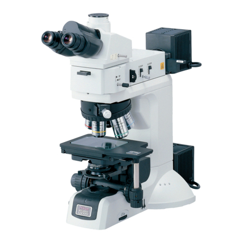
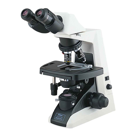
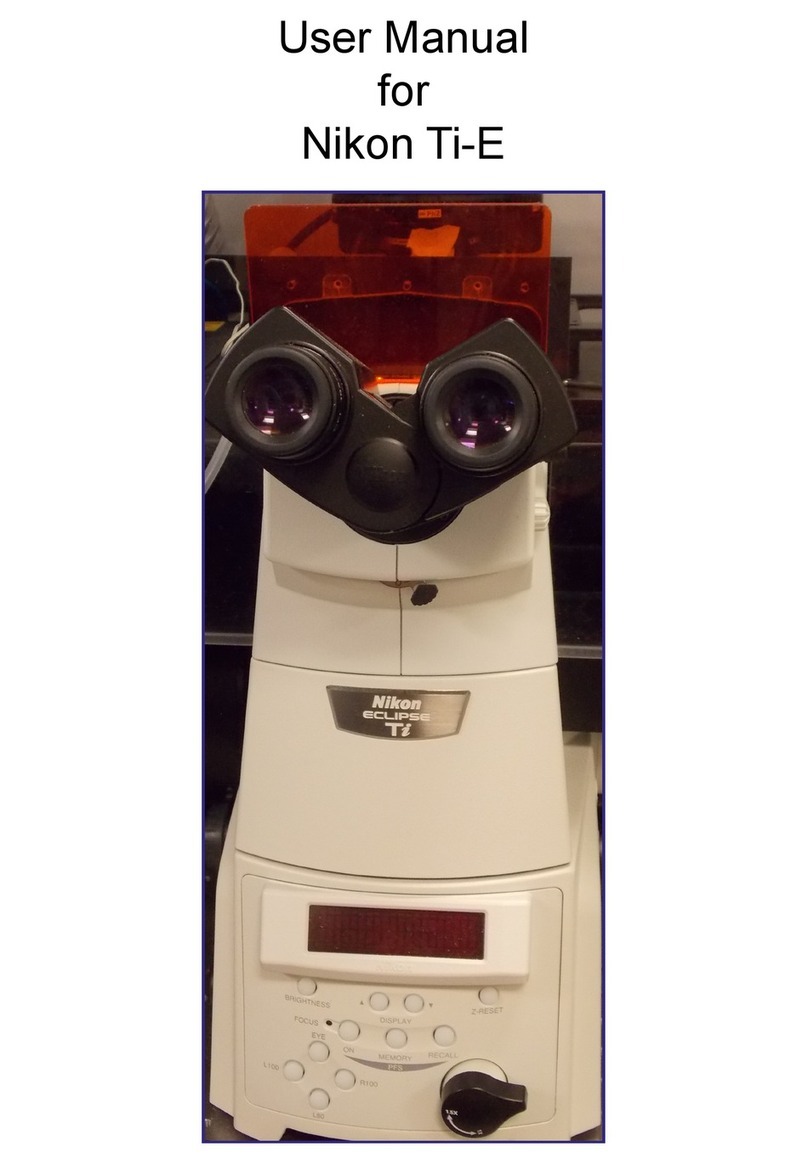
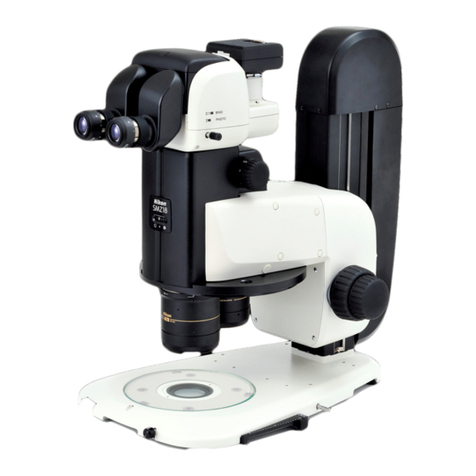
Nikon ECLIPSE Ti2-U User manual

M702
E21.2.NF.8 (1/2)
*M702EN08*
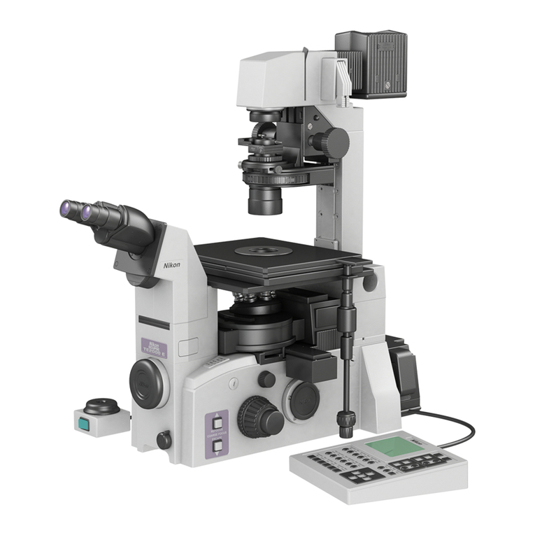
Inverted Research Microscope
Instruction Manual


Introduction
i
Introduction
Thank you for purchasing a Nikon product.
This instruction manual is intended for users of the Nikon Inverted Research Microscope ECLIPSE Ti2-U.
To ensure correct usage, read this manual carefully before operating this product.
• No part of this manual may be reproduced or transmitted in any form without prior written permission
from Nikon.
• The contents of this manual are subject to change without notice.
• The equipment described in this manual might differ from the actual product in its appearance.
• Although every effort has been made to ensure the accuracy of this manual, errors or inconsistencies
might remain. If you notice any points that are unclear or incorrect, please contact your local Nikon
representative.
• Some of the equipment described in this manual may not be included in the set you have purchased.
• If you intend to use any other equipment with this product, read the manual for that equipment too.
• If the equipment is used in a manner not specified by the manufacturer, the protection provided by the
equipment might be impaired.
• Products and company names mentioned in this manual are trademarks or registered trademarks of
their respective holders.

Contents
ii
Contents
Introduction......................................................................................................................................................i
Safety Precautions .......................................................................................................................................vii
Meaning of Symbols Used on the Product................................................................................... vii
WARNING and CAUTION Symbols Used in This Manual.......................................................... viii
WARNING .............................................................................................................................. ix
CAUTION ............................................................................................................................. xiv
Handling of This Product...........................................................................................................................xvii
Chapter 1 Names of Parts and Their Functions .........................................................................................1
1.1 System Configuration and Names of Components........................................................................2
1.2 Nomenclature and Functions .........................................................................................................4
1.2.1 Dia-illumination Section ....................................................................................................4
1.2.2 Condenser Unit and Polarizer...........................................................................................5
1.2.3 Tube and Eyepiece ...........................................................................................................6
1.2.4 Tube Base Unit .................................................................................................................6
1.2.5 Stage.................................................................................................................................7
1.2.6 Nosepiece .........................................................................................................................8
1.2.7 Objectives .........................................................................................................................8
1.2.8 FL Turret and Analyzer......................................................................................................9
1.2.9 Epi-fluorescence Attachments ........................................................................................10
1.3 Operation Sections of the Microscope Main Body .......................................................................12
1.3.1 Front Operation Panel ....................................................................................................12
1.3.2 Right and Left Operation Panels.....................................................................................12
1.3.3 Power Switch ..................................................................................................................13
1.3.4 AC Adapter and Power Cord ..........................................................................................13
Chapter 2 Microscopy .................................................................................................................................15
2.1 Diascopic Bright-field (BF) Microscopy ........................................................................................16
2.2 Diascopic Phase Contrast (Ph) Microscopy.................................................................................18
2.3 Diascopic DIC / IMSI Microscopy.................................................................................................20
2.4 Episcopic Fluorescence (Epi-FL) Microscopy..............................................................................22
2.5 Diascopic Dark-field (DF) Microscopy..........................................................................................24
2.6 NAMC Microscopy .......................................................................................................................26
Chapter 3 Usage of Components ...............................................................................................................29
3.1 Power-related Operation ..............................................................................................................30
3.2 Optical Parts in the Microscope Main Body .................................................................................31
3.2.1 Switching the Output Port ...............................................................................................31
3.2.2 Switching the Magnification of the Device with the Intermediate Magnification Dial......32
3.3 Using the Dia-illumination Section ...............................................................................................33
3.3.1 Opening/Closing the Dia-Illumination Shutter.................................................................33
3.3.2 Using Diascopic Illumination...........................................................................................33
3.3.3 Adjusting the Dia Field Diaphragm .................................................................................34
3.3.4 Using a Filter for Dia-illumination....................................................................................35
3.3.5 Using the Dia-illumination Pillar ......................................................................................36

Contents
iii
3.3.6 Operating the Contrast Shield (Optional) .......................................................................37
3.3.7 Using the D-LH/LC Precentered Lamphouse .................................................................38
3.4 Using the Condenser Section ......................................................................................................41
3.4.1 Selecting a Suitable Condenser .....................................................................................41
3.4.2 Elevating the Condenser ................................................................................................42
3.4.3 Adjusting the Position of the Condenser (Centering) .....................................................42
3.4.4 Using an Oil Immersion Condenser Lens.......................................................................43
3.4.5 Adjusting the Diascopic Aperture Diaphragm .................................................................44
3.4.6 Switching the Condenser Module ...................................................................................45
3.4.7 Adjusting the Ph Module Position ...................................................................................47
3.4.8 Adjusting the NAMC Module...........................................................................................48
3.4.9 Using the ELWD-S Condenser .......................................................................................50
3.5 Using the Polarizer and Analyzer .................................................................................................51
3.5.1 Using the Polarizer..........................................................................................................51
3.5.2 Using the Analyzer..........................................................................................................53
3.6 Using the Tube and the Objective................................................................................................54
3.6.1 Adjusting the Angle of the Binocular Part (ER tube).......................................................54
3.6.2 Adjusting the Diopter of the Eyepiece.............................................................................55
3.6.3 Adjusting Interpupillary Distance ....................................................................................56
3.6.4 Operating the Centering Telescope ................................................................................56
3.7 Using the Tube Base Unit ............................................................................................................57
3.7.1 Switching the Optical Path of the Tube Base Unit (Tube Base Unit with Port)...............57
3.8 Using the Stage............................................................................................................................58
3.8.1 Setting a Sample on the Manual Stage ..........................................................................58
3.8.2 Setting a Sample on the Plain Stage/Gliding Stage .......................................................59
3.8.3 Moving a Sample on the Stage.......................................................................................60
3.9 Using the Nosepiece ....................................................................................................................61
3.9.1 Turning the Nosepiece to Switch the Objective ..............................................................61
3.9.2 Placing the DIC Prism into the Optical Path ...................................................................61
3.10 Using the Objective ......................................................................................................................62
3.10.1 Adjusting the Objective with the Correction Collar .........................................................62
3.10.2 Using Oil Immersion Objectives......................................................................................64
3.10.3 Using a Water Immersion Objective ...............................................................................65
3.10.4 Using an Objective with a Diaphragm.............................................................................66
3.11 Using the Focusing Device ..........................................................................................................67
3.11.1 Focusing on the Sample .................................................................................................67
3.11.2 Using the Coarse-Focus Knob Torque Adjustment Ring ................................................68
3.11.3 Using the Objective Refocusing Lever ...........................................................................69
3.12 Using the FL turret........................................................................................................................70
3.12.1 Switching the Filter Cube................................................................................................70
3.12.2 Using the Shutter of the FL Turret ..................................................................................70
3.12.3 Selecting Filter Cubes.....................................................................................................71
3.13 Using the Epi-fluorescence Attachment .......................................................................................72
3.13.1 Adjusting the Aperture Diaphragm of the Epi-fluorescence Attachment.........................72
3.13.2 Using the Filter Slider......................................................................................................73
3.13.3 Using the Field Diaphragm Slider ...................................................................................74
3.13.4 Switching the Optical Path of the Main Branch ..............................................................76
3.14 Using a Back Port Unit (Optional) ................................................................................................77

Contents
iv
3.15 Using a Centering C-mount Adapter ............................................................................................78
Chapter 4 Microscopy Techniques ............................................................................................................79
4.1 Details of Diascopic Bright-field (BF) Microscopy ........................................................................80
4.1.1 Principles of BF Microscopy ...........................................................................................80
4.1.2 Optical Elements Required for BF Microscopy...............................................................81
4.1.3 Combination of Optical Elements ...................................................................................82
4.2 Details of Phase Contrast (Ph) Microscopy .................................................................................83
4.2.1 Principles of Ph Microscopy............................................................................................83
4.2.2 Optical Elements Required for Ph Microscopy ...............................................................84
4.2.3 Combination of Optical Elements ...................................................................................86
4.3 Details of Diascopic DIC and IMSI Microscopies.........................................................................87
4.3.1 Principles of DIC Microscopy..........................................................................................87
4.3.2 Optical Elements Required for DIC Microscopy .............................................................88
4.3.3 Combination of Optical Elements ...................................................................................90
4.4 Details of Episcopic Fluorescence (Epi-FL) Microscopy..............................................................94
4.4.1 Principles of Epi-FL Microscopy......................................................................................94
4.4.2 Optical Elements Required for Epi-FL Microscopy .........................................................95
4.4.3 Combination of Optical Elements ...................................................................................96
4.5 Details of Diascopic Dark-field (DF) Microscopy..........................................................................97
4.5.1 Principles of DF Microscopy ...........................................................................................97
4.5.2 Optical Elements Required for DF Microscopy...............................................................97
4.5.3 Combination of the Optical Elements Required for DF Microscopy ...............................99
4.6 Details of NAMC Microscopy .....................................................................................................100
4.6.1 Principles of NAMC Microscopy ...................................................................................100
4.6.2 Optical Elements Required for NAMC Microscopy.......................................................101
4.6.3 Combination of Optical Elements .................................................................................102
Chapter 5 Troubleshooting .......................................................................................................................103
5.1 Troubleshooting for Microscopy Techniques..............................................................................104
5.1.1 Common Microscopy Troubles .....................................................................................104
5.1.2 Troubles in BF Microscopy ...........................................................................................107
5.1.3 Troubles in Ph Microscopy............................................................................................109
5.1.4 Troubles in DIC and IMSI Microscopies .......................................................................110
5.1.5 Troubles in Epi-FL Microscopy ..................................................................................... 111
5.1.6 Troubles in DF Microscopy ........................................................................................... 111
5.1.7 Troubles in NAMC Microscopy .....................................................................................112
5.2 Troubleshooting for the Units .....................................................................................................113
5.2.1 Microscope Main Body .................................................................................................113
5.2.2 Problems with the Dia-illumination Section ..................................................................113
5.2.3 Pillar for Dia Illumination and Condenser .....................................................................114
5.2.4 Stage.............................................................................................................................114
5.2.5 Nosepiece and Focusing Device ..................................................................................114
5.2.6 Epi-fluorescence Attachment ........................................................................................114
Chapter 6 Maintenance and Storage of the Device ................................................................................115
6.1 Cleaning the Device ...................................................................................................................116
6.1.1 Cleaning the Lenses .....................................................................................................117
6.1.2 Cleaning Parts other than Lenses ................................................................................117

Contents
v
6.1.3 Cleaning Off Immersion Oil...........................................................................................117
6.1.4 Decontaminating the Product .......................................................................................117
6.2 Storing the Product ....................................................................................................................118
6.3 Regular Inspection (Charged) ....................................................................................................118
Chapter 7 Assembly of the Devices.........................................................................................................119
7.1 Ti2-U System Configuration .......................................................................................................121
7.2 List of Components ....................................................................................................................123
7.3 Installing the Microscope Main Body (Base)..............................................................................127
7.3.1 Removal and Installation ..............................................................................................127
7.4 Mounting the Tube Base Unit.....................................................................................................128
7.5 FL Turret (Required for Epi-FL Microscopy)...............................................................................129
7.5.1 Attaching an FL Turret ..................................................................................................129
7.5.2 Mounting a Filter Cube .................................................................................................130
7.5.3 Replacing an Excitation Filter, a Barrier Filter, and a Dichroic Mirror ...........................131
7.5.4 Attaching Optical Elements to the C-FL-HQ Filter Cube ..............................................135
7.6 Attaching a Nosepiece ...............................................................................................................137
7.7 Mounting a Stage .......................................................................................................................138
7.7.1 Mounting the Stage.......................................................................................................138
7.7.2 Attaching a Stage Handle (Manual Stage Only)...........................................................139
7.7.3 Removing a Fixing Tool of the Stage ............................................................................141
7.7.4 Restriction on Stage Strokes (Manual Stage Only) ......................................................142
7.8 Mounting a Diascopic Illumination Pillar and a Lamphouse ......................................................143
7.8.1 Mounting an Illumination Pillar......................................................................................143
7.8.2 Attaching the Condenser Holder...................................................................................144
7.8.3 Attaching a Fixed Filter for Dia-illumination ..................................................................145
7.8.4 Attaching a Filter Slider for Dia Illumination (Optional).................................................146
7.8.5 Attaching a Motorized Dia-Illumination Shutter (Optional)............................................147
7.8.6 Mounting a Lamphouse for Dia-illumination .................................................................148
7.8.7 Replacing a Dia-Illumination Lamp (Precentered Lamphouse only) ............................149
7.9 Attaching a Contrast Shield (Optional).......................................................................................150
7.10 Attaching an Analyzer and a Polarizer (Required for DIC Microscopy) .....................................151
7.10.1 Attaching an Analyzer ...................................................................................................151
7.10.2 Attaching a Polarizer.....................................................................................................152
7.11 Attaching a Condenser...............................................................................................................153
7.11.1 Preparation for Attaching a Condenser.........................................................................153
7.11.2 Attaching a Condenser Turret (System Condenser).....................................................154
7.11.3 Attaching an ELWD-S Condenser ................................................................................157
7.11.4 Attaching a DF Condenser ...........................................................................................157
7.11.5 Attaching a High NA Condenser ...................................................................................158
7.12 Attaching the Tube and Eyepieces ............................................................................................160
7.13 Attaching an Epi-fluorescence Attachment ................................................................................161
7.13.1 Mounting an EPI-FL Module (TI2-LA-FL-2) ..................................................................161
7.13.2 Attaching a Field Diaphragm Slider ..............................................................................165
7.14 Attaching a Camera Device .......................................................................................................166
7.14.1 Attaching a Camera Device to the Side Port (Microscope Main Body)........................166
7.14.2 Attaching a Camera Device to the Side Port on the Tube Base Unit ...........................168
7.14.3 Attaching the Back Port Unit (Optional)........................................................................169
7.15 Connection of Each Cable .........................................................................................................170
Contents
vi
7.15.1 Position of Each Connector ..........................................................................................170
7.15.2 Clamping Cables...........................................................................................................171
7.16 Attaching Objectives ..................................................................................................................172
7.16.1 Attaching CFI60 Objectives ..........................................................................................172
7.16.2 Parfocal Adjustment of Objectives without Correction Collar .......................................173
7.17 Attaching a Specimen Holder.....................................................................................................175
7.17.1 Attaching a Specimen Holder for the Manual Stage.....................................................175
7.17.2 Attaching a Stage Ring .................................................................................................175
7.18 Moving the Microscope ..............................................................................................................176
Chapter 8 Specifications...........................................................................................................................177
8.1 Principles of Operation...............................................................................................................178
8.2 Performance Properties .............................................................................................................179
8.3 Physical Properties ....................................................................................................................183

Safety Precautions
vii
Safety Precautions
Although this product is designed and manufactured to be completely safe during use, incorrect usage or
failure to follow the safety instructions provided may cause personal injury or property damage. To ensure
correct usage, carefully read this manual and the instruction manuals of products used together before using
the product. Be sure to read and observe the safety precautions described at the beginning of each manual.
Do not discard this manual and keep it handy for easy reference.
Meaning of Symbols Used on the Product
The symbol appearing on the product indicates the need for caution at all times during use. Always refer to
the instruction manual and read the relevant instructions before manipulating any part to which the symbol
has been affixed.
Symbol Description
Biohazard
This symbol label is attached on the top or front surface of the stage to remind the user of the
following precautions:
• Spillage of a specimen from a vessel onto the microscope, presents a biohazard risk.
• To avoid biohazard contamination, do not touch the contaminated portion with your bare hands.
• Decontaminate the contaminated portion according to the standard procedure of your laboratory.
Manual stage Plain stage Gliding stage
Caution for heat
This symbol label is attached on the top surface of the optical path cover on the top of the
illumination pillar, on the top surface of the TI2-D-SF filter slider for dia illumination, and on the
back surface of the D-LH/LC precentered lamphouse. When the D-LH/LC is used as the
dia-illumination source, this symbol reminds the user of the following precautions:
• The lamp and lamphouse, the top surface of the optical path cover, and the top surface of the
filter slider for dia-illumination become hot while the lamp is lit or immediately after it goes out.
• To avoid the risk of burns, do not touch the lamp or lamphouse, the top surface of the optical
path cover, or the top surface of the filter slider for dia-illumination while the lamp is lit or
immediately after it goes out.
• Make sure the lamp, the lamphouse, and the air vents of the HG precentered fiber illuminator
have cooled sufficiently before attempting to replace the lamp.
S.
F.
The top surface of the optical path
cover
S.
F.
The top surface of
the TI2-D-SF filter slider for dia
illumination
Rear surface of the D-LH/LC
precentered lamphouse
When a TI2-D-LHLED LED
lamphouse for dia-illumination is used
When the TI2-D-SF filter slider for dia illumination and the D-LH/LC
precentered lamphouse are used
Biohazard symbol
Biohazard
symbol Biohazard
symbol
Hot surface
symbol
Hot surface
symbol
Hot surface
symbol

Safety Precautions
viii
Symbol Description
Caution for heat
This symbol label is attached on the front and top
surfaces of the motorized shutter unit to remind the
user of the following precautions:
• The motorized shutter may become hot if closed
during a period of illumination.
• Burn risk. Do not touch the motorized shutter
during and immediately after a period of
illumination.
Motorized shutter
Warning (photobiological safety)
This symbol label is attached on the side surface of
the pillar for dia-illumination to remind the user of the
following precautions:
• Classification of dia-illumination and fluorescent
illumination according to the photobiological risk
groups
• Do not attempt to view dia-illumination or
fluorescent illumination.
For details, see “10. Photobiological safety” and “11.
Do not attempt to view the illumination section.”
under WARNING.
S.
F.
Pillar for dia-illumination (top side surface)
Caution (filter cube replacement port)
This symbol label is attached near the filter cube
replacement port of the FL turret to remind the user
of the following precautions:
• Be sure to close the cover of the filter cube
replacement port because light including ultraviolet
light might leak from the port.
• For details, see “12. Cautions on replacing the filter
cube” under WARNING.
Close the shutter
before opening the cover
of the filter cube slot.
C
FL turret
WARNING and CAUTION Symbols Used in This Manual
Safety instructions in this manual are marked with the following symbols to highlight their importance. For
your safety, always follow the instructions marked with these symbols.
Symbol Description
WARNING Disregarding instructions marked with this symbol may lead to serious injury or death.
CAUTION Disregarding instructions marked with this symbol may lead to injury or property
damage.
In addition, the following symbols are used in this manual:
Symbol Meaning
This symbol indicates instructions required to avoid malfunction and failure of the
product and damage to the equipment or parts.
This symbol indicates necessary information and tips on the use of this product.
Hot surface
symbol
Hot surface
symbol
Warning
symbol
Caution
symbol
Filter cube
replacement port

Safety Precautions
ix
︕WARNING
1. Do not disassemble.
Disassembly may cause malfunction and/or electrical shock, and will lead to the forfeiture of all
claims against warranty. Do not disassemble any part other than those described in this manual. If
you experience any problem with the microscope, contact your local Nikon representative.
2. Confirm the input voltage.
This product is connected to an AC power supply via an AC adapter. The input rating of the AC
adapter is 100-240 VAC and 50/60 Hz. Because they are compatible with AC wall outlets
worldwide, in normal circumstances, power voltage is not a concern. However, note that you
should avoid using this product with an unstable voltage supply.
3. Use the specified AC adapter.
This equipment uses an AC adapter as the power supply. Be sure to use this equipment in combi-
nation with the specified AC adapter. Using any other AC adapter might cause problems such as
malfunctions, abnormal heat generation, or fire, resulting in a very dangerous situation.
• For details on the specified AC adapter, see “Chapter 8 Specifications.”
• Place this equipment and the AC adapter in a well-ventilated location to prevent malfunctions or
fires.
If this equipment or the AC adapter is covered, or an object is placed on them, heat dissipation
will be inhibited, resulting in abnormal heat generation.
• To prevent failures or malfunctions, always turn off the power switch (set it to “o”) of the micro-
scope main body before connecting the AC adapter.
4. Use the specified power cord.
Use only the specified power cord when connecting the AC adapter to the AC power plug. Use of
any other power cords could cause malfunction or fire. This product is classified into class 1 in
terms of protection against electric shock, and must therefore be connected to a protective
grounding terminal.
• For details on the specified power cord, see “Chapter 8 Specifications.”
• To protect from electric shock, always turn off the power switch (set it to “o”) before connecting
power cords.
5. Use the specified lamps.
Be sure to use only the specified lamp for the light source. Use of other lamps may cause malfunc-
tion or fire.
• The LED of the LED light source cannot be replaced.
• For the specified lamps of the D-LH/LC precentered lamphouse, see “Chapter 8 Specifications.”
6. Cautions on heat from the light source
The halogen lamp and its periphery (including the lamphouse) become extremely hot during and
immediately after a period of illumination. Follow the cautions below to prevent burns and fire.
• Do not touch the lamp and the periphery of the lamp while the lamp is on and for approximately
30 minutes after the lamp is turned off. Because they are extremely hot, it may cause burns.
When replacing a lamp, wait until the lamp and the periphery of the lamp become sufficiently
cool to touch (for approximately 30 minutes).
• To avoid the risk of fire, do not place fabric, paper, or highly flammable materials (i.e. gasoline,
petroleum benzine, paint thinner, and alcohol) near the lamphouse while the lamp is on and for
about 30 minutes after the lamp is turned off.
• Do not block the air vents on the lamphouse. If any obstacle covers the lamphouse or some-
thing is placed on the lamphouse, the heat dissipation is inhibited and the lamphouse becomes
abnormally hot.
• The bottom of the TI-PS100W/A power supply becomes hot during use. Do not touch the
bottom of the power supply during use, as you may burn yourself. Do not block the air vents on
the side of the power supply.

Safety Precautions
x
WARNING
7. Fluorescence LED illumination system (for using the epi-fluorescence attachment)
The light source used for epi-fluorescence microscopy requires special care during handling
because of its characteristics.
Be sure to use the specified D-LEDI fluorescence LED illumination system. Carefully read the
manual supplied with the illumination system before operating the system. Use of other light
sources may result in unexpected accidents.
• Ultraviolet light
When lit, the D-LEDI fluorescence LED illumination system radiates ultraviolet light that can
damage the eyes and skin. Do not view light coming from the light source. Direct viewing of the
light might result in blindness. When changing filter cubes, always turn off the LED illumination.
• Heat
When the fluorescence LED illumination system is lit, the LED house of the LED illumination
system becomes hot. Do not touch the LED house with bare hands or place flammable materi-
als near the LED house. Doing so might result in burns or fire.
8. Notes on handling flammable solvents
The following flammable solvents are used with this product:
• Immersion oil (Nikon immersion oil for oil immersion lenses)
• Absolute alcohol (ethyl alcohol or methyl alcohol for cleaning optical components)
• Petroleum benzine (for removing immersion oil)
• Medical alcohol (for disinfecting the microscope)
Keep these solvents away from fire. Before using a solvent, carefully read the instructions provid-
ed by the manufacturer of the solvent, and handle it correctly and safely. Note the following
precautions when using solvents with this product.
• Keep solvents away from any parts that might become hot.
• Keep solvents away from this product and the periphery of the product when turning the power
switch on or off, or plugging in or unplugging the power cord.
• Be careful not to spill solvents.
9. Handling of dangerous specimens
This microscope is designed primarily for microscopic observation of living cells and tissue cul-
tures in petri dishes and other vessels.
Before handling a specimen, check to see if it is hazardous. If the specimen is hazardous, follow
the standard procedure of your laboratory. When handling specimens that may involve a risk of
infection, wear rubber gloves and do not touch the specimen directly. Be careful not to spill the
specimen. If a specimen is spilled over this product, or otherwise comes into contact with it, clean
the affected area thoroughly following the standard procedure of your laboratory.

Safety Precautions
xi
WARNING
10. Photobiological safety
This product is designed and manufactured in accordance with the IEC62471 standard “Photobio-
logical Safety of Lamps and Lamp Systems.”
Light emitted from the dia-illumination section of the Ti2-U main body
The photobiological safety of light emitted from the dia-illumination section (aperture of the con-
denser lens) is classified into the risk group shown in the table below.
The distance (hazard distance) from the dia-illumination section when the risk group classification
is the Exempt Group, which does not cause photobiological hazards, is shown below. This table
shows the highest risk when a TI2-D-LHLED LED lamphouse for dia illumination or a D-LH/LC
precentered lamphouse is used as the light source.
Risk group classification Hazard distance
Infrared radiation hazard to eyes Risk group 1 0.2 m or more
Retinal blue-light hazard Risk group 1 0.6 m or more
The emitted light contains ultraviolet radiation, infrared radiation, and blue light. These light
sources are potentially hazardous and may cause injury if directed at the eyes or skin. Do not
stare at or expose your skin to this light.
Light emitted from the epi-illumination section of the Ti2-U main body
The photobiological safety of light emitted from the epi-illumination section (objective) is classified
into the risk groups shown in the table below.
The distance (hazard distance) from the epi-illumination section when the risk group classification
is the Exempt Group, which does not cause photobiological hazards, is shown below. This table
shows the highest risk when a D-LEDI fluorescence LED illumination system is used as a light
source.
Risk group classification Hazard distance
UV hazard Risk group 3 0.9 m or more
Retinal blue-light hazard Risk group 2 4.1 m or more
The emitted light contains ultraviolet radiation, infrared radiation, and blue light. These light
sources are potentially hazardous and may cause injury if directed at the eyes or skin. Do not
stare at or expose your skin to this light.
Light emitted from the D-LH/LC precentered lamphouse
The photobiological safety of light directly emitted from the aperture of the D-LH/LC precentered
lamphouse is classified into the risk groups shown in the table below.
The following table shows the distance (hazard distance) from the aperture when the risk group
classification is the Exempt Group, which does not cause photobiological hazards:
Risk group classification Hazard distance
UV hazard Risk group 2 0.8 m or more
Infrared radiation hazard to eyes Risk group 2 0.9 m or more
Retinal blue-light hazard
Risk group 1
(Not mentioned on the caution
label due to its low-risk
characteristic)
3.6 m or more
The emitted light contains ultraviolet radiation, infrared radiation, and blue light. These light
sources are potentially hazardous and may cause injury if directed at the eyes or skin. Do not
stare at or expose your skin to this light.
When D-LH/LC is not attached to the microscope, remove the lamp cable to prevent the emission
of light.

Safety Precautions
xii
WARNING
11. Do not attempt to view the illumination section.
Dia-illumination and epi-illumination of the Ti2-U main body
The following warning label indicating the highest risk: Risk group 3 in photobiological safety of the
Ti2-U main body is affixed on the side surface of the dia-illumination section to remind the user of
the following three precautions. (For the locations of this label, see the figure in “Chapter 1
Names of Parts and Their Functions.”)
WARNING
RISK GROUP3
AVERTISSEMENT
GROUPE DE RISQUE3
IEC 62471
Warning label on the Ti2-U main body
WARNING (Risk Group 3)
UV light is emitted from the objective when epi-illumination is used.
Avoid eye and skin exposure to the UV light. Use the UV light shielding plate.
CAUTION (Risk Group 2)
Possibly hazardous light is emitted from the objective when epi-illumination is used.
Do not stare at emitted light. It may be harmful to the eyes.
NOTICE (Risk Group 1)
IR light is emitted from the aperture of the condenser lens when dia-illumination is used.
Use appropriate shielding or eye protection.
Precentered lamphouse
Caution labels indicating photobiological safety are affixed on the D-LH/LC precentered lam-
phouse for dia-illumination to remind the user of the precaution below.
CAUTION UV emitted
from this product.
Eye or skin
irritation may
result from
exposure.
Use appropriate
shielding.
CAUTION IR emitted
from this product.
Use appropriate
shielding or eye
protection.
ATTENTION UV émis
par ce produit.
L'exposition peut
causer une
irritation de la
peau ou des yeux.
Utiliser une
protection adéquate.
ATTENTION
IR provenant de ce
produit. Utiliser
une protection
adéquate ou des
lunettes de
protection.
RISK GROUP 2 GROUPE À RISQUE 2
Caution label for the D-LH/LC
CAUTION (Risk Group 2)
UV light is emitted from the aperture of the lamphouse.
Eye or skin irritation may result from exposure. Use appropriate shielding.
CAUTION (Risk Group 2)
IR light is emitted from the aperture of the lamphouse.
Avoid eye exposure to the IR light. Use appropriate shielding or eye protection.

Safety Precautions
xiii
WARNING
12. Cautions on replacing the filter cube
The following caution label is affixed to the cover of the fluorescence filter cube replacement port
of the FL turret. This label reminds you of the following precautions:
Close the shutter
before opening the cover
of the filter cube slot.
Caution label (fluorescence filter cube replacement port cover of the FL turret)
• Be sure to close the shutter of the FL turret when opening the filter cube replacement
port.
If the cover is open, illumination including ultraviolet light will leak from the aperture when the
cover of the replacement port is opened, possibly disturbing epi-fl microscopy. Leaked light
might also be harmful to the eyes.

Safety Precautions
xiv
︕CAUTION
1. Turn the power off.
To prevent electrical shock or failure, always turn off the power switch (set it to “o”) of the micro-
scope and unplug the power cord before assembling the microscope, connecting/disconnecting
cables, replacing parts, or cleaning.
Before plugging in or unplugging the power cord, always turn off the power switch (set it to “o”) of
the microscope main body.
2. Do not get the microscope wet or allow foreign matter to get inside it.
Never expose this product to water or chemical solutions. Exposure of the product to liquids may
cause a short-circuit, resulting in malfunction or abnormal heating. A short-circuit might also occur
if foreign matter gets inside the microscope.
Should you accidentally spill liquid or chemical solutions on the microscope, immediately turn off
the power switch of the microscope main body (set it to “o”) and unplug the power cord. (Do not
touch the power cord with wet hands.) Then, wipe off any moisture with a dry cloth.
If any liquid or foreign matter gets inside the microscope, stop using the microscope, and contact
your local Nikon representative.
There is a higher possibility that liquid is accidentally spilled on the objective and the nosepiece
which are positioned immediately below the stage. To prevent liquid from entering the microscope,
be sure to attach the caps on the nosepiece holes not in use.
3. Do not place any object on this product.
Do not place anything on the top of this product.
In particular, never place a heavy object on top of the microscope as it might cause deformation,
damage, or malfunction of the product, or injury if the object falls.
4. Do not turn on the power when this product is covered.
Do not turn on the power when this product is covered by anything. Doing so might block ventila-
tion of the microscope and cause it to overheat, possibly resulting in fire. Do not cover this product
with a cloth or similar material while using it. Doing so will increase the temperature inside the
microscope, which might result in failure.
5. Check the state of the microscope when operating the illumination.
When turning on/off the illumination or controlling the light intensity, confirm that the optical path of
the entire microscope system is set properly. Because the light source emits very strong light
beams, an improper optical path may cause the light to leak into the surrounding area or strong
light beams to enter the eyepiece, which could damage the eyes.
6. Cautions on continuous microscopy work
To alleviate fatigue and eye strain, avoid continued use of this product for periods of more than
one hour at a time, and take short breaks of 10 to 15 minutes between each work session.
To perform observation in a comfortable position, appropriately arrange the other equipment to be
used and adjust the seat height of your chair.
7. Notes on handling the metallic stage ring
The central part of the stage ring is made of a very thin metallic plate. Because of this, the edge of
the aperture is very sharp and might cause injury if touched accidentally. Be very careful when
handling the stage ring.

Safety Precautions
xv
CAUTION
8. Notes on cleaning
• Petroleum benzine and absolute alcohol used for cleaning are highly flammable. Handle them
with due care, keep them away from fire or sparks, and do not use them when turning the pow-
er switch on and off.
• When handling petroleum benzine or absolute alcohol, always follow the instructions provided
by the manufacturer.
• Do not use organic solvents (such as alcohol, ether, and thinner) when cleaning the painted,
plastic, or printed parts of this product. Using organic solvents might result in discoloration or
cause printed text to fade.
• Use petroleum benzine only when wiping immersion oil off the objectives. Do not use petroleum
benzine to wipe the incident lens at the bottom of the tube, the prism surface of the tube, or
filters.
• When using organic solvents such as absolute alcohol, be sure to wear finger stalls or gloves to
avoid direct contact with the solvent.
9. Cautions on replacing the lamp
• When replacing the lamp, wait until the lamp and the lamphouse become sufficiently cool
(approximately 30 minutes) after the lamp is turned off.
• To prevent electrical shock or failure, always turn off the power switches of the microscope main
body and of the power supply (set the POWER switches to “OFF” or to “o”) and unplug the
power cord before replacing the lamp.
• After replacement, tightly close the cover of the lamphouse and fix it. Never use the system with
the lamphouse cover open.
• Do not break used lamps. Dispose of used lamps according to the regulations or rules of your
local government, or ask a licensed industrial waste disposal operator to dispose of it.
10. Cautions on carrying the microscope
When carrying the microscope main body, observe the
following precautions to ensure safety.
Failure to observe these precautions might cause the
microscope to drop, possibly resulting in damage or
serious injury.
• When carrying the microscope a long distance, always
use a cart or something similar.
• Be sure to screw the TI-BCH carrying handles all the
way in.
If the carrying handle is not screwed all the way in, it
might fail to sustain its rigidity and so could buckle.
• All four TI-BCH carrying handles must be correctly
mounted, and two adults must transport the microscope.
The two front handles must be held by one person, and
the two rear handles must be held by the other person.
If the TI-BCH carrying handles are not correctly used,
the microscope could tip over or fall.
S.
F.
C
O
Closetheshutter
beforeopeningthe cover
ofthefilter cube slot.
C
Mounting the carrying handles
• Because the microscope with devices attached to the main body is very heavy, remove as many
devices as possible so that the least effort is required to carry the microscope. Using undue effort
to lift the microscope could not only hurt your back, but might also cause the microscope to drop,
possibly resulting in serious injury. (See below for the product weight.)
- Ti2-U main body (base): Approximately 20 kg
- TI2-D-PD pillar for dia illumination: Approximately 4.5 kg
- TC-S-SR stage: Approximately 3.7 kg
- TI2-N-ND DIC sextuple nosepiece: : Approximately 0.83 kg
Carrying handle

Safety Precautions
xvi
CAUTION
10. Cautions on carrying the microscope (continued)
Before carrying the microscope, always remove the following protruding devices.
- Camera
- TI-BPU back port unit
- Epi-fluorescence attachment (TI2-LA-BM, TI2-LA-BF, TI2-LA-BS)
• Before carrying the microscope, remove detachable cables, and secure moving parts.
- Be sure to clamp the pillar for dia-illumination.
- Do not place any object on the stage.
- Firmly secure or remove the stage.
• While carrying the microscope, do not touch the focus knobs or switches, and do not hold any
movable parts such as the tube, the stage, and the pillar for dia illumination. Doing so may
cause the microscope to fall or malfunction. Be sure to hold the specified positions when carry-
ing the main body. When carrying only the microscope main body (base) with all the devices
removed, firmly hold the microscope by gripping the front bottom and rear recesses of the main
body.
11. Cautions on assembly and replacement
Take care not to pinch your fingers or hands in a joint or under a movable part.
Scratches and dirt (such as fingerprints) on optical components such as lenses, filters, and filter
cubes will degrade the microscope image. Take care not to scratch these optical components or
touch them directly during your work.
12. Cautions on laying cables
The lamphouse becomes very hot while the halogen lamp is lit. Cables must be laid so that they
will not contact the lamphouse.
13. Cautions on disposal
To avoid biohazards, dispose of this product as contaminated material, according to the standard
procedure of your laboratory.

Handling of This Product
xvii
Handling of This Product
1. Handle with care.
This product is a precision optical instrument. Handle this product carefully to avoid shocks and vibra-
tions. In particular, the precision of the objectives, filter cubes, and LED lamphouse could be affected
even by minor shocks.
2. Electromagnetic environment
Before using this product, Nikon recommends evaluating the electromagnetic environment of the
installation site.
Do not use this product near strong electromagnetic radiation sources (example: unshielded intentional
RF sources). They may interfere with the proper operation of this product.
This product emits low-level electromagnetic radiation. Do not install this product near precision elec-
tronic devices. Otherwise, the performance of such devices might be degraded. If TV or radio reception
is affected, move the TV or radio farther away from this product.
This product complies with requirements of EMC directive (2014/30/EU) and IVD directive (98/79/EC).
• Achieve electromagnetic compatibility to ensure satisfactory operation of the product.
This product is tested and in conformity with FCC regulations (FCC Part15 Subpart B: Radio Fre-
quency Device (commercial and industrial areas)).
• Use this product only in the commercial or industrial area. Using this product in the residential area
may affect other devices.
3. Scratches and dirt on optical components
Any scratches or dirt (such as fingerprints) on optical components such as lenses and filters will de-
grade the microscope image. Take care not to scratch or stain optical components. If they become dirty,
clean them according to the procedure in “Chapter 6 Maintenance and Storage of the Device.”
4. Installation location and storage location
This product is a precision optical instrument. Use or storage of this product under inappropriate
conditions might result in malfunction or loss of precision. For details on the temperature and humidity
at the installation location and storage location, see “8.3 Physical Properties.” The following conditions
must also be considered:
• Install and store this product in a splash-, dust-, and vibration-free location.
Place a cover over this product when storing it, so as to protect it from dust.
• Install and store this product on a level and suitably sturdy desk or table.
Install this product in a location with minimal exposure to hazards in the event of an earthquake or
other potential disaster. If necessary, secure this product to the working desk (or other heavy and
stable object) by a strong wire or similar means, so as to prevent this product from tipping over or
falling off the desk.
• Install this product in a location where the power cord can be unplugged immediately from the AC
inlet of the AC adapter in case of an emergency.
• Avoid placing this product in direct sunlight or immediately under room lights.
In a bright environment, extraneous light entering the objective will degrade image quality. Extrane-
ous light from a room light immediately above the microscope might also enter the objective. In this
case, Nikon recommends turning off the room light immediately above the microscope before use.
• Install this product at least 10 cm away from nearby walls.
• Do not use this product on a desk mat or similar item.
• Do not install this product in a closed space such as a locker or cabinet.
5. Port protection
After mounting the tube, nosepiece, FL turret, and other unit, attach the provided caps to the ports,
slider slot, and objective mounting holes not in use.
This prevents extraneous light and dust from entering the product.

Handling of This Product
xviii
6. Nosepiece protection
Always attach the provided caps to the objective mounting hole with no objective mounted and the DIC
slider slot with no DIC slider inserted.
Otherwise, extraneous light and dust may enter this product.
Without caps, any liquid accidentally spilled from the specimen may intrude inside the system, which
may cause a failure.
7. Objectives
When observing suspended cells in a container, it is necessary to set the objective closer to the con-
tainer than usual in order to achieve proper focus. If the objective is switched in this state, the tip of the
objective might collide with the container.
Likewise, before placing a large container on the stage, make sure that the tip of the objective does not
protrude from the stage surface.
8. Oil-immersion microscopy
Use only a minimum quantity of immersion oil. If too much oil is applied, the excess might flow onto the
stage and the periphery of the stage, thereby affecting the microscopy work.
After opening an immersion oil container, use oil as early as possible, because oil deteriorates and its
refractive index and viscosity change.
When using petroleum benzine or absolute alcohol to wipe off immersion oil or to clean the lenses,
follow the instructions provided by the manufacturer of the petroleum benzine or alcohol to be used.
Keep these flammable liquids away from fire or sparks.
See “8. Notes on handling flammable solvents” under WARNING.
9. Fluorescent filter cube
• The excitation filter inside the fluorescence filter cube is subject to very strong light beams, and
consequently degrades over time. Replace the filter when its characteristics have changed.
• The characteristics of the filter might change under high humidity. Avoid using and storing fluores-
cence filter cubes in conditions subject to high temperature, high humidity, or extreme temperature
changes, to avoid affecting the characteristics and quality of the filters. When the fluorescence filter
cubes are not to be used, Nikon recommends storing them in a desiccator or sealed container with a
desiccant.
This manual suits for next models
2
Table of contents
Other Nikon Microscope manuals

Nikon
Nikon Eclipse E600 User manual

Nikon
Nikon Eclipse TS100 User manual

Nikon
Nikon ECLIPSE Ni-E User manual

Nikon
Nikon ECLIPSE E600 POL User manual

Nikon
Nikon ECLIPSE Ei User manual

Nikon
Nikon Alphapot2 Manual

Nikon
Nikon Eclipse LV100POL User manual

Nikon
Nikon A1R Series Service manual

Nikon
Nikon Ee1078 User manual

Nikon
Nikon Eclipse Ci-E User manual

Nikon
Nikon SMZ-1 User manual

Nikon
Nikon Eclipse E1000M User manual

Nikon
Nikon SMZ1500 User manual

Nikon
Nikon 50i User manual

Nikon
Nikon OPTIPHOT-POL User manual

Nikon
Nikon E800 User manual

Nikon
Nikon LABOPHOT-POL User manual

Nikon
Nikon Eclipse E400 POL User manual

Nikon
Nikon 50i User manual

Nikon
Nikon Multizoom AZ100 User manual