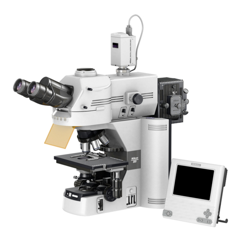
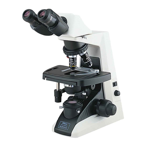
Nikon E800 User manual

Nikon
Microscope
ECLIPSE
E800
Instructions

I
Thank
you
for
purchasing
this
Nikon
product.
This
instruction
manual
is
written
for
users
of
the
Nikon
Microscope
ECLIPSE
E800.
To
ensure
corret
usage
read
this
manual
carefully
before
operating
the
instrument.
•
It
is
prohibited
to
alter
this
manual
in
part
or
whole
without
expressed
permission.
•
The
contents
of
this
manual
are
subject
to
change
without
any
notice.
•
Although
every
effort
has
been
made
to
ensure
the
accuracy
of
this
manual,
if
you
note
any
points
that
are
unclear
or
incorret,
contact
your
nearest
Nikon
representative.
•
Also
be
sure
to
read
the
instruction
manual
for
the
power
supply
that
you
are
using,
either
the
V-PS100DU,
or
the
V-PS100E.
Warning/Caution
Symbols
in
This
Manual
Though
Nikon
products
are
designed
to
provide
you
utmost
safety
during
use,
incorrect
usage
or
disregard
of
the
instructions
can
cause
personal
injury
or
property
damage.
For
your
safety,
read
the
instruction
manual
carefully
and
thoroughly
before
usage.
Do
not
discard
this
manual
but
keep
it
near
the
product
for
easy
reference.
Inside
this
instruction
manual,
safety
instructions
are
indicated
with
the
symbols
shown
be¬
low.
Be
sure
to
follow
the
instructions
marked
with
these
symbols
tor
your
safety.
Symbol
Disregarding
instructions
marked
with
this
symbol
may
lead
to
death
or
serious
injury.
Disregarding
instructions
marked
with
this
symbol
may
lead
to
injury
or
property
damage
.

CAUTION
1.
Check
the
light
source
The
power
supplies
V-PS
100DU
and
V-PS100E
provide
the
power
for
the
halogen
lamp
that
serves
as
the
microscope
light
source.
Although
these
power
supplies
can
power
a-halogen
lamp
of
up
to
12
V/
100
W,
the
specified
lamp
and
lamphouse
must
be
used.
The
equipment
could
be
damaged
if
a
non-
specified
combination
of
components
is
used.
Specified
lamphouse
:
Nikon
halogen
lamphouse
Model
C-LP
HALOGEN
12V100W
Specified
lamp
:
Halogen
lamp,
12
V-100
W
LONGLIFE
OSRAM
HLX
64623
or
PHILIPS
7724
2.
Turn
off
the
power
when
connecting
or
disconnecting
cables
or
when
replacing
the
lamp
In
order
to
prevent
electric
shock
and
damage
to
the
equipment,
always
turn
the
power
switch
on
the
power
supply
off
(flip
it
to
the
“
”
side)
and
unplug
the
power
cord
before
connecting
or
disconnecting
cables
or
replacing
the
lamp.
3.
Cautions
when
replacing
the
lamp
In
order
to
prevent
bums,
allow
the
lamp
to
cool
(for
at
least
thirty
minutes
after
turning
off
the
power)
before
replacing
the
lamp.
Furthermore,
in
order
to
prevent
electric
shock
and
damage
to
the
equipment,
always
turn
the
power
switch
on
the
power
supply
off
(flip
it
to
the
~
”
side)
and
unplug
the
power
cord
before
replacing
the
lamp.
After
replacing
the
lamp,
make
sure
that
the
lamphouse
cover
is
securely
closed.
Never
use
the
lamphouse
while
its
cover
is
open.
4.
Do
not
wet
If
the
microscope
or
the
power
supply
becomes
wet,
a
short
circuit
may
result
and
the
equipment
could
be
damaged
or
could
become
extremely
hot.
If
you
accidentally
spill
a
liquid
on
the
equipment,
immediately
turn
the
power
sw
itch
on
the
power
supply
off
(flip
it
to
the
“
”
side)
and
unplug
the
power
cord.
Then
use
a
dry'
cloth
to
wipe
away
the
moisture.
If
any
liquid
gets
inside
of
the
equipment,
do
not
attempt
to
use
it;
instead,
contact
your
nearest
Nikon
representative.
5.
Weak
electromagnetic
waves
This
microscope
emits
weak
electromagnetic
waves.
The
accuracy
of
any
precision
electronic
equipment
may
be
adversely
affected
if
positioned
near
this
microscope.
If
this
microscope
affects
TV
or
radio
reception,
move
the
radio
or
TV
away
from
the
microscope.
6.
Cautions
concerning
installation
Be
careful
not
to
pinch
your
hands
or
fingers
when
installing
the
microscope.
This
microscope
is
a
precision
optical
instrument,
and
using
or
storing
it
under
unsuitable
conditions
may
damage
it
or
may
have
an
adverse
affect
on
its
precision.
See
“Installation
Location"
on
P.27,
and
use
this
microscope
in
a
suitable
environment.
7.
Notes
on
transport
Because
this
microscope
is
a
precision
optical
device,
handle
it
carefully
and
do
not
subject
it
to
strong
physical
shocks.
(The
precision
of
the
objective
in
particular
may
be
adversely
affected
by
even
weak
physical
shocks.)
When
moving
the
microscope,
first
detach
the
lamphouse.
Then
have
at
least
two
people
carry
the
microscope,
at
least
one
on
each
side,
using
the
carrying
handles.
Be
sure
to
screw
the
carrying
handles
in
as
far
as
they
will
go
and
make
sure
that
they
are
secure.
If
the
carrying
handles
are
not
attached
securely,
they
could
come
out
or
break
while
the
microscope
is
being
carried,
creating
a
hazardous
situation.
Screw
the
carrying
hadles
into
the
upper
holes
on
the
rear
of
the
microscope.
If
you
use
the
lower
holes,
your
hands
will
be
caught
between
the
handles
and
the
table
when
you
place
the
microscope
down.
(P.27)
In
addition,
do
not
grasp
the
coarse
focus
knob,
the
fine
focus
knob,
the
eyepiece
tube,
the
stage,
etc.,
when
carrying
the
microscope;
there
is
a
chance
that
the
part
could
come
off,
and
the
equipment
could
be
damaged.

Names
of
Component
Parts

2.
Names
of
Operational
Parts

3.
Microscopic
Procedure
3
Set
the
brightness
adjuster
to
“9”.
a
This
brightness
provides
the
best
color
reproduc¬
tion.
(p.
23)
■■
Insert
filters
ND32
and
HUI
NCB11
into
the
optical
j|||l|
ND32:
Reduces
glare
in
Jlljl
the
binocular
eyepiece.
f||||
NCB11:
Improves
color
•iSra
reproduction,
(p.
21)
Lower
ND32
and
NCB11
Set
to
“9\
I
Move
the
lOx
objective
into
the
optical
path,
d
Rotate
the
revolving
^
nosepiece
until
the
lOx
3
objective
clicks
into
place.
Set
the
specimen
in
place
with
the
cover
glass
facing
Cover
glass
facing
up
la
\=r-
Select
lOx
9

i
;
3.
Microscopic
Procedure

3.
Microscopic
Procedure
Switch
to
any
desired
objective
and
view
the
specimen.
•
Re-adjust
the
focus.
•
Use
ND
filters
to
adjust
the
brightness.
•
Close
the
field
diaphragm
so
that
it
is
just
outside
the
field
of
view.
•
Close
the
condenser
aperture
diaphragm
to
about
70
to
80%
of
the
objective
numerical
aperture,
(p.
19)
■
If
a
portion
of
the
field
of
view
is
dark,
try
adjusting
the
condenser
centering
screws.
If
that
does
not
resolve
the
problem,
check
the
following
items:
•
Filter
insertion/removal
(p.
21)
•
Positioning
of
the
revolving
nosepiece
(p.
35)
•
Condenser
focusing
(p.
18)
•
Full
opening
of
the
field
and
aperturediaphragms
(p.
19,
20)
•
Optical
path
selection
for
the
eyepiece
tube
(p.
16)
•
Lamp
installation
(p.
28)
•
Revolving
nosepiece
installation
(p.
30)
•
Condenser
installation
(p.
30)
■
If
it
is
not
possible
to
focus
on
the
specimen,
check
the
following
items.
•
Mounting
of
the
specimen
(p.
35,
36)
•
Release
of
the
coarse
focus
stopper
(p.
15)
•
Thickness
of
the
cover
glass
(0.17
mm
is
standard)
(p.
35)

4.
Operation
of
Each
Part
Coarse
focus
stopper
The
coarse
focus
stopper
marks
the
stage
position
at
which
the
specimen
is
in
focus
by
restricting
the
movement
of
the
coarse
focus
knob.
(Movement
of
the
stage
by
the
fine
focus
knob
is
not
restricted.)
Once
the
coarse
focus
stopper
is
clamped
in
place,
the
coarse
focus
knob
cannot
be
used
to
move
the
stage
any
higher.
In
effect,
once
the
coarse
focus
knob
is
clamped
in
place
at
the
focus
position,
a
rough
focus
can
be
attained
the
next
time
simply
by
turning
the
coarse
focus
knob
as
far
as
it
will
go.
This
feature
is
convenient
when
viewing
similar
specimens
one
after
another.
If
the
coarse
focus
stopper
is
not
being
used,
the
coarse
focus
stopper
ring
should
be
loosened
as
far
as
it
will
go
(by
turning
it
as
far
as
it
will
go
in
the
direction
opposite
to
that
indicated
by
the
arrow
on
the
base
of
the
microscope.)
I
Using
the
coarse
focus
stopper
With
the
specimen
in
focus,
turn
the
coarse
focus
stopper
ring
as
far
as
it
will
go
in
the
direction
indicated
by
the
arrow
on
the
base
of
the
microscope
(about
270°).
The
coarse
focus
stopper
is
now
clamped
in
place.
When
changing
the
specimen,
lower
the
stage
by
turning
only
the
coarse
focus
knob.
After
changing
the
specimen,
gently
raise
the
stage
by
turning
only
the
coarse
focus
knob
as
far
as
it
will
go.
The
specimen
should
be
roughly
in
focus
when
the
stage
has
been
raised
as
far
as
it
will
go;
use
the
fine
focus
knob
to
bring
the
specimen
into
perfect
focus.

4.
Operation
of
Each
Part
Diopter
adjustment
method
1
Perform
steps
H
to
E
in
chapter
"3.
Microscopic
Procedure,”
so
that
the
specimen
is
fo¬
cused
with
the
lOx
objective.
2
Turn
the
diopter
adjustment
rings
on
the
eyepieces
and
align
the
edges
of
the
diopter
adjust¬
ment
rings
with
the
engraved
lines.
(This
is
the
diopter
adjustment
0
position.)
3
Move
the
40x
objective
into
the
optical
path.
Turn
the
coarse
and
fine
focus
knobs
to
focus
on
the
specimen.
4
Move
the
4x
or
the
lOx
objective
into
the
optical
path.
5
Turn
the
diopter
adjustment
rings
on
the
eyepieces,
not
the
coarse
and
fine
focus
knobs,
and
focus
on
the
specimen.
Do
so
while
peering
through
the
right
eyepiece
with
your
right
eye
and
the
left
eyepiece
with
your
left
eye.
6
Repeat
steps
3
to
5
twice.
I*]
Interpupillary
distance
adjustment
r--s
Before
adjusting
the
interpupillary
distance,
perform
steps
D
to
El
in
chapter
“3.
Microscopic
Pro-
:1
cedure”
so
that
the
specimen
is
focused
with
the
lOx
objective.
■
Adjust
the
interpupillary
distance
so
that
the
field
of
view
for
each
eye
is
aligned
on
one
position.
Doin°
so
will
make
observation
through
the
binocular
eyepiece
with
both
eyes
easier.
M
V'-M

4.
Operation
of
Each
Part
Condenser
aperture
diaphragm
The
aperture
diaphragm
is
important
because
it
is
related
to
the
resolution,
contrast,
depth
of
focus,
and
brightness
of
the
optical
image.
Turning
the
condenser
aperture
diaphragm
ring
changes
the
size
of
the
aperture
diaphragm.
As
the
aperture
diaphragm
is
stopped
down,
resolution
and
brightness
are
reduced
while
contrast
and
depth
of
focus
are
increased.
Conversely,
as
the
aperture
diaphragm
is
opened,
resolution
and
brightness
are
increased
while
contrast
and
depth
of
focus
are
reduced.
It
is
not
possible
to
adjust
one
pair
of
characteristics
without
affecting
the
other.
Generally,
a
satisfactory
image
with
appropriate
contrast
can
be
obtained
with
an
aperture
setting
that
is
70%
to
80%
of
the
objective
numerical
aperture.
If
the
aperture
diaphragm
is
stopped
down
too
far,
the
resolution
is
reduced;
therefore,
ex¬
cept
when
viewing
a
nearly
transparent
specimen,
we
do
not
recommend
stopping
down
the
aperture
to
less
than
60%
of
the
numerical
aperture
of
the
objective.
I
Adjusting
the
size
of
the
aperture
diaphragm
according
to
the
condenser
scale
Because
the
condenser
scale
indicates
the
numerical
aperture,
adjust
the
aperture
dia¬
phragm
ring
according
to
the
scale.
Normally,
the
index
on
the
aperture
diaphragm
ring
should
be
aligned
with
the
scale
line
corresponding
to
70%
to
80%
of
the
numerical
aperture
of
the
objective.)
Adjusting
the
size
of
the
aperture
diaphragm
by
using
a
centering
telescope
(sold
separately)
Remove
one
of
the
eyepieces
and,
using
a
special
adapter
(sold
separately),
mount
a
centering
telescope
in
its
place.
Turn
the
aperture
diaphragm
ring
to
stop
down
the
aper¬
ture
diaphragm
as
far
as
possible.
While
holding
down
the
milled
part
of
the
telescope,
turn
the
eyepiece
of
the
centering
telescope
and
focus
on
the
aperture
diaphragm
Turn
the
aperture
diaphragm
ring
to
adjust
the
size
of
the
aperture
diaphragm.
(Nor¬
mally,
the
aperture
diaphragm
should
be
adjusted
so
that
it
is
about
70%
to
80%
of
the
size
of
the
view’
field.)
Remove
the
centering
telescope
and
the
adapter,
and
then
re-install
the
eyepiece.

4.
Operation
of
Each
Part
Filters
In
this
microscope,
the
filters
indicated
below
are
housed
in
both
sides
of
the
base
of
the
microscope.
A
filter
is
inserted
into
the
optical
path
by
pressing
its
filter
insertion/removal
lever
down.
When
a
lever
is
lifted,
the
filter
is
removed
from
the
optical
path.
NCB11
(color
balancing
filter)
For
general
microscopy
and
color
photomicrography
Right
side
of
microscope
ND2
(transmission
rate:
50%)
For
brightness
adjustment
in
general
microscopy
and
photomicrography
Filter
cassette
on
left
side
of
micro¬
scope
ND8
(transmission
rate:
12.5%)
ND32
(transmission
rate:
3%)
GIF
(Green
interference
filter)
For
phase
contrast,
differential
interfer¬
ence
contrast,
and
contrast
adjustment
D
(lemon
skin)
Always
insert
in
optical
path
The
filters
in
the
filter
cassette
can
be
replaced
with
033
filters.
For
details
on
how
to
replace
the
filters,
refer
to
page
32.
Stage
Adjustment
of
torque
of
the
stage
motion
control
knobs
The
torque
of
the
X-axis
and
Y-axis
stage
motion
control
knobs
can
each
be
adjusted.
For
Y-axis
motion
To
tighen
the
tension
in
the
Y-
axis,
turn
Knob
B
in
the
direction
of
arrow
“a"
while
holding
Knob
A;
to
reduce
the
tension,
turn
Knob
B
in
the
opposite
direction.
For
X-axis
motion
To
tighten
the
tension
in
the
X-axis,
turn
Knob
C
in
the
direction
of
arrow
“b”
while
holding
Knob
D;
to
reduce
the
tension,
turn
Knob
C
in
the
opposite
direction.
a
b
TOSr
^
gums—
Knob
A
Knob
B
Knob
C
Knob
D

Preset
voltage
switch
(for
photomicrography)
The
color
temperature
of
the
lamp
varies
according
to
the
voltage.
If
the
voltage
is
high,
the
color
temperature
of
the
lamp
increases
and
the
light
becomes
bluer;
if
the
voltage
is
low,
the
color
tem¬
perature
of
the
lamp
decreases
and
the
light
becomes
redder.
Therefore,
in
order
to
obtain
the
best
color
reproduction
in
color
photomicrography,
it
is
necessary
for
the
lamp
voltage
to
be
kept
con¬
stant.
When
using
daylight-type
color
film,
the
standard
setup
is
to
use
the
color
balancing
filter
(NCB
11)
and
set
the
lamp
voltage
to
9
V.
The
preset
voltage
switch
is
used
to
automatically
set
the
standard
lamp
voltage
(9
V).
Because
the
brightness
adjuster
also
serves
as
the
preset
voltage
switch,
setting
the
brightness
adjuster
to
the
“PRESET’
1
position
automatically
sets
the
lamp
voltage
to
9
V.
Fine
adjustment
of
the
preset
voltage
If
the
final
images
on
color
film
shot
with
the
brightness
adjuster
set
to
the
“PRESET"
position
are
reddish
or
bluish,
adjust
the
preset
voltage.
Fine
adjustments
of
up
to
±
1
V
can
be
made
to
the
9
V
setting
by
using
a
minus
(-)
screwdriver
to
turn
the
rotary
switch
(the
preset
voltage
fine
adjustment
dial)
on
the
left
side
of
the
microscope
base.
When
images
are
reddish:
Increase
the
voltage.
(Doing
so
will
increase
the
lamp
color
tem¬
perature,
giving
the
light
a
bluish
tint.)
When
images
are
bluish:
Decrease
the
voltage.
(Doing
so
will
decrease
the
lamp
color
tem¬
perature,
giving
the
light
a
reddish
tint.)
If
this
adjustment
is
not
enough
to
resolve
the
problem,
also
use
color
compensation
filters
(CC
filters),
available
on
the
market.
R1
Oil-immersion
operation
■
■
(using
an
oil-immersion
type
objective
and
condenser)
23

Assembly
«/i
•Tv.
,
•
.VJ
1:1
J;;
,i
>|
-tk.
-
,,-j
•
■
•==*
•
-i
WARNING
In
order
to
prevent
electric
shock
and
fire,
turn
the
power
switch
on
the
power
supply
off
(flip
to
the
“
”
side)
during
assembly.
Also
turn
the
microscope’s
sub¬
power
switch
off.
CAUTION
•
When
moving
the
microscope,
first
detach
the
lamphouse.
Then
have
at
least
two
people
carry
the
microscope,
at
least
one
on
each
side,
using
the
carrying
handles.
•
Be
sure
to
screw
the
carrying
handles
in
as
far
as
they
will
go
and
make
sure
that
they
are
secure.
If
the
carrying
handles
are
not
attached
securely,
they
could
come
out
or
break
while
the
microscope
is
being
carried,
creating
a
hazardous
situation.
Screw
the
carrying
handles
into
the
upper
holes
on
the
rear
of
the
microscope.
If
you
use
the
lower
holes,
your
hands
will
be
caught
between
the
handles
and
the
table
when
you
set
the
microscope
down.
•
Do
not
grasp
the
coarse
focus
knob,
the
fine
foe
stage,
etc.,
when
carrying
the
microscope;
there
is
a
chance
that
the
part
could
come
off,
and
the
equipment
could
be
damaged.
•
Be
careful
not
to
pinch
your
hands
or
fingers
when
setting
up
the
microscope.
I
Tools
needed
•
Two
hexagonal
screwdrivers
(provided)
•
One
hexagonal
wrench
(provided)
•
Four
carrying
handles
(provided)
•
One
coin
(or
a
minus
(-)
screwdriver)
Assemble
each
part
in
sequence
as
numbered
in
the
diagram.
(For
details,
refer
to
pages
27
to
33.)
Viewing
will
be
adversely
affected
if
any
of
the
lenses
are
scratched
or
if
they
have
any
fingerprints
on
them.
Handle
the
lenses
carefully
during
assembly.
Because
this
microscope
is
a
precision
optical
device,
handle
it
carefully
and
do
not
subject
it
to
strong
physical
shocks.
(The
precision
of
the
objectives
in
particular
may
be
adversely
affected
by
even
weak
physical
shocks.)
25

5.
Assembly
1.
Setting
Up
the
Microscope
Q^ypiQjsj
•
When
moving
the
microscope,
have
at
least
two
people
carry
the
microscope,
at
f
least
one
on
each
side,
using
the
carrying
handles.
•
Be
sure
to
screw
the
carrying
handles
in
as
far
as
they
will
go
and
make
sure
that
they
are
secure.
If
the
carrying
handles
are
not
attached
securely,
they
could
come
out
or
break
while
the
microscope
is
being
carried,
creating
a
hazardous
situation.
Screw
the
carrying
handles
into
the
upper
holes
on
the
rear
of
the
mi¬
croscope.
If
you
use
the
lower
holes,
your
hands
will
be
caught
between
the
handles
and
the
table
when
you
set
the
microscope
down.
•
In
addition,
when
transporting
the
assembled
microscope,
do
not
grasp
the
coarse
focus
knob,
the
fine
focus
knob,
the
eyepiece
tube,
the
stage,
etc.,
when
carrying
the
microscope;
there
is
a
chance
that
the
part
could
come
off,
and
the
equipment
could
be
damaged.
•
Be
careful
not
to
pinch
your
hands
or
fingers
when
installing
the
microscope.
Installation
location
This
product
is
a
precision
optical
instrument,
and
using
or
storing
it
under
unsuitable
conditions
may
damage
it
or
may
have
an
adverse
effect
on
its
precision.
The
following
conditions
should
be
kept
in
mind
when
selecting
the
installation
location:
•
Avoid
installing
the
microscope
in
a
bright
location,
such
as
in
a
room
that
receives
direct
sunlight,
or
directly
under
room
lights.
The
quality
of
the
view
through
the
microscope
dete¬
riorates
if
there
is
a
lot
of
ambient
light.
•
Install
the
microscope
in
a
location
that
is
free
from
dust
or
dirt.
•
Install
the
microscope
on
a
flat
surface
with
little
vibration.
•
Install
the
microscope
on
a
sturdy
desk
or
table
that
is
able
to
bear
the
weight
of
the
micro¬
scope.
•
Install
the
microscope
in
a
location
where
the
temperature
will
range
from
0
to
40°C
and
where
the
humidity
is
less
than
85%.
If
the
microscope
is
installed
in
a
warm,
humid
location,
condensation
or
mold
may
form
on
the
lenses,
degrading
performance
or
damage
the
equipment.
Screw
the
carrying
handles
into
the
holes
on
both
sides
of
the
front
and
rear
(use
the
upper
holes)
of
the
microscope.
Be
sure
to
screw
all
of
the
handles
in
as
far
as
they
will
go.
Have
at
least
two
people,
with
at
least
one
on
both
sides,
carry
the
microscope
to
the
location
where
it
is
to
be
installed.
After
placing
the
microscope
in
the
desired
position,
use
a
coin
(or
minus
(-)
screwdriver)
to
remove
the
decorative
screws
on
the
rear
of
the
microscope
(in
the
lower
holes).
Remove
the
front
pair
of
carrying
handles
from
the
microscope
and
screw
them
into
the
lower
holes
on
the
rear
of
the
microscope.
Screw
the
decorative
screws
into
the
open
holes
on
the
front
of
the
27

5.
Assembly
1
Confirm
that
the
power
supply
power
switch
is
off
(i.e.,
that
it
is
flipped
to
the
“
'
”
side).
Also
confirm
that
the
sub-power
switch
on
the
microscope
is
in
the
OFF
position.
2
If
the
lamphouse
is
mounted
on
the
microscope,
use
a
hexagonal
screwdriver
to
loosen
the
lamphouse
clamp
screw
(The
screw
is
on
the
top
of
the
lamphouse
mount)
and
then
remove
the
lamphouse
from
the
microscope.
3
Use
a
hexagonal
screwdriver
to
loosen
the
clamp
screw
on
the
front
of
the
lamphouse
and
remove
the
cover.
4
While
pressing
the
lamp
clamp
lever,
push
the
lamp
into
the
socket
pin
holes
as
far
as
it
will
go.
(Do
not
touch
the
glass
portion
of
the
lamp
with
your
bare
hands.)
5
Return
the
clamp
lever
to
its
original
position.
Make
sure
that
the
lamp
is
not
crooked.
6
Close
the
cover
securely
and
tighten
the
clamp
screw.Make
sure
that
the
cover
is
fixed
in
place
and
will
not
come
off
even
when
shook
by
hand.
7
Plug
the
lamphouse
into
the
microscope
so
that
the
lamphouse
plug
fits
into
the
lamphouse
socket.
Tighten
the
lamphouse
clamp
screw
to
secure
the
lamphouse
in
place.
■
4.
Stage
Installation
Place
the
stage
with
the
bottom
facing
up.
Place
the
substage
on
top
of
the
stage.
Align
the
three
mounting
holes
on
the
stage
and
the
substage,
and
then
use
a
hexagonal
screwdriver
to
tighten
the
three
mounting
bolts
so
that
the
stage
is
securely
attached
to
the
substage.
29

5.
Assembly
Objective
Installation
Lower
the
stage
completely.
Screw
the
objectives
into
the
revolving
nosepiece
so
that
the
magnification
increases
when
the
re¬
volving
nosepiece
is
rotated
in
the
clockwise
direction,
when
looking
down
on
the
revolving
nose-
piece
from
above.
I
Note
on
removing
objectives
If
there
is
a
specimen
on
the
stage,
remove
it
first.
Lower
the
stage
completely,
and
hold
each
objective
in
both
hands
so
that
it
does
not
fall
when
you
remove
it.
|
10.
Standard
Module
Installation
\
Install
the
standard
module
by
aligning
the
two
pins
on
the
standard
module
with
the
holes
on
the
i
microscope,
and
then
use
the
hexagonal
wrench
to
tighten
the
four
bolts
with
hexagonal
holes
so
•••--!
that
the
standard
module
is
secured
in
place.
|
11.
Triocular
Eyepiece
Tube
Installation
\
Use
a
hexagonal
screwdriver
to
loosen
the
eyepiece
tube
clamp
screw.
Tilt
and
insert
the
round
:
dovetail
on
the
triocular
eyepiece
tube
to
the
round
dovetail
mount
on
the
standard
module.
Then
1
tighten
the
eyepiece
tube
clamp
screw
so
that
the
triocular
eyepiece
tube
is
secured
in
place.

5.
Assembly
Power
Supply
Connection
There
are
three
types
of
cables
that
need
to
be
connected:
the
lamp
output
cable*
the
lamp
voltage
Lamp
output
cable:
Plug
one
end
into
the
POWER
connector
on
the
rear
of
the
microscope,
and
the
other
end
into
the
LAMP
OUT
connector
on
the
rear
of
the
power
supply,
and
then
screw
on
the
locking
rings
so
that
each
connection
is
secure.
Lamp
voltage
control
cable:
Plug
one
end
into
the
CONTROL
connector
on
the
rear
of
the
microscope,
and
the
other
end
into
the
CONTROL
connector
on
the
rear
of
the
power
supply.
Power
cord:
Plug
the
socket
onto
the
AC
input
connector
on
the
rear
of
the
power
supply,
and
insert
the
plug
into
an
AC
outlet.
■
16.
Installation
of
Photomicrographic
Equipment
(Sold
Separately)
For
details
on
how
to
assemble
the
photomicrographic
equipment
and
on
how
to
take
photo¬
micrographs.
refer
to
the
instruction
manual
provided
with
the
photomicrographic
equipment.
Remove
the
cap
from
the
vertical
tube
on
the
triocular
eyepiece
tube,
and
attach
a
photo
tube.
Drop
a
PL
projection
lens
inside
the
photo
tube
(sold
separately).
Confirm
that
the
projection
lens
is
in
as
far
as
it
will
go.
t
Insert
the
main
body
of
the
photomicrographic
equipment
on
to
the
photo
tube
as
far
as
it
will
go.
With
the
finder
mount
facing
the
front,
secure
the
main
body
in
place
with
the
photographic
equip¬
ment
clamp
screws.
(If
the
photo
tube
on
the
photographic
equipment
has
a
groove
around
its
cir¬
cumference.
secure
the
equipment
in
place
with
two
small
clamp
screws.
If
there
is
no
groove
around
the
circumference
of
the
photo
tube,
secure
it
in
place
with
one
clamp
screw.)
Refer
to
the
instruction
manual
provided
with
the
photomicrographic
equipment
for
details
on
how
to
mount
a
finder,
camera
box,
etc.
H17.
Storing
the
Tools
H
When
you
finish
using
the
hexagonal
screwdriver
and
the
hexagonal
wrench,
insert
them
into
the
tool
storage
compartment
on
the
base
of
the
microscope.
Assembly
is
now
complete.
33

6.
Troubleshooting
Tables
Problem
Cause
Countermeasures
Viewing
is
poor
(too
much
or
too
little
contrast,
poor
resolution)
(The
details
cannot
be
viewed
clearly)
The
cover
glass
is
too
thick.
Use
the
specified
type
of
cover
glass
(thickness:
0.17
mm).
There
is
no
cover
glass.
There
is
no
oil
on
the
tip
of
an
oil-immersion
type
objective.
Apply
Nikon
immersion
oil.
(p.
23)
The
specified
immersion
oil
is
not
being
used.
There
are
bubbles
in
the
immersion
oil.
Remove
the
bubbles.
(p.
24)
There
is
immersion
oil
on
the
tip
of
a
dry-
type
objective.
(Especially
in
the
case
of
a
40x
objective)
Clean
the
objective.
(p.
24)
The
compensation
ring
on
an
objective
with
a
compensation
ring
has
not
been
adjusted.
Adjust
the
compensation
ring
according
to
the
cover
glass.
There
is
dirt
or
dust
on
the
lens,
condenser,
objective
or
specimen.
Clean
the
components.
(p.
38)
Uneven
focus
The
revolving
nosepiece
has
not
been
installed
properly.
Install
the
revolving
nosepiece
properly.
(p.
30)
The
revolving
nosepiece
has
not
been
rotated
until
it
has
clicked
into
place.
Turn
the
revolving
nosepiece
until
it
dicks
into
place.
(p.
9)
The
specimen
is
not
secured
in
place
on
the
stage.
Install
the
specimen
properly
on
the
specimen
holder
on
the
stage.
The
stage
has
been
installed
on
a
slant.
Install
the
stage
correctly.
(p.
29)
Image
flows
The
revolving
nosepiece
has
not
been
installed
properly.
Install
the
revolving
nosepiece
properly.
(p.
30)
The
revolving
nosepiece
has
not
been
rotated
until
it
has
clicked
into
place.
Turn
the
revolving
nosepiece
until
it
clicks
into
place.
(P-
9)
The
specimen
is
not
secured
in
place
on
the
stage.
Install
the
specimen
properly
on
the
specimen
holder
on
the
stage.
The
condenser
is
not
centered.
Center
the
condenser.
(p.
18)
The
stage
has
been
installed
on
a
slant.
Install
the
stage
correctly.
(p.
29)
Image
is
yellowish
An
NCB1
1
filter
is
not
being
used.
Use
the
NCB
11
filter.
(p.
21)
The
lamp
voltage
is
too
low.
Set
the
brightness
adjuster
to
“PRESET'
or
to
position
“9”,
and
then
adjust
the
brightness
through
the
ND
filter
combination.
(p.
23)

6.
Troubleshooting
Tables
Electrical
system
The
lamp
does
not
fight
when
the
power
is
turned
on
Cause
Countermeasure
The
power
supply
is
not
plugged
in.
Plug
the
power
cord
into
an
outlet.
(p.
32)
The
cables
between
the
microscope
and
the
power
supply
are
not
connected.
Connect
the
cables.
(p.
32)
The
sub-power
switch
is
set
to
“EPI.”
Set
the
switch
to
“DIA.”
(p.
8)
The
lamp
has
not
been
installed.
Install
the
lamp.
(p.
29)
The
lamp
is
burned
out.
Replace
the
lamp.
(p.
29)
The
specified
lamp
is
not
being
used.
Use
the
specified
lamp.
(Refer
to
the
electrical
standards
on
P.39.)
(p.
28)
The
specified
lamp
is
not
being
used.
Use
the
specified
lamp.
(Refer
to
the
electrical
standards
on
P.39.)
(p.
28)
The
lamp
voltage
control
cable
has
not
been
connected.
Connect
the
cable.
(p.
33)
The
lamp
is
near
the
end
of
its
life.
Replace
the
lamp.
(p.
29)
Inadequate
brightness
no
effect.
The
lamp
flickers;
the
brightness
The
connectors
are
not
connected
securely,
is
unstable
—-
The
lamp
is
not
plugged
into
its
socket
securely.
Secure
the
connections.
Insert
the
lamp
securely
into
its
socket.
37
Other manuals for E800
2
Table of contents
Other Nikon Microscope manuals

Nikon
Nikon S-kt User manual

Nikon
Nikon SMZ-U Manual

Nikon
Nikon Eclipse TE300 User manual

Nikon
Nikon SMZ460 User manual

Nikon
Nikon Eclipse E400 POL User manual
Nikon
Nikon Eclipse LV100DA-U User manual

Nikon
Nikon E800 User manual

Nikon
Nikon Eclipse TE200 User manual

Nikon
Nikon ECLIPSE MA200 User manual

Nikon
Nikon T1-FM User manual

Nikon
Nikon Alphapot2 Manual
Nikon
Nikon Eclipse L200 User manual

Nikon
Nikon SMZ-1B User manual

Nikon
Nikon Eclipse E600 User manual

Nikon
Nikon SMZ745T User manual

Nikon
Nikon Eclipse L200A User manual

Nikon
Nikon ECLIPSE TE2000-E User manual

Nikon
Nikon P-400R User manual

Nikon
Nikon A1+ Manual

Nikon
Nikon Eclipse E600 User manual