Ninka Qanto R4 User manual
US
CA
Qanto R4
Qanto_Id_A4_00000.50.65053_US
1x(2x)
Bottom tray (middle tray: OPTIONAL)
Estante inferior (estante central: OPCIONAL)
Tablette inférieure (tablette du milieu : EN OPTION)
Assembly instruction
Instrucciones de montaje
Instructions de montage
READ THIS MANUAL BEFORE ASSEMBLING OR USING
THIS PRODUCT. Failure to follow the instructions and safety
precautions in this manual can result in serious injury.
Keep this manual in a safe location for future reference.
English 2
Espanõl 24
Français 46
Toute reproduction, même d’extraits, n’est autorisée qu’avec l’autorisation écrite de Ninkaplast GmbH.
Ninguna parte de este manual puede ser reproducida sin el consentimiento escrito de Ninkaplast GmbH.
Reproduction, even in excerpts, is permitted only with the written permission of Ninkaplast GmbH.
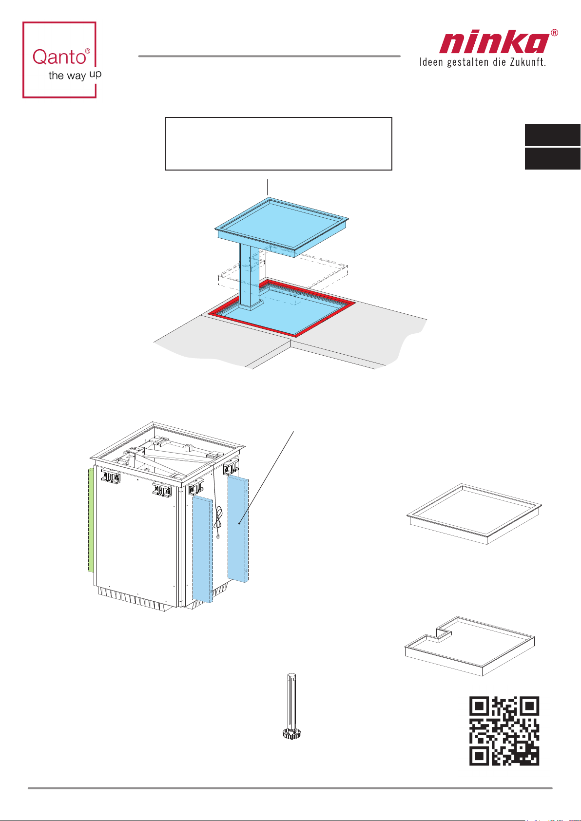
Scope of supply
Volumen de suministro
Étendue de la livraison
4x
Spacer bars: OPTIONAL in scope of supply
Barras distanciadoras: OPCIONAL en el volumen de suministro
Entretoises : EN OPTION dans l’étendue de la livraison
1x
Cabinet with lifting system
Armario con sistema de elevación
Armoire avec système de levage
5x
Adjustable feet
Patas ajustables
Pied ajustable
1x
Top tray
Estante superior
Tablette supérieure

2Qanto_Id_A4_00000.50.65053_US
General assembly instructions
•Anyone who performs connection or assembly work on Qanto must
have access to these assembly instructions. Follow these instructions.
Non-observance of the above mentioned instructions can lead to acci -
dents resulting in severe personal injury, such as trapped fingers and
electric shock.
•Assembly may be performed by expert personnel only, as incorrect
assembly may lead to injury or electric shock.
clearance from the edge of the counter, otherwise there is a risk of
injury.
• If the product is visibly damaged, it must not be installed, as a possible
malfunction may lead to injury or electric shock.
for the movement of the lifting system. When Qanto is extended upward
and to both sides, a clearance of about 7,87“ (200 mm) to other cabinets
or shelving must be observed, otherwise there is a risk of injury.
•A clearance of 11,82“ (300 mm) must be observed between Qanto and a
gas stove, as heat may cause damage to the unit.
•The electrical system of Qanto must be accessible (e.g., a double so-
cket under the cabinet near the base).
• Make sure the cables are undamaged, as this may lead to electrical shock.
• Before connecting the electrical drive to the in-house power mains,
on the type plate. The mains voltage and permissible input voltage must
be identical. If not, Qanto must not be connected.
• If the control unit causes unusual noises or odours during operation,
•
interrupt the power supply.
Select the length of the fastening screws for the bars in such a way that
they do not poke through the cabinet, otherwise the unit will be damaged
and this may lead to injury.
WARNING
!
CAUTION
!
NOTICE
EN

290
280
270
= S
260
250
240
230
220
H- 27,95“ = X
X● 25,4 = S
H
3
Step 1:
Measure/determine the height Hfrom the floor
to the top of the counter.
Step 2:
Deduct - 27.95" from the height H. You will obtain
the value X. Multiply this value by 25.4 to obtain
the value S.
Step 3:
Shorten the adjustable feet at value Son the
adjustable foot.
Counter
Floor
Adjustable foot
Qanto_Id_A4_00000.50.65053_US
1.
2.
3.
EN
Cutting tools and saws must be used with
caution to avoid injury.
WARNING
!

4
Step 4:
Lay the cabinet on a scratch guard foundation
and mount the adjustable feet carefully using a
rubber hammer on the cabinet base
Measure the thickness AP of the worktop.
Step 5:
Scratch guard
Qanto_Id_A4_00000.50.065050_US
AP
4.
5.
EN

5
8.
7.
AP
AP
Qanto_Id_A4_00000.50.065050_US
Step 6:
Screw the support part to the wooden
carcase.
Step 7:
Loosen the screws (8X)
Step 8:
Remove the aluminium frame
from the carcase.
6.
EN
6Qanto_Id_A4_00000.50.065050_US
EN
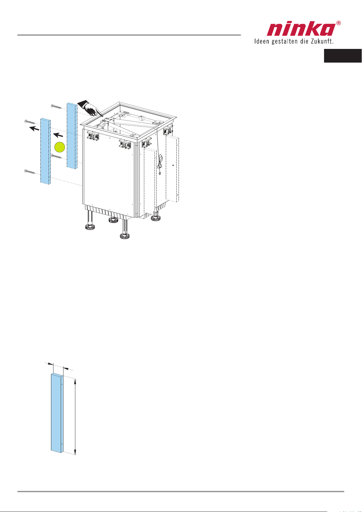
Step 9:
If spacer bars are included in the scope of supply
remove the bars only from the rear side of the
cabinet
Rear side of cabinet
Spacer bar
9.
Step 10:
If no spacer bars are included in the scope of supply, you must create them
yourself. The width Ais calculated from the planning dimensions P- 22.36".
The maximum length of the bars amounts to 22.44".
max. 22,44“
4x
Spacer bars
A

7
Qanto_Id_A4_00000.50.065050_US
Step 11:
How is the installation position of Qanto planned?
min. min. min.
min. min. min.
min.
23,62“ 23,62“ 23,62“ 23,62“
min.
25,59“ 25,59“ 25,59“ 25,59“
Lifting column Lifting column Lifting column Lifting column
Lifting column Lifting column
L1 L2
L3 L4
R2 R1
R4 R3
min.
23,62“
min.
23,62“min.
23,62“
min. min. min.
25,59“ 25,59“ 25,59“
min.
23,62“
min.
25,59“
Lifting column Lifting column
EN

B=P1 - 23,34
"
1,69
"
1,69
21,65
"
21,65
"
A =P2 - 23,34
"
AB
P1
P2
8
min. 25,59"
min. 23,62"
Qanto_Id_A4_00000.50.065050_US
Step 12:
Determine the installation situation; a variety of options is available. 8 options have been
illustrated as examples (see L1-L4 and R1-R4)
P2
= planning dimension
P1
= planning dimension
Step 13:
If no spacer bars are included in the scope of supply, you must create them yourself.
The width
A
is calculated from the planning dimensions
P2
- 23.34".
The width
B
is calculated from the planning dimensions
P1
- 23.34".
The maximum length of the bars amounts to 22.44".
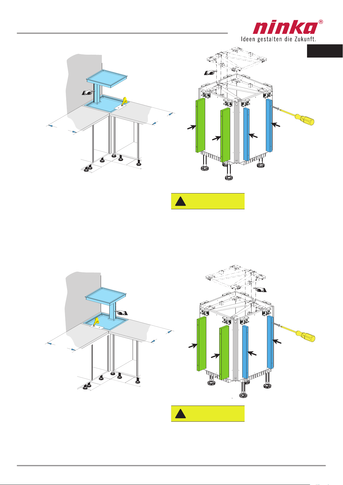
Step 14:
In case of a Qanto installation position of L1-L4 or R1-R4, you must mount the spacer bars
as shown in the figure opposite. Pay attention to the position of the lifting column! Select the
length of the fastening screws for the bars in such a way that they do not poke through the
cabinet!
EN
9
min.
23,62"
min.
25,59"
min.
23,62"
min.
25,59"
L1
L2
Qanto_Id_A4_00000.50.065050_US
Select the length of the fastening screws for the
bars in such a way that they do not poke through
the cabinet, as this will damage the unit and may
lead to injury.
CAUTION
!
Select the length of the fastening screws for the
bars in such a way that they do not poke through
the cabinet, as this will damage the unit and may
lead to injury.
CAUTION
!
EN

B =P1 - 23,34"1,69"
1,69"
21,65"
21,65"A=P2 - 23,34"
B
A
P1
P2
10
min. 25,59"
min. 23,62"
L3
L4
Qanto_Id_A4_00000.50.065050_US
min.
23,62"
min.
23,62"
min.
25,59"
min.
25,59"
Select the length of the fastening screws for the bars
in such a way that they do not poke through the cabi-
net, as this will damage the unit and may lead to injury.
CAUTION
!
Select the length of the fastening screws for the bars
in such a way that they do not poke through the cabi-
net, as this will damage the unit and may lead to injury.
CAUTION
!
EN

A=P1 - 23,34" 1,69"
1,69"
21,65"
21,65"B =P2 - 23,34"
P1
P2
B
A
11
min. 25,59"
min. 23,62"
R1
R2
Qanto_Id_A4_00000.50.065050_US
min.
23,62"
min.
23,62"
min.
25,59"
25,59"
min.
Select the length of the fastening screws for the bars
in such a way that they do not poke through the cabi-
net, as this will damage the unit and may lead to injury.
CAUTION
!
Select the length of the fastening screws for the bars
in such a way that they do not poke through the cabi-
net, as this will damage the unit and may lead to injury.
CAUTION
!
EN

A =P1 - 23,34" 1,69"
1,69"
21,65"
21,65"B=P2 - 23,34"
P1
P2
A
B
12
min. 23,62"
min. 25,59"
R3
R4
Qanto_Id_A4_00000.50.065050_US
min.
23,62"
min.
23,62"
min.
25,59"
min.
25,59"
Select the length of the fastening screws for the bars
in such a way that they do not poke through the cabi-
net, as this will damage the unit and may lead to injury.
CAUTION
!
Select the length of the fastening screws for the bars
in such a way that they do not poke through the cabi-
net, as this will damage the unit and may lead to injury.
CAUTION
!
EN

13
18.
17. 17.
1,69
1,69
15.
16.
16.
Qanto_Id_A4_00000.50.065050_US
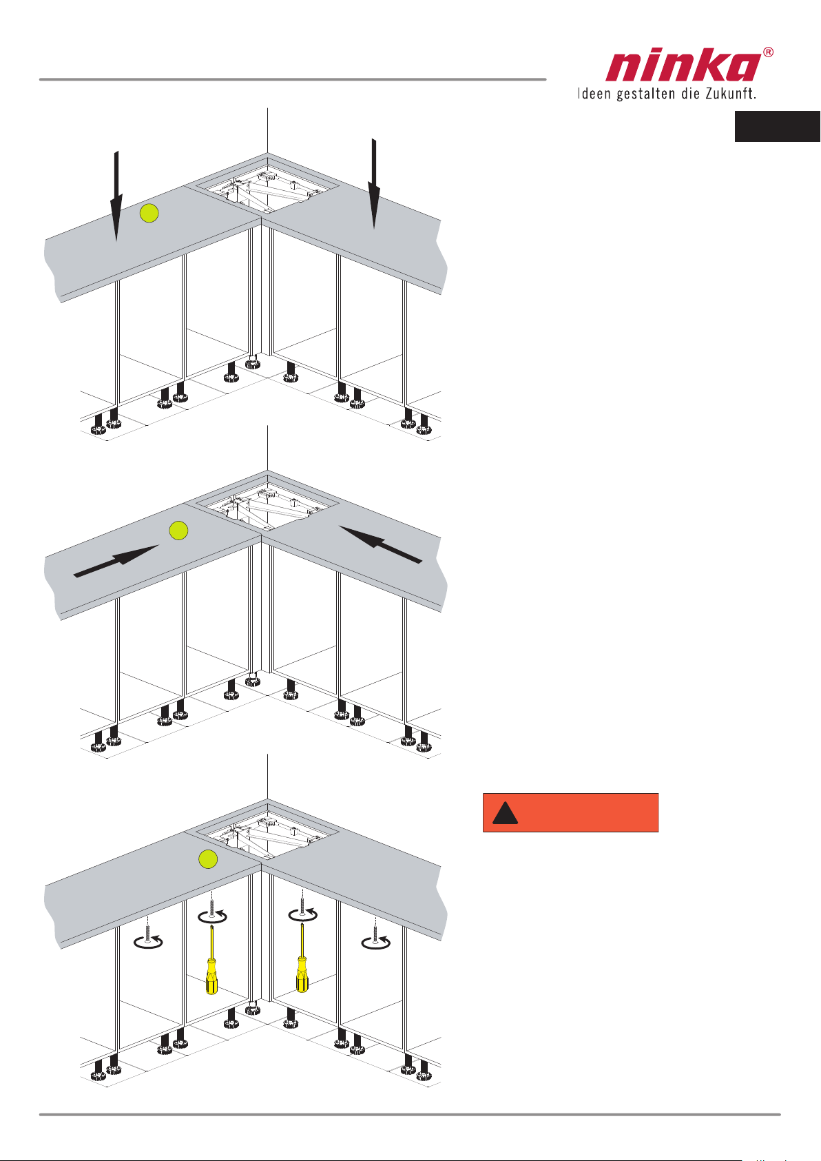
Step 15:
Remove the connecting cable and plug from the
cabinet base of Qanto.
Step 16:
Place the cabinet in the corner at a distance of
1,69" (43 mm) from the walls.
Step 17:
Place the accompany cabinet next to Qanto.
Step 18:
Align the accompanying cabinet.
EN
WARNING
!
Make sure the cables are undamaged as this
may lead to electrical shock.

14
sngisedsuoiraV
19.
20.
22.
21.
Corner strip NOT in scope of supply
Qanto_Id_A4_00000.50.065050_US
Step 19:
Drill the holes for fixing the cornice
Step 20:
Screw the accompanying cabinets only to the
corner bar. Do NOT screw it to the corner cabinet.
Step 21:
Drill the holes to attach the accompanying
cabinets to the corner cabinet.
Step 22:
Screw the accompanying cabinets to the
corner cabinet. Do NOT screw it to the
corner cabinet.
Select the length of the fastening screws
for the bars in such a way that they do not
poke through the cabinet, as this will
damage the unit and may lead to injury.
CAUTION
!
EN
WARNING
!
The corner bar is not included in the scope
of supply. Create this bar. The dimensions
depend on the planning dimensions. The
corner bar can have different designs.

23.
23.
15
1,89"
2,76"
1,89"
0,55"
R0,39"
21,26"
21,26"
min. 25,59"min.
min. 23,62"
Cut-out for button
Cut-out for button
Step 24:
Create the cut-out in the counter
according to the drawing
Saw the cutout shown in the
countertop
Qanto_Id_A4_00000.50.065050_US
Step 23:
Lay the counters loosely on the cabinets.
Do not yet attach them!
24.
Cutting tools and saws must be used
with caution to avoid injury.
WARNING
!
EN
16 Qanto_Id_A4_00000.50.065050_US
Step 27:
Screw the counters to the accompanying
cabinets.The screws are NOT included in
the scope of supply. Pay attention to the
correct screw length! The screws must
not protrude through the counters or
damage their surface..
Step 26:
Connect the counters
Step 25:
Place the counters on the cabinets
EN
27.
26.
25.
The screws must not protrude through the
counter/worktop as this will damage the
surface and may lead to injury. Ensure
that the cable is not damaged or squee-
zed as this may lead to electric shock.
WARNING
!
30.
29.
28.
17
28.
Qanto_Id_A4_00000.50.065050_US
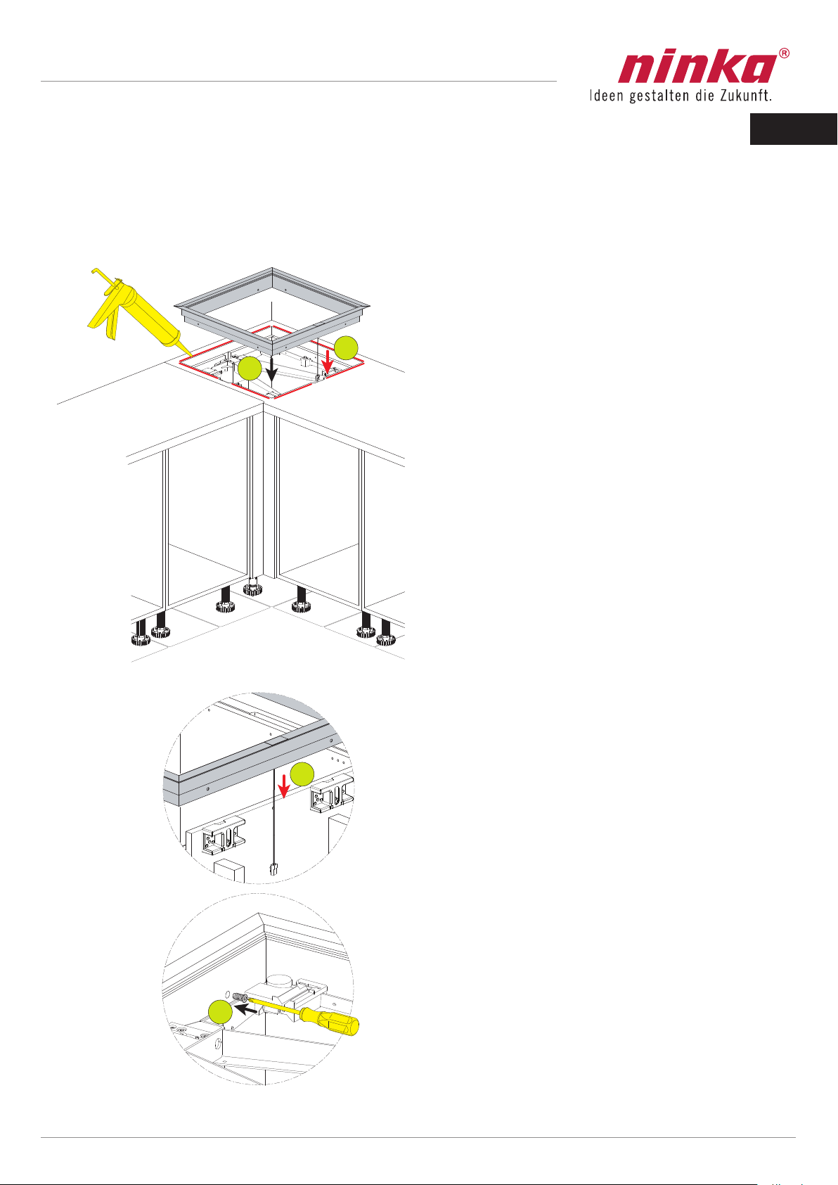
OPTIONAL You can seal off the counters toward the masking frame
Step 28:
Conduct the plug from the switch downward
along the side of the cabinet
Step 29:
Insert the frame (optional: with silicone
sealing)
Step 30:
Screw in screws (8X)
EN

18 Qanto_Id_A4_00000.50.065050_US
Step 31:
Insert the plug of the control into the socket
under the cabinet base.
Step 32:
Connect the corner cabinet to the power mains,
e.g., with a double socket. The connection must
be accessible.
31.
31.
32.
EN
Ensure that the cable is not damaged or squee-
zed as this may lead to electric shock.
WARNING
!
33.
33.
34.
34.
19
Qanto_Id_A4_00000.50.065050_US
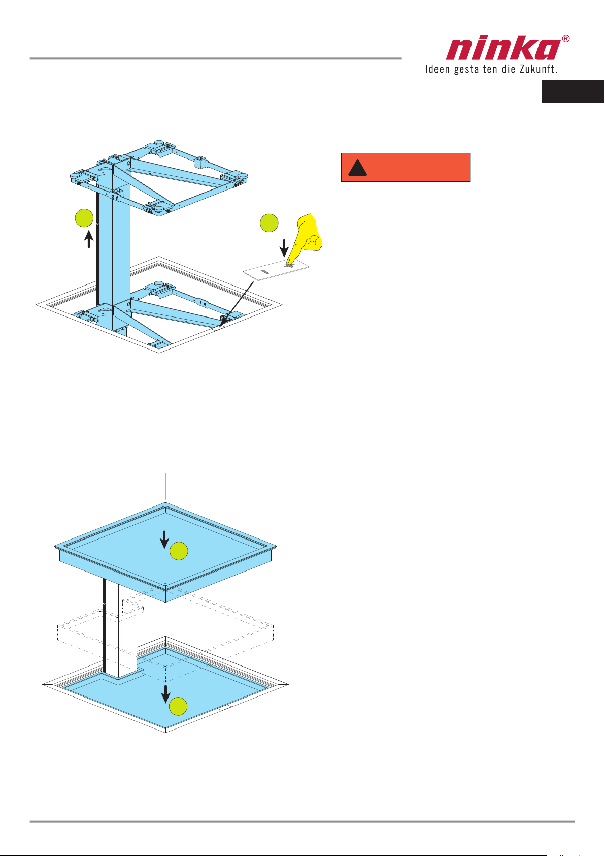
Step 33:
Move the lifting frame all the way up by
pressing and holding the +button on the
control.
Step 34:
Lay the trays on the lifting frame.
Lifting frame
Top tray
Bottom tray
EN
During installation and normal operation,
sufficient space should be provided for
the movement system to operate, other-
wise injury may occur.
WARNING
!
H = H
35.
35.
36.
37.
20 Qanto_Id_A4_00000.50.065050_US
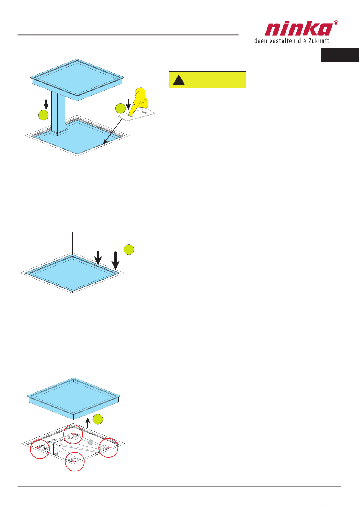
Step 35:
Move the lifting frame all the way down by pressing
and holding the -button on the control.
Step 36:
Check the height of the tray in relation to the height
of the masking frame of the corner cabinet.
Tray
Masking frame
Step 37:
Lift the tray from the tray carrier.
EN
If the maximum weight capacity is exceeded and a
body part impedes the mov ment between a tray
and the frame, then injury can occur.
CAUTION
!
Table of contents
Languages:
Other Ninka Kitchen Appliance manuals


