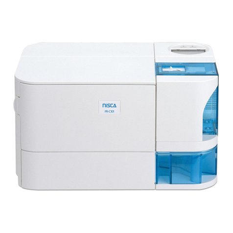
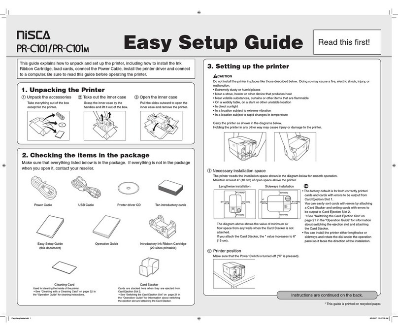
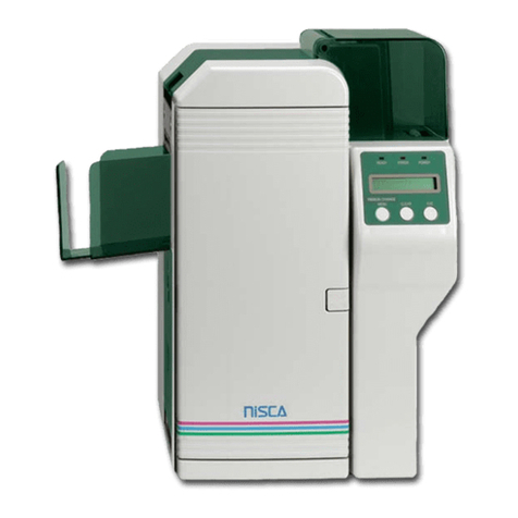
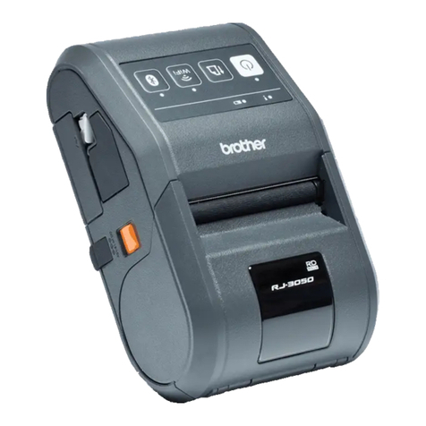
Nisca PR-C101M User manual

Service Manual
Ver. 1.0
Apr./2008

CONTENTS
1. Over view of the Device
?Over view of the Device ・・・・・・・・・・・・・・・・・・・・・・・・・・・・・・・・・・ 1
『Basic Specification 』・・・・・・・・・・・・・・・・・・・・・・・・・・・・・・ 1
? Description of Mechanism ・・・・・・・・・・・・・・・・・・・・・・・・・・・・・・・・・ 1
? Description of electric functions ・・・・・・・・・・・・・・・・・・・・・・・・・・・・・・ 2
『Composition of electric parts 』・・・・・・・・・・・・・・・・・・・・・・・・・・・・・ 2
『List of actuators 』・・・・・・・・・・・・・・・・・・・・・・・・・・・・・・・・ 3
2. Operation of Operation Panel
?Over view ・・・・・・・・・・・・・・・・・・・・・・・・・・・・・・・・・・・・・・・ 5
? Explanation of the operation panel ・・・・・・・・・・・・・・・・・・・・・・・・・・・・ 5
? Mode of the operation panel ・・・・・・・・・・・・・・・・・・・・・・・・・・・・・・・ 5
『Normal mode 』・・・・・・・・・・・・・・・・・・・・・・・・・・・・・・・・・ 5
『User Mode 』・・・・・・・・・・・・・・・・・・・・・・・・・・・・・・・・・・ 5
『Service Mode 』・・・・・・・・・・・・・・・・・・・・・・・・・・・・・・・・・ 5
『Operation of Service Mode 』・・・・・・・・・・・・・・・・・・・・・・・・・・・・ 6
? Composition of Service Mode menu ・・・・・・・・・・・・・・・・・・・・・・・・・・・・ 7
? Explanation of Function of Service Mode ・・・・・・・・・・・・・・・・・・・・・・・・・ 10
3. Replacement and adjustment
?Over view ・・・・・・・・・・・・・・・・・・・・・・・・・・・・・・・・・・・・・・ 21
? Replacement of Main PCB ・・・・・・・・・・・・・・・・・・・・・・・・・・・・・・・ 21
? Various Settings after Replacement of Main PCB ・・・・・・・・・・・・・・・・・・・・・・ 21
? Replacement of print head ・・・・・・・・・・・・・・・・・・・・・・・・・・・・・・・ 24
? Applied Energy Adjustment ・・・・・・・・・・・・・・・・・・・・・・・・・・・・・・ 26
? Print Position Adjustment ・・・・・・・・・・・・・・・・・・・・・・・・・・・・・・・ 27
? Print Uniformity Adjustment ・・・・・・・・・・・・・・・・・・・・・・・・・・・・・・ 29
4. Trouble Shooting
? Explanation of Trouble shooting by LCD display ・・・・・・・・・・・・・・・・・・・・・・ 31
? LCD Display and recovery method ・・・・・・・・・・・・・・・・・・・・・・・・・・・・ 32
『Display of normal condition 』・・・・・・・・・・・・・・・・・・・・・・・・・・・ 32
『Display to request manual recovery operation 』・・・・・・・・・・・・・・・・・・・・ 32
『Error display at ordinary use 』・・・・・・・・・・・・・・・・・・・・・・・・・・・ 33
『Error display of card jam 』・・・・・・・・・・・・・・・・・・・・・・・・・・・・ 33
『Ink ribbon related error display 』・・・・・・・・・・・・・・・・・・・・・・・・・・ 34
『Magnetic encode error display 』・・・・・・・・・・・・・・・・・・・・・・・・・・ 34

4. Trouble Shooting
『Display of error by printer system 』・・・・・・・・・・・・・・・・・・・・・・・・ 34
? Checking and repairing of hardware related troubles ・・・・・・・・・・・・・・・・・・・・ 35
? List of error messages ・・・・・・・・・・・・・・・・・・・・・・・・・・・・・・・・ 36
『Error code 10h ~ 2Fh 』・・・・・・・・・・・・・・・・・・・・・・・・・・・・・ 36
『Error code 30h ~ 4Fh 』・・・・・・・・・・・・・・・・・・・・・・・・・・・・・ 36
『Error code 50h ~ 5Eh 』・・・・・・・・・・・・・・・・・・・・・・・・・・・・・ 37
『Error code 60h ~ 6Fh 』・・・・・・・・・・・・・・・・・・・・・・・・・・・・・ 37
『Error code 70h ~ 7Fh 』・・・・・・・・・・・・・・・・・・・・・・・・・・・・・ 38
『Error code 80h ~ AFh 』・・・・・・・・・・・・・・・・・・・・・・・・・・・・・ 38
『Error code B0h ~ BFh 』・・・・・・・・・・・・・・・・・・・・・・・・・・・・・ 38
『Error code C0h ~ C7h 』・・・・・・・・・・・・・・・・・・・・・・・・・・・・・ 38
『Error code C8h ~ CFh 』・・・・・・・・・・・・・・・・・・・・・・・・・・・・・ 39
『Front access cover open 』・・・・・・・・・・・・・・・・・・・・・・・・・・・・ 39
『Card empty 』・・・・・・・・・・・・・・・・・・・・・・・・・・・・・・・・・ 39
『Ribbon empty 』・・・ ・・・・・・・・・・・・・・・・・・・・・・・・・・・・・ 40
『Ribbon roll up error 』・・ ・・・・・・・・・・・・・・・・・・・・・・・・・・・・ 40
『Ribbon type setting error 』・・・・・・・・・・・・・・・・・・・・・・・・・・・・ 41
『Abnormal ribbon in/out 』・・・・・・・・・・・・・・・・・・・・・・・・・・・・・ 41
『Abnormal up/down of print head 』・・・・・・・・・・・・・・・・・・・・・・・・・ 42
『Abnormal motion of path switching part 』・・・・・・・・・・・・・・・・・・・・・・ 42
『Card jam error in printing part 』・・・・・・・・・・・・・・・・・・・・・・・・・・ 43
『Card jam error at card feed part 』・・・・・・・・・・・・・・・・・・・・・・・・・・ 44
『Card jam at print part 』・・・・・・・・・・・・・・・・・・・・・・・・・・・・・ 45
『Trouble in magnetic encoder 』・・・・・・・・・・・・・・・・・・・・・・・・・・・ 48
『Abnormal write/read of magnetic encoder 』・・・・・・・・・・・・・・・・・・・・・ 49
『Print part hardware error 』・・・・・・・・・・・・・・・・・・・・・・・・・・・・ 50
『Firmware control error 』・・・・・・・・・・・・・・・・・・・・・・・・・・・・・ 51
『Download related error 』・・・・・・・・・・・・・・・・・・・・・・・・・・・・・ 51
『Other errors of hardware 』・・・・・・・・・・・・・・・・・・・・・・・・・・・・ 51
? Trouble which can not be check on LCD ・・・・・・・・・・・・・・・・・・・・・・・・・ 52
5. Appendix
?Parts list ・・・・・・・・・・・・・・・・・・・・・・・・・・・・・・・・・・・・・・ 55
?Exploded view ・・・・・・・・・・・・・・・・・・・・・・・・・・・・・・・・・・・ 63
?Layout plan of electric parts ・・・・・・・・・・・・・・・・・・・・・・・・・・・・・・131
? Wiring diagram ・・・・・・・・・・・・・・・・・・・・・・・・・・・・・・・・・・・133

1
1.
.O
Ov
ve
er
rv
vi
ie
ew
w
o
of
f
t
th
he
e
D
De
ev
vi
ic
ce
e1
?
?
Overviewof the Device
『
『
Basic Specification
』
』
Please refer to “PR-C101/PR-C101M Operation Guide”
?
?
Description of Mechanism
This device is composed of Card feeding part, Path switching mechanism, Printing part,
Card ejection part, Magnetic encoder, Contactless card reader/writer。
ⅰ
ⅰ.
.Card feeding part
Cards are loaded with face up. 100pcs of 0.76mm cards can be loaded.
By incorporating the multi-function card cassette, the cards can be loaded without
removing the cassette. Card separation can be made without adjusting the card
thickness. Card can be manually inserted from manual feed slot.
ⅱ
ⅱ.
.Cleaning part
Cleaning part consists of cleaning roller and cleaning assist roller. Dirt and dust on the
card is cleaned by the cleaning roller and, at the same time, dirt and dust on the
cleaning roller is cleaned by the cleaning assist roller.
ⅲ.Path switching part
When the card is fed, the path switching part is kept in horizontal direction. When
discharging the card to the card ejection part 1, the direction is changed in the slanting
direction and transports the card.
ⅳ.Printing part
The printing part has a thermal head of 300dpi which is positioned above the face of
the card. Printing is made in the heat transfer system, transferring the ink from the
ribbon while the card is moving.
ⅰⅰ..
ⅴⅴ..
ⅳⅳ
..
ⅱⅱ..
ⅴⅴ..ⅲⅲ..
ⅵ.

1
1.
.O
Ov
ve
er
rv
vi
ie
ew
w
o
of
f
t
th
he
e
D
De
ev
vi
ic
ce
e
2
ⅴ
ⅴ.
.Card ejection part
There are two card ejection parts. Card ejection part 1 is located below the card
feeding part and card ejection part 2 is located at the opposite side. The card exit can
be optionally set to separate the normally printed card and error card.
ⅵ.Magnetic encoder (PR-C101M only) ・Contactless IC reader/writer mounting area
Magnetic encoder is mounted in PR-C101M. Consequently, contactless IC reader/writer
can not be mounted on this model. The contactless IC reader/writer can be mounted to
PR-C101.
?Description of electric functions
『
『
Composition of electric parts
』
』
Block diagram of the printer unit
The printer unit is controlled and driven by the following parts:
ⅰ.Main PCB
Main PCB receives the command and data from the host computer and controls the
whole printer unit. It has the connector for USB2.0 and the connector for optional units.
ⅱ.PCB of operation panel
This is composed of LCD, LED and push button switches, and controlled by the main PCB.
ⅲ.Power supply unit
The unit supplies DC24V and DC5V to the printer and optional units.
ⅳ
ⅳ.
.P
Pr
ri
in
nt
thead
The print head supplies heat energy for printing the image, characters and protective layer.
ⅴ.Mechanical part
Mechanical part is composed with motors and sensors to transport and print the card.
ⅰ
ⅰ.
.
ⅱ
ⅱ.
.
ⅲ
ⅲ.
.
ⅴ
ⅴ.
.
ⅳ
ⅳ.
.

1
1.
.O
Ov
ve
er
rv
vi
ie
ew
w
o
of
f
t
th
he
e
D
De
ev
vi
ic
ce
e
3
『
『
List of actuators
』
』
<Mechanical parts of input system>
Symbol
Composition Function
SN1 Optical sensor Detection of card empty
SN2 Optical sensor Detection of the card (feed and discharge)
SN3 Optical sensor Detection of switching of transportation
SN4 Optical sensor Detection of the edge of the card (printing part)
SN5 Optical sensor Detection of the ribbon transport length
(supply axis)
SN6 Optical sensor Detection of the ribbon transport length
(take up axis)
SN7 Optical sensor Detection of the beginning of the ribbon
SN8 Optical sensor Detection of existence of the ribbon cartridge
SN10 Optical sensor Detection of print head position
MS1 Micro swicth Detection of open/close of the front access cover
(interlocking function)
<Mechanical part of output syste>
Symbol
Composition Function
DM1 DC motor Drives the head elevation mechanism
DM2 DC motor Drives the ribbon take up mechanism
PM1 Pulse motor Drives paper supply motor.
PM2 Pulse motor Drives card transport switching mechanism
PM3 Pulse motor Drives the print cart transport mechanism
FAN1 Fan motor Cooling of the power supply PCB
FAN2 Fan motor Cooling of the print head
FAN3 Fan motor Cooling of the whole printer unit
SOL1 Solenoid Switching and holding of the cleaning tape
mechanism.

1
1.
.O
Ov
ve
er
rv
vi
ie
ew
w
o
of
f
t
th
he
e
D
De
ev
vi
ic
ce
e
4
M
ME
EM
MO
O

2
2.
.O
Op
pe
er
ra
at
ti
io
on
n
o
of
f
O
Op
pe
er
ra
at
ti
io
on
n
P
Pa
an
ne
el
l
5
?
?
Overview
Printer status is displayed on the operation panel on the top of the printer. Settings of
the printer, such as card re-issuance, adjustment of the printer and checking of the operation
can be made from the operation panel.
?Explanation of the operation panel
Please refer to the “PR-C101/PR-C101M Operation Guide”.
?Mode of the operation panel
Operation panel of this printer has 3 types of operation modes.
『Normal mode
』
』
Status of the printer such as “error” is displayed while printing. When the printer is started,
it becomes this mode automatically.
Regarding the function and the operation, please refer to the “PR-C101/PR-C101M
Operation Guide”
『User mode
』
』
Set the function of the printer such as reissuing of the card. Also, displays the information
such as the version of the firmware etc.
Regarding the function and the operation, please refer to the “PR-C101/PR-C101M
Operation Guide”
『
『
Service mode
』
』
Individual printer adjustment such as print density etc is made in this mode. This mode is
also used for display of the sensor status and analysis of the troubles such as driving
of the actuators.
This paragraph describes the details of this mode.

2
2.
.O
Op
pe
er
ra
at
ti
io
on
n
o
of
f
O
Op
pe
er
ra
at
ti
io
on
n
P
Pa
an
ne
el
l
6
『
『
Operation of Service Mode
』
』
Service mode is composed of plural number of menus and various functions are allocated
to each menu such as the change and display of adjustment values of the printer, individual
action of the actuator and test pattern printing and display of the error history etc.
To perform the function of each menu, switch to the Service Mode and to the desired menu
by the steps described below.
1.
.Entering into Service Mode
Operate the key of the operation panel in the following steps:
1)Finish the other mode and switch to the Normal Mode.
2)Press and keep the MENU key while the printer is in waiting or error stop. The display
will change to “Input Command”.
3)Holding the MENU key pressed, press CLEAR key and EXE key alternately at least
8 times. Release the MENU key when the display changes to “Service Mode”.
The moving mark to the lower layer “>>” is shown at the right end of the LCD.
(Display “Service Mode >>”)
4)Press EXE key to display first menu.
2. Switching the menu
Service Mode is composed of the tree structure of menus of categorized functions. Switching
of the menus in the same layer and moving to the other layer is made by operation of the key.
Please refer to “Composition of the menu of Service Mode” regarding the composition
and categorization of the menu.
1)Switching menu in the same layer
Every time the MENU key is pressed, the menu changes. Pressing at the last menu
will come back to the first menu in loop.
2)Moving to the lower layer
Press the EXE key when the menu with >> mark at the right end to move to the
lower layer.
3)Moving to upper layer
To move one layer up from the present layer, press EXE key at the “Parent Menu
<<” in the same layer.
4)Finishing the Service Mode (to return to Normal Mode)
Select the “Normal Mode <<” in the uppermost layer and press EXE key to finish
Service Mode and return to Normal Mode.
Service Mode can also be finished by pressing CLEAR key at “Parent Menu <<”
at each lower layer.
3
3.
.Execution of Menu
Regarding the function and operation of each menu, please refer to “Explanation of Functions
of Service Mode”.

2
2.
.O
Op
pe
er
ra
at
ti
io
on
n
o
of
f
O
Op
pe
er
ra
at
ti
io
on
n
P
Pa
an
ne
el
l
7
?
?
Composition of Service Mode menu
Composition of the menu of Service Mode is shown below. The menu shown with broken line
is for PR-C101M only.
③
Parent Menu <<
Normal Mode <<<
Auto Adj [EXE]
Rate ‑‑/‑‑‑‑‑‑‑
Histry ‑‑(‑‑) ‑‑
Interface >>
[Interface]
Class
USB ID
ISO Track1 [EXE]
ISO Track2 [EXE]
ISO Track3 [EXE]
JIS2 [EXE]
①
②
Parent Menu <<
③
SN01‑08 ‑‑‑‑‑‑‑‑
SN09‑15 ‑‑‑‑‑‑‑‑
ENCODE H:‑ C:‑
SN07 ‑‑‑/‑‑‑‑:‑
SN07 Adj [EXE]
Parent Menu <<
Error Display >> Mem Select
Err.‑‑(‑‑) ‑‑/‑‑
Custom Setup >>
Log Reset [EXE]
Parent Menu <<
Service Mode >>
Adjustment >>
Actuator >>
Encoder Check >>
Sensor Check >>
Mem Mode
Text Correct
Parent Menu <<
Normal Mode <<<

2
2.
.O
Op
pe
er
ra
at
ti
io
on
n
o
of
f
O
Op
pe
er
ra
at
ti
io
on
n
P
Pa
an
ne
el
l
8
PC Angle
Parent Menu <<
PC Entry [EXE]
PC Eject [EXE]
Parent Menu <<
Ribbon Posi
Parent Menu <<
⑥
⑦
④
Horizontal
Vertical
⑦
BK Shift
Zero Clear
Parent Menu <<
⑥
Lower
Center
Parent Menu <<
TestPrintK [EXE]
Data Cut
Cut Size
Upper
OD Color
TestPrintE [EXE]
TestPrintJ [EXE]
OD Clear
TestPrintH [EXE]
TestPrintM [EXE]
Parent Menu <<
⑤
Position >>
Uniformity >>
Zero Color
OD Black
Zero Black
Parent Menu <<
④
Expanded Data >>
Ribbon Posi >>
Pass Change >>
LCD
Density >>
⑤
①
TestPrintH [EXE]

2
2.
.O
Op
pe
er
ra
at
ti
io
on
n
o
of
f
O
Op
pe
er
ra
at
ti
io
on
n
P
Pa
an
ne
el
l
9
⑩
⑪
⑧
⑧PM2 Entry [EXE]
PM2 Eject [EXE]
Parent Menu <<
PM1 Eject [EXE]
Card Pass [EXE]
Parent Menu <<
SOL ON/OFF [EXE]
Parent Menu <<
Parent Menu <<
DM2 Fast [EXE]
⑪
Count
Parent Menu <<
PM3 Forward[EXE]
PM3 Reverse[EXE]
DM1 Home [EXE]
DM1 Down [EXE]
⑩
Action
DM2 Slow [EXE]
Parent Menu <<
⑨
②PM1 Feed [EXE]
PM1:Card Feed >>
PM2:P.Change >> Parent Menu <<
DM2:Ribbon >> ⑨
DM1:Head >>
PM3:Card Move >>
Parent Menu <<
Card Pass >>
SOL:Cleaning >>

2
2.
.O
Op
pe
er
ra
at
ti
io
on
n
o
of
f
O
Op
pe
er
ra
at
ti
io
on
n
P
Pa
an
ne
el
l
10
?
?
Explanation of Functions of Service Mode
【Adjustment(printer adjustment related menus)】
This menu is for adjustment of print conditions such as maximum density and print position etc.。
Note: Do not change the adjustment values excessively as it may cause troubles.
1
1.
.Applied Energy Adjustment Menu
(
(A
Ad
dj
ju
us
st
tm
me
en
nt
t
>
>>
>
D
De
en
ns
si
it
ty
y
>
>>
>)
)
【OD Color XXX】Applied energy adjustment for color dye printing.
【OD Black XXX】Applied energy adjustment for melt black printing.
【OD Clear XXX】Applied energy adjustment for protective layer printing.
CLEAR :Decreasing value(reduce applied energy/lower limit -14)
EXE :Increasing value(increase applied energy/upper limit +14)
2.Preheat Energy Adjustment Menu
(
(A
Ad
dj
ju
us
st
tm
me
en
nt
t
>
>>
>
D
De
en
ns
si
it
ty
y
>
>>
>)
)
【Zero Color XXX】Adjustment of preheat energy for color dye printing.
【Zero Black XXX】Adjustment of preheat energy for melt black printing.
【Zero Clear XXX】Adjustment of preheat energy for protective layer printing.
CLEAR :Decrease value(reduce preheat energy/lower limit -14)
EXE :Increase value(increase preheat energy/upper limit +14)
Note:This adjustment is made in such case as color is printed on the area where there is
no effective data (white color) or insufficient coloring where gradation is low due
to the improper material of the card.
3.Test Pattern J Printing Menu
(
(A
Ad
dj
ju
us
st
tm
me
en
nt
t
>
>>
>
D
De
en
ns
si
it
ty
y
>
>>
>)
)
【TestPrintJ [EXE]】Printing of test pattern to check applied energy for color printing.
CLEAR :Printer error release (when error only)
EXE :Start of test pattern printing
Print the black/white pattern to check print condition of maximum density (RGB=O/O/O)
Black part is printed in color printing (YMC overlap printing).
If print defective of circular arc appears in the print result, decrease the applied energy for
color printing (OD Color) using the “Applied Energy Adjustment Menu” in the same layer.
4.Test Pattern K Printing Menu
(
(A
Ad
dj
ju
us
st
tm
me
en
nt
t
>
>>
>
D
De
en
ns
si
it
ty
y
>
>>
>)
)
【TestPrintK [EXE]】Printing of test pattern to check preheating energy for color printing.
CLEAR :Printer error release (when error only)
EXE :Start of the test pattern
Print the gradation pattern to check the low gradation and white color (0 gradation).
Gradation part is printed in color printing.
If insufficient color in low gradation or color appears in the area of white (0 gradation) in the
print result, adjust the preheat energy for color printing (Zero Color) using Preheat
Energy Adjustment Menu in the same layer.

2
2.
.O
Op
pe
er
ra
at
ti
io
on
n
o
of
f
O
Op
pe
er
ra
at
ti
io
on
n
P
Pa
an
ne
el
l
11
5.Test Pattern E Print Menu
(
(A
Ad
dj
ju
us
st
tm
me
en
nt
t
>
>>
>
D
De
en
ns
si
it
ty
y
>
>>
>)
)
【TestPrintE [EXE]】Prints checking pattern of applied energy for black printing.
CLEAR :Release printer error (when error only)
EXE :Start printing of test pattern
The printer prints the tile pattern to check the printing condition of melt black. Black
part is printed with the melt black.
In the result of the test print, if some part of the line is scratched or the space between the
lines is bridged, adjust the applied energy (OD Black) for the melt black printing using the
applied energy adjustment menu in the same layer.
6.Print position (horizontal) adjustment value
(
(A
Ad
dj
ju
us
st
tm
me
en
nt
t
>
>>
>
P
Po
os
si
it
ti
io
on
n
>
>>
>)
)
【Horizontal XXX】Adjustment of horizontal print position (1 adjustment value = 0.085mm)
CLEAR :Decrease value(move the print position to left/lower limit –50)
EXE :Increase value(move the print position to right/upper limit +50)
7
7.
.Print position (Vertical) adjustment value
(
(A
Ad
dj
ju
us
st
tm
me
en
nt
t
>
>>
>
P
Po
os
si
it
ti
io
on
n
>
>>
>)
)
【Vertical XXX】Adjustment of vertical print position (Adjustment value 1=0.085mm)
CLEAR :Decrease value(move print position upward / lower limit –16)
EXE :Increase value(move print position downward / upper limit +16)
Vertical
Horizontal
+
- +
-Card
Print
8
8.
.Print Position of Image and Character Adjustment Menu
(
(A
Ad
dj
ju
us
st
tm
me
en
nt
t
>
>>
>
P
Po
os
si
it
ti
io
on
n
>
>>
>)
)
【BK Shift XXX】Adjustment of transport amount to the print start position
(Adjustment value 1 = 0.1%)
CLEAR :Decrease value(Reduce transport amount to the print start position /
lower limit –50)
EXE :Increase of value(Increase transport amount to the print start position /
upper limit +50)
Note) This adjustment is used if there is a position shift in overlay printing of color image
and black character when printing the data which has different print area
(print start positions) between color image and black characters.
It is not for adjustment of the print start position itself.
9.Test Pattern H Print Menu
(
(A
Ad
dj
ju
us
st
tm
me
en
nt
t
>
>>
>
P
Po
os
si
it
ti
io
on
n
>
>>
>)
)
【TestPrintH [EXE]】Printing of print position checking pattern
CLEAR :Release printer error (when error only)
EXE :Start test pattern printing
The printer prints the pattern in pink color to check the relative print position of the image
data to the card. The part in blue and pink are color printing. The pattern is common with
the density uniformity checking. There are gaps (white color) of 0.5mm between each edges of
the printed card and the each edges of the printed images area, if the position is correct.
If the position is deviated, adjust the print position with the Print Position Adjustment
Menu (Horizontal/Vertical) in the same layer.

2
2.
.O
Op
pe
er
ra
at
ti
io
on
n
o
of
f
O
Op
pe
er
ra
at
ti
io
on
n
P
Pa
an
ne
el
l
12
1
10
0.
.Test Pattern M Print Menu
(
(A
Ad
dj
ju
us
st
tm
me
en
nt
t
>
>>
>
P
Po
os
si
it
ti
io
on
n
>
>>
>)
)
【TestPrintM [EXE]】Printing the pattern to check the shift of image and character print postion.
CLEAR :Release of printer error (when error only)
EXE :Start printing test pattern
Pattern is printed in whole area in gray color to check the shift of image and character
overlay printing. Gray area is in color print and the black vertical line is in melt black print.
With the correct print condition, the black vertical line must be within the limit of the
vertical white line at about 6mm from the right edge of the printed card. If there is shift, adjust
the position of the black line with the Image and Character Print Position Adjustment Menu
(BK shift) in the same layer.
Note) The shape of the right edge of the test pattern is not used for this adjustment.
Note) Amount of the shift is affected by the pattern to be printed. If there is a shift in the
actually issued card, adjust the position with the actual card.
1
11
1.
.Density Uniformity Adjustment Menu
(
(A
Ad
dj
ju
us
st
tm
me
en
nt
t
>
>>
>
U
Un
ni
if
fo
or
rm
mi
it
ty
y
>
>>
>)
)
【Lower XXX】Density adjustment of upper part of the card
【Center XXX】Density adjustment of center part of the card
【Upper XXX】Density adjustment of lower part of the card
CLEAR :Decrease of value(Increase of density of selected part / Lower limit ±0)
EXE :Increase of value(Decrease of density of selected part / Upper limit +9)
Note) The higher value makes the printed color lighter.
Note) Density unevenness in the card transport direction (left and right) can not be adjusted
with this method.
12.Test Pattern H Printing Menu
(
(A
Ad
dj
ju
us
st
tm
me
en
nt
t
>
>>
>
U
Un
ni
if
fo
or
rm
mi
it
ty
y
>
>>
>)
)
【TestPrintH [EXE]】Printing the test pattern to check density uniformity in vertical direction
CLEAR :Release of printer error (when error only)
EXE :Start printing the test pattern
Pattern is printed in pink color to check the uniformity of print density in vertical direction.
The part printed in blue and pink is color printing. It is same pattern as the print position
checking. Adjust by the Density Uniformity Adjustment Menu in the same layer so that the
density of upper, center and lower part in the same column of the printed card become
uniform.
1
13
3.
.Card Tail edge Print Designation Menu
(
(A
Ad
dj
ju
us
st
tm
me
en
nt
t
>
>>
>
E
Ex
xp
pa
an
nd
de
ed
d
D
Da
at
ta
a
>
>>
>)
)
【Data Cut XXX】
CLEAR :No function
EXE :Switching of setting (Stop data output Permit (ON) / Prohibit (OFF))
Note) There is a case that the image is expanded and the print area may protrude from
the end of the card (right edge). Ribbon may be broken if printing is continued in
such condition. Therefore, set to ON (permit to stop output of data) if there
is no inconvenience.

2
2.
.O
Op
pe
er
ra
at
ti
io
on
n
o
of
f
O
Op
pe
er
ra
at
ti
io
on
n
P
Pa
an
ne
el
l
13
1
14
4.
.Card End Position Adjustment Menu
(
(A
Ad
dj
ju
us
st
tm
me
en
nt
t
>
>>
>
E
Ex
xp
pa
an
nd
de
ed
d
D
Da
at
ta
a
>
>>
>)
)
【Cut Size XXX】Adjustment of cutting position of data
(Adjustment value 1 = 0.085mm)
CLEAR :Decrease of value(Move cutting position to left / Lower limit –10)
EXE :Increase of value(Move cutting position to right / Upper limit +10)
Note) Amount of expansion of the image may be different by the print data. Set the
value with some margin to frontward (minus side).
Note) There is no test pattern for this adjustment. Make adjustment according to the
printing of actual layout.
- +
Card
Print
15. Ribbon Start Position Adjustment Menu
(
(A
Ad
dj
ju
us
st
tm
me
en
nt
t
>
>>
>
R
Ri
ib
bb
bo
on
n
P
Po
os
si
i
>
>>
>)
)
【Ribbon Posi XXX】Adjustment of ribbon panel use position
(Adjustment value 1 = 0.1mm)
CLEAR :Decrease of value(Move use position of ribbon panel to left /
Lower limit –50)
EXE :Increase of value(Move use position of ribbon panel to right /
Upper limit +50)
Note) Adjust the position if the ribbon use position extends off the panel and adversely
affect the printing.
Note) There is no test pattern for this adjustment. Adjust according to the condition
of the trouble.
リボン使用位置
+
−
16. Path Change Angle Adjustment Menu
(
(A
Ad
dj
ju
us
st
tm
me
en
nt
t
>
>>
>
P
Pa
as
ss
s
C
Ch
ha
an
ng
ge
e
>
>>
>)
)
【PC Angle XXX】Adjustment of path change angle (Adjustment value 1 = 0.3)
CLEAR :Decrease of value(Move stop angle of PC to lower right / Adjustment
value 1 = –3)
EXE :Increase of value(Move stop angle of PC to upper right / Adjustment
value 1 = +3)
Note) Incorrect adjustment may cause card jam trouble.

2
2.
.O
Op
pe
er
ra
at
ti
io
on
n
o
of
f
O
Op
pe
er
ra
at
ti
io
on
n
P
Pa
an
ne
el
l
14
17. Path Change Angle Check Menu
(
(A
Ad
dj
ju
us
st
tm
me
en
nt
t
>
>>
>
P
Pa
as
ss
s
C
Ch
ha
an
ng
ge
e
>
>>
>)
)
【PC Entry [EXE]】Move path change to entry position (horizontal).
【PC Eject [EXE]】Move path change to eject position (lower right).
CLEAR :Interrupt operation
EXE :Start operation (move to the designated position)
Move the path change to designated position. Use this as a rough indicator for
adjustment of path change angle in the same layer.
18. LCD Display Adjustment Menu
(
(A
Ad
dj
ju
us
st
tm
me
en
nt
t
>
>>
>)
)
【LCD XXX】Adjustment of brightness of LCD
CLEAR :Decrease of value(Darken the LCD / Lower limit –3)
EXE :Increase of value(Brighten the LCD / Upper limit +3)
【Sensor Check(Checking the sensor status・adjustment related menus)】
Check the level (ON/OFF) of each sensor and adjust the sensitivity of ribbon sensor
19. Sensor Level Display Menu
(
(S
Se
en
ns
so
or
r
C
Ch
he
ec
ck
k
>
>>
>)
)
【SN01-08 XXXXXXXX】Display level of sensor 01 ~ 08
【SN09-15 XXXXXXX 】Display level of sensor 09 ~ 15
【ENCODE H:-C:-
Display the level of magnetic encoder
(Head position detection (H) / Card position detection (C))
CLEAR :No function
EXE :No function
Note) “1” is displayed if light blocking material (card or clock plate) exists on the sensor,
and “0” is displayed if not.
20. Ribbon Sensor Analog Display Manu
(
(S
Se
en
ns
so
or
r
C
Ch
he
ec
ck
k
>
>>
>)
)
【SN07 aaa/bbbb:c】Display of amount of light emission /reception of the ribbon mark
detection sensor SN07.
aaa :D/A value of the light emitting element (Higher value => larger amount)
bbbb :A/D value of light receiving element (difference from standard value /higher
value => smaller amount)
c :Binary level of sensor SN07 (1: Block light / 0: Transmit)
CLEAR :Decrease of D/A value aaa ( Decrease of light emission )
EXE :Increase of D/A value aaa ( Increase of light emission )
Note) Changed emission amount by key operation is valid in this menu only. (The value
will be returned to the original value when coming out of the menu.) Please use
this menu for checking the sensor status when analyzing the trouble etc.

2
2.
.O
Op
pe
er
ra
at
ti
io
on
n
o
of
f
O
Op
pe
er
ra
at
ti
io
on
n
P
Pa
an
ne
el
l
15
21. Ribbon Sensor Automatic Adjustment Display
(
(S
Se
en
ns
so
or
r
C
Ch
he
ec
ck
k
>
>>
>)
)
【SN07 Adj [EXE]】Execution of automatic adjustment of ribbon mark detection sensor
CLEAR :No function
EXE :Execute automatic adjustment
Note) Pull out the ribbon cassette from the printer before execution.
Note) When sensor or main PCB is exchanged, execute this menu without fail.
Note) Check the result of automatic adjustment on the “Ribbon Sensor Analog Display Manu”.
【Actuator(Individual actuator operation related menu)】
Used for checking each actuator when analyzing troubles.
Note) Remove all remaining cards from the printer in advance. It may cause a trouble
of the printer.。
22. Card Feeding at Card Feeder Menu
(
(A
Ac
ct
tu
ua
at
to
or
r
>
>>
>
P
PM
M1
1:
:C
Ca
ar
rd
d
F
Fe
ee
ed
d
>
>>
>)
)
【PM1 Feed [EXE]】Drives card feed roller
【PM1 Eject [EXE]】Drives card eject roller
CLEAR :Interruption
EXE :Start operation (Drives for set time period)
23. Path Change Actuation Menu
(
(A
Ac
ct
tu
ua
at
to
or
r
>
>>
>
P
PM
M2
2:
:P
P.
.C
Ch
ha
an
ng
ge
e
>
>>
>)
)
【PM2 Entry [EXE]】Move path change to entry position(Horizontal).
【PM2 Eject [EXE]】Move path change to eject position(Right down).
CLEAR :Interruption
EXE :Start operation (Move to designated position)
24. Printing Part Card Transport Menu
(
(A
Ac
ct
tu
ua
at
to
or
r
>
>>
>
P
PM
M3
3:
:C
Ca
ar
rd
d
M
Mo
ov
ve
e
>
>>
>)
)
【PM3 Forward[EXE]】Drives card transport roller to transport direction
【PM1 Reverse[EXE]】Drives card transport roller to reverse direction
CLEAR :Interruption
EXE :Start operation (Drives for set time period)
25. Print Head Up/Down Menu
(
(A
Ac
ct
tu
ua
at
to
or
r
>
>>
>
D
DM
M1
1:
:H
He
ea
ad
d
>
>>
>)
)
【DM1 Home [EXE]】Move print head to home position (Up)
【DM1 Down [EXE]】Move print head to print position (Down)
CLEAR :Interruption
EXE :Start operation (Move to designated position)
26. Ink Ribbon Transport Menu
(
(A
Ac
ct
tu
ua
at
to
or
r
>
>>
>
D
DM
M2
2:
:R
Ri
ib
bb
bo
on
n
>
>>
>)
)
【DM2 Fast [EXE]】High speed transport of ink ribbon
【DM2 Slow [EXE]】Low speed transport of ink ribbon
CLEAR :Interruption
EXE :Start operation (Transport a set amount)

2
2.
.O
Op
pe
er
ra
at
ti
io
on
n
o
of
f
O
Op
pe
er
ra
at
ti
io
on
n
P
Pa
an
ne
el
l
16
27. Cleaning Roller Up/Down Menu
(
(A
Ac
ct
tu
ua
at
to
or
r
>
>>
>
S
SO
OL
L:
:C
Cl
le
ea
an
ni
in
ng
g
>
>>
>)
)
【SOL ON/OFF [EXE]】Up/Down the cleaning roller
CLEAR :Interruption
EXE :Start operation (Up: Home position, Down: Cleaning position)
28. Card Transport Designation Menu
(
(A
Ac
ct
tu
ua
at
to
or
r
>
>>
>
C
Ca
ar
rd
d
P
Pa
as
ss
s
>
>>
>)
)
【Action XXXXXXX】Selection of card transport pattern
EXIT-1 :Transport card from card feeder to card ejection 1
EXIT-2 :Transport card from card feeder to card ejection 2
CLEAR :No function
EXE :Selection of operation pattern
29. Frequency of Card Transport Action Setting Menu
(
(A
Ac
ct
tu
ua
at
to
or
r
>
>>
>
C
Ca
ar
rd
d
P
Pa
as
ss
s
>
>>
>)
)
【Count XXX】Set frequency of card transport
CLEAR :Decrease of frequency ( Lower limit 1)
EXE :Increase of frequency (Upper limit 100)
30. Card Transport Execution Menu
(
(A
Ac
ct
tu
ua
at
to
or
r
>
>>
>
C
Ca
ar
rd
d
P
Pa
as
ss
s
>
>>
>)
)
【Card Pass [EXE]】Execution of card transportation
CLEAR :Interruption of the action/Release printer error (when error only)
EXE :Start of operation
【Encoder Check(Magnetic encoder related menu)】
The menu is used to check operation of magnetic encoder.

2
2.
.O
Op
pe
er
ra
at
ti
io
on
n
o
of
f
O
Op
pe
er
ra
at
ti
io
on
n
P
Pa
an
ne
el
l
17
31. Magnetic Encoder Writing Execution Menu
(
(E
En
nc
co
od
de
er
r
C
Ch
he
ec
ck
k
>
>>
>)
)
【ISO Track1 [EXE]】Write data on ISO Track 1
【ISO Track2 [EXE]】Write data on ISO Track 2
【ISO Track3 [EXE]】Write data on ISO Track 3
【JIS2 [EXE]】Write data on JIS II
CLEAR :Release printer error (when error only)
EXE :Start operation
Write the data on designated track.
According to the specification of connected magnetic unit (ISO/JIS II), menu
of corresponding track is displayed.
Writing data are as following:
At the end of the character string (********), total number of the issued cards is displayed
in ASCII code.
Blank (space) code is recorded for ‘ _ ‘ of the character string.
【ISO Track1】
ISO_TRACK_1_ENCODE_TEST._CARD_PRINTER_PRC-101_TOTAL NO._____
********
【ISO Track2】12345678901234567890123456789********
【ISO Track3】
12345678901234567890123456789012345678901234567890
1234567890123456789012345678901234567890123456********
【JIS II】JIS2_エンコードテスト._Card_Printer_PRC-101_TOTAL NO. =********
【Custom Setup(Printer custom set up related menu)】
This menu is used for setting the printer for special application.
32. Memory Mode Activation Menu
(
(C
Cu
us
st
to
om
m
S
Se
et
tu
up
p
>
>>
>)
)
【Mem Select XXX】Setting memory mode
CLEAR :No function
EXE :Switching of OFF (Not effective: Default) / ON (Effective)
This menu is used to designate the control method (memory mode) of the print data
which is received from the PC.
Select OFF if attached driver is used.
If you are using the driver for old models and, at the same time, the driver is supporting
old memory mode only, switch this setting to ON and select the memory mode in
“Memory Mode Selection Menu”.
33. Memory Mode Setting Menu
(
(C
Cu
us
st
to
om
m
S
Se
et
tu
up
p
>
>>
>)
)
【Mem Mode XXXXXXX】Setting memory mode
CLEAR :No function
EXE :Switching memory mode
Designate the control method (memory Mode) of the print data which is received form PC.
This menu is displayed only when the “Memory Mode Activation Menu” is switched to
ON. Select the proper memory mode according to the driver.
This manual suits for next models
2
Table of contents
Other Nisca Printer manuals
