Page 6 of 7 FA69379–2 English
Jun 2013
7
An Introduction to the
Operating Instructions for the
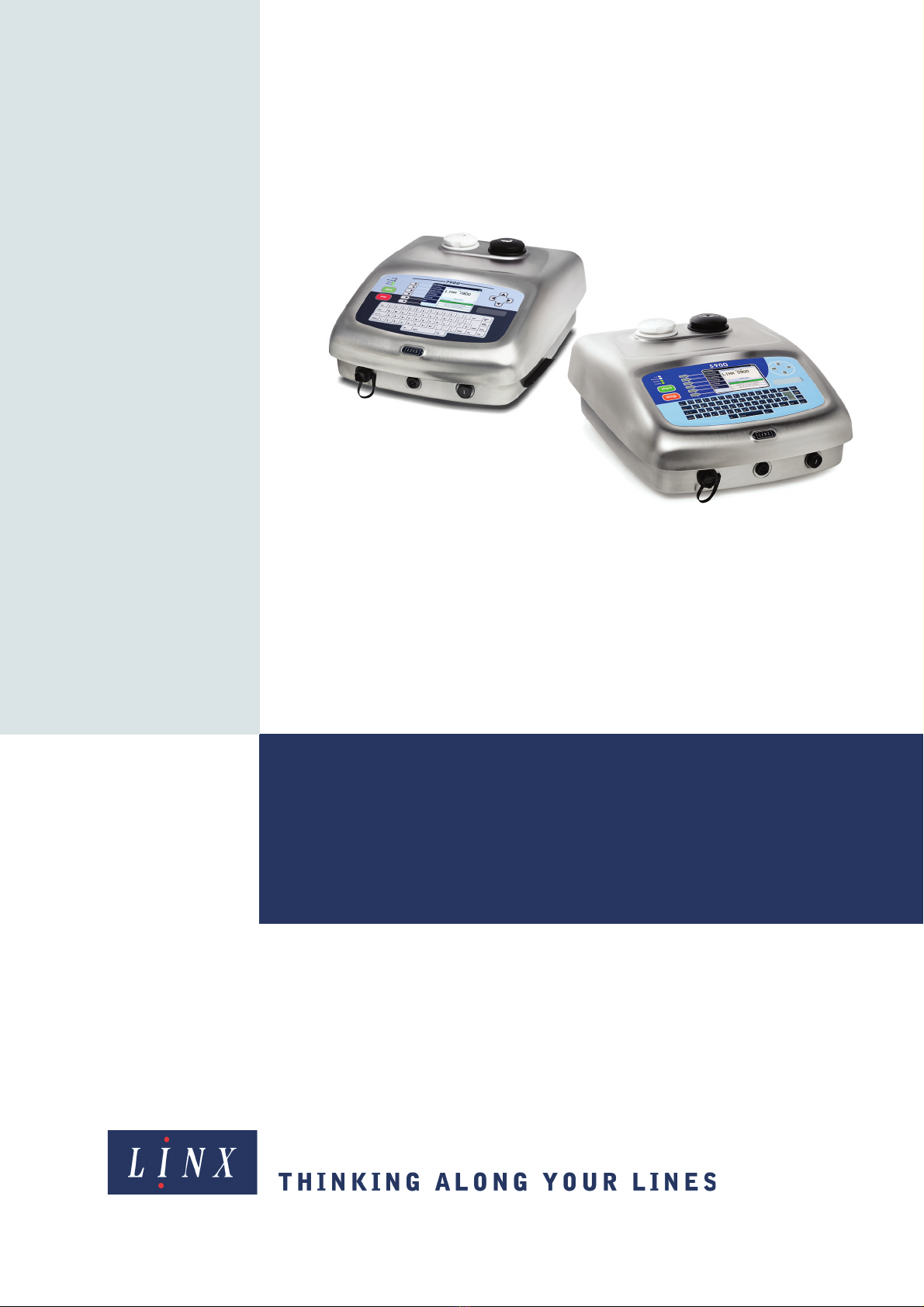
Linx 5900 & 7900 Printers
Linx 5900 & 7900
10 How To Create Bar Codes
This document describes how you create and edit bar codes for the 7900 printer. The printer
can generate bar codes in a number of formats. There are two methods that you can use to
create a bar code:
•Edit an existing field and encode the field.
•Create a bar code field, then enter the source data or link the bar code to an existing
field.
This functionality is not available on the 5900 printer.
11 How To Create a Sequential Number
This document describes how to create a Sequential Number field for the 5900 and 7900
printers. A Sequential Number field is a field that contains a number that is updated
automatically. The printer updates the number at each occurrence of a trigger event, which
you can define.
12 How To Use the Spectrum Printer
This document contains additional information for anyone who uses the 7900 Spectrum
printer. The guide includes information about the Mixing Sequence, system events, and
maintenance.
13 How To Create a Remote Field
This document describes how to create a remote field for the 5900 and 7900 printers. A
remote field in a message reserves an area that you can use for data downloaded from a
remote computer or other equipment. A single message can have more than one remote
field, and you can use the remote field data in more than one message.
14 How To Create a Production Schedule
This document tells you how you create a Production Schedule for the 7900 printer. A
production schedule allows you to print a sequence of messages automatically. You can set
the number of repeats for each message, or use a trigger signal to change to the next
message. You can use an external device or an internal signal (for example, the time or date)
to provide the trigger signal.
This functionality is not available on the 5900 printer.
15 How To Use the Parallel I/O Option
This document tells you how to configure the Parallel I/O (Parallel Input/Output) option on
the 5900 and 7900 printers. This option allows a remote host device (PLC or computer) to
control the printer, or monitor the printer status.
16 How To Use the Communications Options
This document describes how to set up the 5900 and 7900 printers for remote
communications. The printers use protocols to enable communication with remote devices
like bar code scanners, programmable logic controllers (PLCs) and PCs. You can use remote
devices to control the printers and to download messages and data for printing.