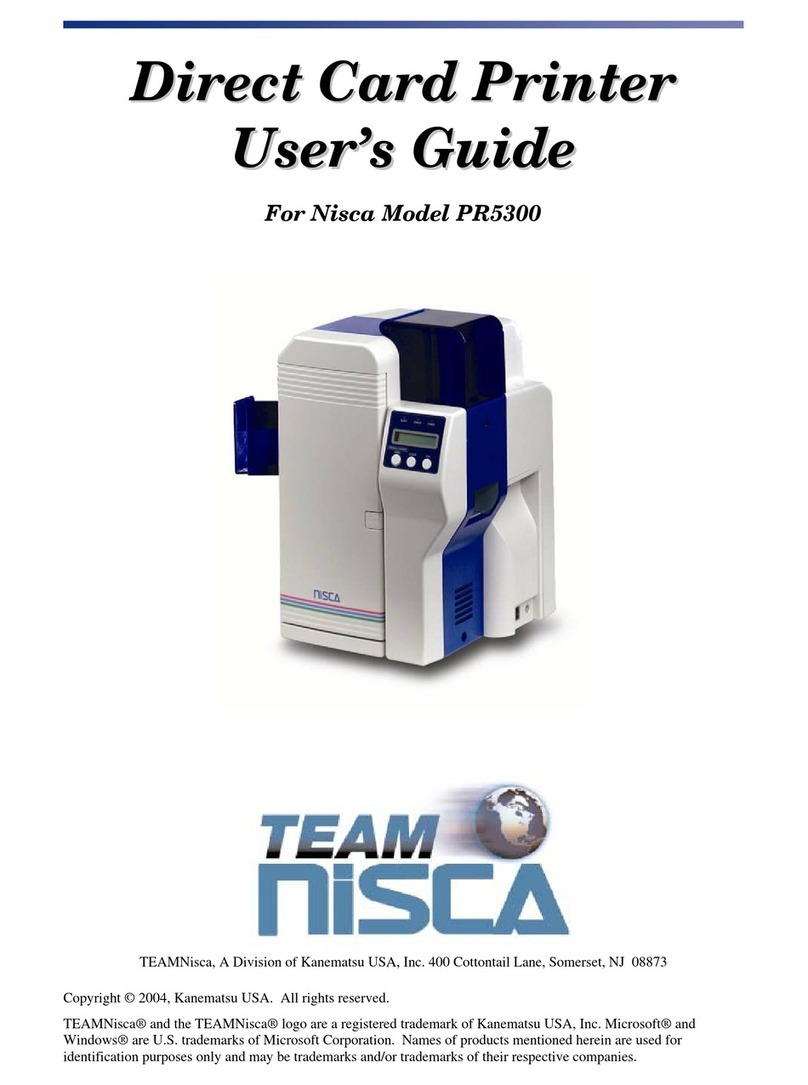
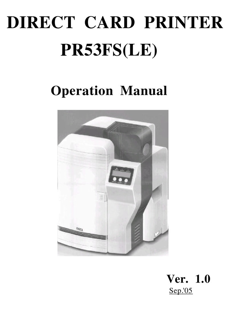
Nisca PR5350 User manual

DIRECT CARD PRINTER
PR5350
Service Manual
Ver. 1.0
Aug.'05

Contents
Section 1Overview
1.Outline of Equipment
1.Description of Equipment
2.Basic Specifications
2.Mechanical Operation
3.Electrical Operation
1.Electrical Block Diagram
2.Main Circuit Board
3.Interface Board
4.Operation Panel Board
5.Mechanical Actuators
Section 2Setting Up
1.Setting Up
1.Caution for setting up
2.Space for installation
3.Connection to Host Computer
2.To put aENCODER in the printer
1.Procedure to put in
Section 3Operation Panel
1.Overview
2.Description of Operation Panel
3.Internal Modes of Printer.
1.Operation of Service Mode
2.Structure of Service Mode menu
3.Description of Service Mode
4.Structure of Service Mode Menu
Section 4Maintenance
1.Maintenance List
2.Method of Maintenance
1.Cleaning Rubber Roller
2.Applying grease to Pulley Shafts etc.
Section 5Replacement and Adjustment
1.Replacing Main Board
2.Adjustment after Main Board replaced
1.Adjusting the Print Position
2.Adjustment of Print Uniformity
3.Adjustment of Print Density
4.Adjustment of Sensor Level
3.Adjusting density of LCD Display
4.Adjustment for Card Thickness

Section 6Troubleshooting
1.Troubleshooting with the display on the LCD
1.Description for the message on the LCD and meeting of recovery
2.Checking and repairing of the troubles
3.Troubles on communication with PC
2.Errors which can not be checked on the LCD panel
3.Card JAM Locations
Section 7Appendix
1.Harness Connection
2,Electric Parts Layout
3.Parts Guide

Section 1 Overview
1. 1 Outline of Equipment
1.1.1 Description of Equipment
This equipment is a full color card printer to print image, characters and protective
overlay on a plastic card based on the data supplied from personal computer.
Printing method is dye sublimation heat transfer printing for color image and heat
melted ink transfer printing system for characters (black)and protective overlay. With
standard built in Flip Turn Block, both side printing is possible in single operation.
Magnetic encoding is possible on the magnetic stripe of the card by connecting
Magnetic Encoding Unit, which is available as an optional unit. Also, as an option, Heat
Roller Unit is available for printing hologram coating and thicker protective overlay.

1.1.2 Basic Specifications
Printing method Image Area: Dye Diffusion Thermal Transfer
Character Area: Molten Type Thermal Transfer
Protective Layer: Molten Type Thermal Transfer
Printing Media PVC Card (Recommended Card by NISCA)
Size:Conform to JIS X 6301 (ISO standard CR-80)
Thickness:Conform to JIS X 6301(ISO standard CR-80)
Printing
Resolution
300dpi (11.81dots/mm)
Printing
Grayscale
Input:256 grayscale for each colors R,G and B
Output:256 grayscale control for each colors C,M and Y
Printing Size Max. 85.5mm(card longitudinal)
×54mm(card transverse direction)
Printing
Arrangement Area
Max. Entire area
Printing Speed 45seconds per card excluding communication time at the
whole area printed as mentioned above.
Supply method
and capacity
100 cards(card thickness:0.76mm);supplied automatically
Interface SCSI or USB 2.0 (Fixed in factory)
Power supply AC 100~240V 50/60Hz
Power
consumption
120W max.
Equipment
dimensions
421mm(H)×271mm(W)×331mm(D)
(excluding Stack Box)
Equipment weight
13kg:Main body
13.8kg:Including optional magnetic encoder

1.2 Mechanical Operation
This equipment consists of Card Supply Block, Flip Turn Block,
Card Ejection Block, Card Encoding Block and Card Rejection Block.
?
?Card Supply Block
Card Supply Box can contain up to 100 pcs of standard plastic cards(0.76mm
thick)so that a continuous printing of high volume card is possible.
The box is made of a transparent plastic for easy checking of the remaining card
supply and protecting the cards from dust. The card is fed from the bottom of the
pile and automatically transported in the printer. A weight plate is provided to
ensure the positive feeding of cards when the remaining cards becomes low.
Card separation is done by the gate at the entrance, which can be adjusted to
various thickness of cards.
?Card Cleaning Block
There are two rubber rollers with sticky surface to remove dust .One is for front side of a
card and the other is for back side of the card. Since this printer has this feature it is
possible to make printing process faster and clear at dual side printing.
It is necessary to clean them periodically to let them keep this performance.
See section4 for how to clean them.

?Flip Turn Block
Turns the card for both side printing. This block also serves to switch the card
path to Print Block, Eject Block and Reject Block. It is possible to rotate the this
block manually. Never touch the part besides green color part when you need to
rotate this block manually.
?Print Block
The card moves back and forth in the Print Block 5 times to be printed with 3
colors, black and overlay. Print Block consists of Card Transport Module, Print
Head Module and Ribbon Feed Module.
In the Card Transport Module, the card is transported by two pairs of capstan
rollers placed in front and behind platen roller. While printing, the nip release
mechanism works to eliminate the shock of the card entering the printing block and
provide a smooth and clear printing. Each roller is precisely driven by stepping
motor to minimize the color deviation and the side of the card is controlled to limit
skew. A high resolution (300 dpi)thermal head is used in the Print Head Module
for clear and high quality image printing. An even pressure is given to the thermal
print head by two coil spring located at both end of the head to maintain uniform
contact to the card. The thermal head is assembled in one independent unit so that
the replacement is made very easy. Also a user can replace the print head and
ribbon at front side by featuring front access system.
Ribbon Feed Module has Feed Bobbin, Transport Roller, Take-up Bobbin and
driven by each independent torque limiter so that the ribbon can be fed with
constant tension for stable printing. Take up bobbin is driven at two speeds, slow
for printing and high for non-printing, which makes the efficient operation possible.
?Card Encode Block
Magnetic Encode Unit, IC Encode Unit, etc are available for this printer as optional
unit. By mounting the Encode Unit, printing of image and characters, encoding
Magnetic (or IC )data can be processed in one operation in one equipment. As the
Encode Unit can be mounted in the Printer, it does not require additional desk space.
?Card Reject Block
If a trouble occurs while printing, the printer stops automatically. In such case, by
pressing "Clear" key, the card currently being printed will be ejected through
Reject Exit.
?Card Ejection Block
Card Ejection Block has a transparent card stack box. The printed cards are ejected
in this box and stacked (100 cards of standard thickness ).
The box has a cut out for easy removal of the printed cards.

1.3 Electrical operation
1.3.1. Electrical Block Diagram
Operation Thermal
Panel Board Head
Main Circuit Mechanical
Board Actuators
Interface Power Supply
Board Unit
Printer Unit Block Diagram
The Printer Unit is controlled and driven with the following components.
?Main Circuit Board (PBA-MAIN)
Receives commands and data from the host through SCSI interface and controls the
operation of the Printer Unit, also controls the thermal print head according to the
image data.
?Interface Board (PBA-I/F-SCSI or PBA-IF-USB)
Controls the SCSI or PARALLEL interface.
For SCSI :It has connector and terminator switch for SCSI interface and has
connector for optional units.
For USB : It has a connector for USB interface and has connector for optional
units
?Operation Panel Board (PBA-OPEPANE)
Constituted with LCD, LED, Push Buttons, and controlled by the Main Circuit
Board.
?Power Supply Unit
Supplies DC24V, and DC5V to the Printer Unit and Optional Unit.
?Thermal Head
Supplies head energy for printing the image, characters and OP (over coat).

?Mechanical Actuators
Consists of sensors and the motors to transport the cards.
1.3.2 Main Circuit Board(PBA-MAIN)
There are CPU Block, Memory Block, Actuator Control Block.
Following items are the main components:
?32 bit CPU (IC1)
32 bit single chip micro processor, activated on the clock of 12.5 MHz
?Flash Memory(IC8)
A memory of 4 M bytes for storing the firmware.
It can be downloaded through the SCSI or USB interface.
?SRAM(IC9)
1 M byte memory to be used for cash memory of CPU(IC1).
?EEPROM (IC4)
4K byte memory to record total frame number, number of errors, setting values of
the specific unit, etc.
?Serial interface driver (IC33)
Translated the signal of CPU to RS232C for communication with the built-in encoder
unit.
?SDRAM (IC14)
Memory of 16 M byte which stores the data of RGB +characters for 2 frames.

?DSP (IC3)
Digital Signal Processor works for color changing or enhance of edge of an image.
?Control IC (IC2)
A Gate array to control the printer activated on the clock of 20 MHz.
This IC controls following items by setting from CPU
>To control the transfer of the image data to DRAM and also image rotating function.
>To control the thermal head
>Interface for SCSI or USB 2.0 control IC
>To control the LCD
>To supply driving signals for PM 1-3
>To generate the control signal for DM1
>To control sensors
1.3.3 Interface Board (PBA-I/F)
Interface board applies to SCSI-2 or USB 2.0 standard.
<SCSI 2 type interface board>
There are two "half 50" pin connectors on the interface board. Also, there is a
connector for connecting the optional device.
?Serial interface driver (IC4)
Translates the signal of CPU to RS422 level for the communication with the
attached optional equipment.
?SCSI Controller (IC2)
Operates on the clock frequency (OSC1)of 20MHz and controls SCSI bus.
?SCSI terminator (IC3)
An active terminator IC supporting the SCSI specification, which terminates the
SCSI
bus by the input of the switch (SW2)located on the backside of the printer.
<USB 2.0 type interface board>
There is B type connectors on the interface board. Also, there is a connector for
connecting the optional device.
?Serial interface driver (IC2)
Translates the signal of CPU to RS422 level for the communication with the
attached optional equipment.
?USB controller (IC1)
Controls the interface USB 2.0 bus. (generated by OSC1)

1.3.4 Operation Panel Board (PBA-OPEPANE)
Operation Panel is used to indicate the current status of the Printer to the operator, to
change setting, execute printing, and clearing errors.
?LCD (IC1)
LCD panel of 16 characters * 2 lines. Displays the condition of the printer, setting and
changes of values, error messages, etc.
?LED1 -LED3
Indicate the Printer condition to operator.
?SW1 -SW3
Switches for operator to operate the Printer.
Note: Details of operating the Operation Panel is explained in Section 3,
Operation Panel.

1.3.5 Mechanical Actuators
The Printer Mechanism consists of Sensors and Motors, etc.
<Input mechanisms>
Symbol Component Function
SN1 Optical Sensor
Detection of card empty at Card Supply
Block.
SN2 Optical Sensor
Detection of card position
(Just before Cleaning Roller).
SN3 Optical Sensor
Detection of card position
(Just before Flip Turn Unit).
SN4 Optical Sensor
Detection of card position
(Just before Print Block).
SN5 Optical Sensor
Detection of card position
(to detect the leading edge of a card).
SN6 Optical Sensor
Detection of the home position of Flip Turn
unit.
SN7 Optical Sensor
Detection of the angle of Flip Turn unit.
SN8 Optical Sensor
Detection of length of ribbon fed.
(taking up side)
SN10 Optical Sensor
Detection of mark on the ribbon.
SN11 Optical Sensor
Detection of print head position.
SN12 Optical Sensor
Detection of print head position.
SN13 Micro switch Detection of open/close of Front Cover.
(with interlock function)
SN14 Micro switch Detection of open/close of Top Cover.
(with interlock function)
SN15 Optical Sensor
Detection of card position
(just before encoder )only available when Encoder
set.
SN18 Optical Sensor Detection of length of ribbon fed.
(supply side)
<Output Mechanisms>
Symbol Component Function
DM1 DC Motor Rolls up Ink Ribbon.
Moves (up/down)Thermal Head
PM1 Pulse Motor Drives rotation mechanism in Flip Turn Block.
Transports a card (Card Supply Block)
PM2 Pulse Motor Transports a card (Flip Turn Block)
PM3 Pulse Motor Transports a card (Print Block)
HFAN Fan Motor Cools Thermal Head.
DFAN Fan Motor Cools Power Supply.

Section 2 Setting Up
2. 1 Setting Up
2.1.1 Caution for setting up
Dusty place must be avoided for using this equipment because the printing system of this
printer is especially sensitive to dust. When printing on the card with magnetic stripe, do
not place the printer at near the equipment which is emitting magnetic field.
Other than above, use general caution for setting up other OA equipments and choose
proper place with proper environment. For further details, please read operation manual.
2.1.2 Space for installation
The space for the operation as
shown in the illustration should
be provided.
?At least 50 cm(20 inch)of
clearance should be kept for
the Top Cover.
?Table to place the printer
should be able to hold
minimum 14Kg(31lbs)and
have flat top and 4 rigid legs.
?It should not incline more
than 1?.

2.1.3 Connection to Host Computer with SCSI or USB
<SCSI type interface>
1)Connection of SCSI Cable
Connect the Printer, PC and Peripheral Units with SCSI Cable.
The Printer is equipped with two female connectors of 50 Pins (half type)of SCSI
specification. Use suitable SCSI cable with suitable connectors to match the PC and
Peripheral Units.
Note 1: Total length of the SCSI cable should be within 6 meters.
To ensure stable operation, within 4 meters is recommended.
Note 2: Pleaseuse the SCSI -II specification high impedance cable. In case of daisy
chain connection, operation may become unstable unless all cables are SCSI-II
specification.
Note 3: Turn OFF power switches of the Printer, PC and all units when connecting the
cable. The retaining hook should be securely latched.
Note 4: On the backside of the Printer, OPTION CONNECTOR located next to SCSI
connectors is the connector for the Optional Units of this card printer only.
Do not connect any other unit. It may cause a trouble.
Interface connectors

2)Setting internal SCSI Terminator.
The Printer has Active Terminator for SCSI-I and SCSI-II.
When using the Terminator, turn the switch at the back of the Printer ON (upper side).
(Turn OFF the power switch when operating this.)
To switch on
To switch off
Appearance of Terminator switch
3)Setting SCSI ID Number
The SCSI ID number can be freely selected from 0 to 7 through the operation panel of
the printer.
Default ID setting is 4.
Note 1: Do not set the same ID number as the PC and other peripheral units. (It may
cause a trouble.)
When setting, check the ID numbers of the other units.
Note 2: When setting the ID number, turn OFF the power switches of PC and all other
peripherals.

<USB type interface>
1)Connection of USB Cable
Connect the Printer, PC and Peripheral Units with USB 2.0 Cable.
The Printer is equipped with B type connector
Note 1: Turn OFF power switches of the Printer, PC and all units when connecting the
cable.
Note 2: On the backside of the Printer, OPTION CONNECTOR located next to USB
connector is the connector for the Optional Units of this card printer
only. Do not connect any other unit. It may cause a trouble.

2.2 Installation of the Encoder Unit
2.2.1 Installing steps
Step 1 Turn OFF the printer power source.
Step 2 Remove RIGHT-COVER. (Remove 2 x M-4 screws )
Step 3 Take the screw off to take out a slide for a card rejected .
Step 4 Insert the ENCODER into the encoder space of the printer with connecting the
two harnesses from the printer.
Step 5 Fix the ENCODR with the screw of which was removed in Step3.
Step 6 Put the small Exsit Cover on the RIGHT-COVER with two screws.
The Exit Cover and two screws are supplied with ENCODER.
Step 7 Put the RIGHT-COVER back to the printer and fix with 2 x M-4 screws
Step 3 Step 4
Step 5 Step 6

Section3OperationPanel
3.1 Overview
Operation panel of PR5300 is used as a communication interface with the operator.
The Operation Panel has functions to display the printer setting such as image memory
mode, ink ribbon selection etc and to check the condition of the printer operation such
as finding the cause of error for trouble shooting, Printer adjustment, checking condition
of operation etc as well as to show the current operating status of the printer.
3.2 Description of Operation Panel
Refer to Section 4 of the Operation Manual of PR5350.
3.3 Internal Modes of Printer
There are three Operation Panel Modes for PR5350 as following
1. Normal mode Display the current operating status, such as error, of the Printer during
the print operation. The Printer is in this mode when the power is
turned ON. Refer to Operation Manual of PR5350 for the actual operation.
2. User mode This mode is used to set the Printer conditions such as setting of
image memory, ink ribbon selection etc. Also, used to show the
information such as the ROM version etc. For the operation refer to
the Operation Manual. In this section of this booklet, print mode only
is explained.
3. Service Adjustment of the Printer, such as the print density etc, is done in this
mode mode. Also, this mode is used for analyzing the cause of troubles such
as checking the condition of sensors and operation of individual
actuators. Details of this mode is described in this section.

3.3.1 OPERATION OF SERVICE MODE
Service mode is the mode for the service person to adjust and check performance of the
printer. The image data in the printer is cleared when switched to and from the service
mode.
Switching to Service Mode
?To switch to service mode,
1. Return from the other mode to Normal Mode.
2. In the idle or error mode, keep the MENU key pressed till it becomes
Command Reception Mode. ("Input Command" appears on the LCD panel)
3. While pressing the MENU key, press EXE and CLEAR keys alternately
(about 8 times )till the display changes from "Input Command" to "Service Mode".
4. Release the MENU key.
?Moving in the Same Directory
To move in the directory, press MENU key to change the menu. MENU will change
in the set order when the key is pressed.
?Execution of a menu
See section 3.3.2 and 3.3.3 for operation of current menu.
?Moving to the Lower Layer Directory
To enter into the directory of the lower layer from the present layer, press EXE key
at the appropriate menu.
?Returning to the Upper Layer Directory
To go one layer higher than the present, switch the menu to "Return to Parent Menu"
and press EXE key.
?Returning to Normal Mode
Switch the menu to "Return to Normal Mode" and press EXE key or switch the
menu to "Return to Parent Menu" and press CLEAR key.

3.3.2 Menu Structure of Service Mode
The Menus of Service Mode are as follows. The part in rectangle will be displayed only
when the referred optional units are connected.
Service Mode SN01 02 03 04 05 ISO Track1
CLR:Back EXE Go EXE:Encode
SN06 07 08 09 10 ISO Track2
EXE:Encode
Adjustment Mode SN11 12 13 14 15 ISO Track3
EXE:sub menu EXE:Encode
Sensor Check SN16 17 18 JIS2
EXE:sub menu EXE:Encode
Actuator Check SN10 Analog Disp Return to Parent
EXE:sub menu Menu (CLR/EXE)
Eject Position Auto Adjustment
EXE:sub menu EXE:Adj Start
User Menu Config Return to Parent IC-R/W Test
EXE:sub menu Menu (CLR/EXE) EXE:Entry/Eject
Encoder Check Return to Parent
EXE:sub menu Menu (CLR/EXE)
IC-R/W Check Stack Position
EXE:sub menu
H.Roller Check Reject Position Heat Total Time
EXE:sub menu
Error Display Select Action Position Adj.
EXE:sub menu
Return to Normal Print Number Position Adj.
Mode (EXE) EXE:Test Print
Card Pass Test Sensor Adj.
EXE:Start (Auto) EXE:Start
Return to Parent Return to Parent
Menu (CLR/EXE) Menu (CLR/EXE)
Ribbon Menu Disp
Error Rate
Adjust Menu Disp Error Log Disp
Status Menu Disp Error Code rate
Return to Parent Error Log Reset
Menu (CLR/EXE)
Return to Parent
Menu (CLR/EXE)
?
?
?
?
?
?
?
?
?
?
Other manuals for PR5350
1
Table of contents
Other Nisca Printer manuals
