Nitek ER8400C User manual

INSTALLATION GUIDE
NITEK®
De Schans 19-21 2a
8231 KA Lelystad
Tel: +31(0)320-230005
Fax: +31(0)320-282186
WWW.NITEK.NL
USA
5410 Newport Drive, # 24
Rolling Meadows, IL 60008
Phone: (847) 259-8900
Fax: (847) 259-1300
WWW.NITEK.NET
EUROPE
ER8400C
8 Port Wall Mounted IP Video Extender Over Coax
With Built-In Gigabit PoE+ Switch and EtherStretch
The ER8400C is another component of the NITEK cutting edge EtherStretch line. Our EtherStretch solution allows
for the utilization of existing cable infrastructure (coax or UTP) to transmit data from IP cameras and other network de-
vices along with PoE+ power to operate these network devices over the given wire media well beyond the 100m/328ft
networking distance limitation. EtherStretch technology allows you to operate 100Mb Ethernet at over 600 meters.
The ER8400C is a wall mounted eight port power sourcing receiver unit has built-in Layer 2 Gigabit switching capabili-
ties. The unit requires very little installation time and absolutely no set up or configuration. The ER8400C and associ-
ated ET1500C transmitters, up to 8, can quickly enable Coaxial cable to support high speed network communication
and PoE+ transmission to be extended to 500 meters or 1600 feet.
The ER8400C is a fully functional PoE+ Layer 2 switch with IEEE802.3AT power output on each of the 8 EtherStretch
ports and a full Gigabit LAN jack. It allows you to use existing coax cable to install new IP cameras. With EtherStretch
network devices that can extend the network connection to lengths of 500 meters or 1600 feet. The ER8400C require a
small EtherStretch transmitter unit connects at the far end of the cable and allows you to connect any Ethernet device
to the cable and get 100Mb communication.
The ER8400C is completely transparent to the network requiring no IP and MAC addressing. Simply connect your net-
work device to the transmitters network port, connect a new or existing cable to the receiver and the system quickly
begins communicating. LED indicators show the status and data speed of communications along with PoE power con-
firmation.
The NITEK EtherStretch ER8400C reliably extends network communications to overcome cable distance limitations
offering connectivity to devices in locations traditional networking does not allow. The ER8400C is ideal for retro-fitting
existing installations. The wall mounted unit is constructed of robust welded steel casing with a security lock and a built
in cooling and ventilation system.
Description
RoHS
COMPLIANT
2002/95/EC
IEC/UL 60950-1

Read all Safety Instructions.
Keep the Instructions for future reference.
Be sure to HEED all Warnings.
Follow ALL instructions.
DO NOT use this device or any of the equipment described, near water.
Clean this device ONLY with a dry cloth.
DO NOT block any ventilation openings.
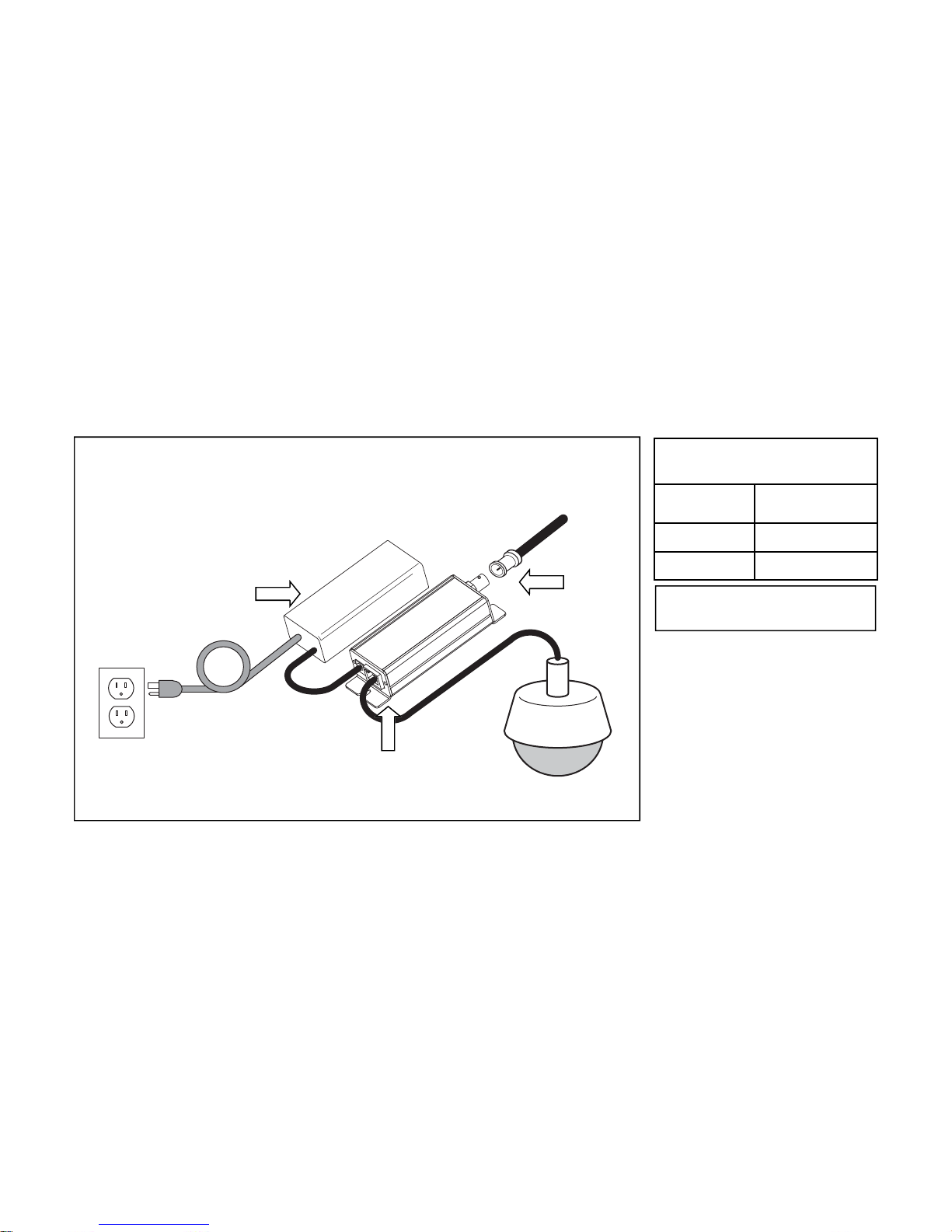
Install in accordance with the manufacturer’s instructions.
DO NOT install near any heat sources such as radiators, heat registers, stoves or other apparatus (including
amplifiers) that produce heat.
DO NOT defeat the safety purposes of polarized or grounding type plugs. A polarized plug has two blades, with
one blade wider than the other. A grounding plug has two blades and has a third grounding prong. The wide
blade and the grounding prong are provided for your safety. If the provided plug does not fit into your outlet,
consult an electrician for replacement of the obsolete outlet.
DO NOT connect the unit to an electrical supply if the wiring or over current protection of the supply could be
overloaded when the ratings listed on the unit are considered.
Protect the power cord from being walked on or pinched especially at plugs, convenience receptacles and other
points where they exit from the device.
Only use attachments and/or accessories specified by the manufacturer.
Refer all servicing to qualified service personnel. Servicing is required when the device has been damaged in any
way, such as the power supply cord or plug is damaged, liquid has been spilled on, or objects have fallen into the
device, the device has been exposed to rain or moisture, does not operate normally or has been dropped.
WARNING: To reduce risk of fire or electric shock, do not expose this apparatus to rain or moisture.
Installation shall be performed ONLY by qualified personnel and must conform to all local codes.
Unless the device is specifically marked as a NEMA 3, 3R, 3S, 4, 4X, 6 or 6P enclosure, it is designed for indoor
use ONLY and it must not be installed where exposed to rain or moisture.
Important Safety Instructions

Parts of the ER8400C (Front Panel)
LAN
ETHERSTRETCH
NITEK
®
POWER
TROUBLE
10 Mbps
100 Mbps
1000 Mbps
LAN
PoE
10 Mbps
100 Mbps
PORT 1PORT 2PORT 3PORT 4PORT 5PORT 6PORT 7PORT 8
87654321
Network Connection
Green
= 1Gb
Yellow
Yellow
Yellow
= 100Mb
Orange = 10Mb Coax BNC Connectors
LED Display Panel
The LED Display Panel shows the same
information as the individual jacks does but
in a easier to read location. It also shows
Power indicator and a Trouble LED.
Trouble LED
Solid if there is a temperature problem
Flashing Slow is a network loop problem
Installation Considerations
Wire and Cable Recommendations: The ER8400C is designed for use with up to 8 coaxial cables. The quality
and condition of which must be considered serviceable cable. It must be free from damage such as cuts, breaks or
cracks to the outer covering and insulated shielding which may compromise the signal conductivity of the cables.
For more specific information regarding wire types, gauges, and proper installation techniques please call Tech
Support at (800) 528-4343.
Ethernet & PoE: The ER8400C is designed to communicate at up to 100Mbps per network port for Ethernet data
and transmit up to a Gigabit of aggregate LAN traffic. Additionally, the ER8400C provides per port power sourcing
PoE+ voltage to operate the transmitters (ET1500C), and up to 8 attached network devices. As a power sourcing
Layer 2 switch the ER8400 will supporting 15.4W (802.3af) to 25.5W (802.3at) powering schemes at a maximum
distance of 1600ft or 500m. Refer the PoE distance chart for specific power capabilities. Before installing this solu-
tion be sure that the cable involved does not exceed the recommended maximum lengths. If the cable length is in-
determinist at the time of installation, we recommend the use of a time domain reflectometer (TDR) which can
measure impedance characteristics, splices, and determine the cable length. The TDR does this through the use of
short rise time pulses.

Installment Topology
Equipment Requirements & Mounting: The process for installing the ER8400C is rather quick and easy. A com-
mon topology involves up to 8 new or existing coax cables (not exceeding 1600ft / 500m), up to 8 ET1500C trans-
mitters and up to 8 IP cameras or other peripheral network devices. The wall mounted ER8400C, which can be re-
ferred to as the NITEK Power Sourcing Equipment (PSE), is compliant with both 802.3AF and 802.3AT devices.
The method for facilitating Ethernet communication and PoE over a coaxial cable starts with connecting the
ER8400C up to 8 coaxial cables via its BNC jacks. Each of the coaxial cables interface with the IP camera via the
ET1500C transmitter, located at the camera end of the cable. The IP camera establishes connectivity to ET1500C
transmitter via RJ5 jacks and a CAT5e/CAT6 patch cords. The ER8400C powers all attached devices within this
system. The Ethernet data from the camera is transmitted over each individual coaxial cable through the ET1500C
to the wall mounted ER8400C in either the IDF or MDF. The aggregate Ethernet data is transmitted to the LAN port
via a built-in Layer 2 switch of the ER8400C. The Gigabit LAN port to ensure congestion-free throughput. An illus-
tration of this system is shown below in the “Installment Topology” diagram.
Upon power up the devices will undergo initialization and auto-configuration which may take a number of seconds
(time variations are device, installation and topology dependent) to complete before PoE and Ethernet communica-
tion commences. For optimal performance referring to the PoE Distance Chart later in this manual. Also adhering to
the IP camera operational specifications is recommended. If issues arise during the installation process please see
the “Trouble Shooting Tips” section later in this manual. You may also contact our web based live tech support at:
www.nitek.net or call (800) 528-4343 in order to speak with one of our engineers directly.
Installation & Setup

Wall Mounting Holes
LAN 8 7 6 5 4 3 2 1
LAN Port Coax BNC Connectors
10.6
10.6
4.0
IEC380 Connector
Security Lock
Parts of the ER8400U (Enclosure)
Device Mounting
Head-end Installation ER8400: The ER8400C is a wall mount unit. When mounting the unit be sure to leave space
on the sides for airflow into the cooling fans and some space on bottom for the power cord.
The BNC ports are designed for connection with standard coaxial cables. These BNC ports are the EtherStretch
ports. The EtherStretch ports are 10/100Mb speed and will run at the highest possible speed given the wire condi-
tions. The ER8400C works like a standard network switch for Ethernet devices but over coax. For long runs of up to
500 meters it is combined with the ET1500C Transmitter to provide a network link. This system normally operates at
100Mb but can adjust for varying wire length and conditions. We refer to the cable between the Head-end and the
transmitter as the Link cable. The speed of the connection is indicated on the LED panel of the unit. A transmitter
must be connected at the far end of the Link cable for the connection speed to be indicated.

Simplified System Hookup Diagram
LAN
ETHERSTRETCH
NITEK
POWER
TROUBLE
10 Mbps
100 Mbps
1000 Mbps
LAN
PoE
10 Mbps
100 Mbps
PORT 1PORT 2PORT 3PORT 4PORT 5PORT 6PORT 7PORT 8
87654321
115/230
VAC
Network Switch,
NVR or Server
ET1500
IP Camera IP Camera
ET1500
Network
Cable
Coaxial
Cables
LAN
Up to 1600 feet /
500m of coax cable
Head-end Installation Continued: Connect the LAN port to your network switch or NVR. The LAN port of the
ER8400 can communicate at up to 1Gbps. The LAN port will automatically sense the connection speed of the net-
work switch, NVR or server. The LAN port is NOT POE capable, only the network ports can provide power to con-
nected devices. The LAN port of the ER8400 will gather data from the network ports and combine it into the higher
speed LAN port. The data speed and POE status for all connected ports is indicated on the LED display panel.
Make sure your network switch can handle the expected data.
Connect main power to the ER8400 using a proper IEC power cord.
After completing the installation of the Head-end equipment, transmitter units must be installed at the remote end.

Transmitter-end Installation
ET1500U Units
At the camera location securely mount the transmitter.
Find the Link cable from the head-end and make sure it is properly terminated. Connect Link cable to the “Link Port”
of the transmitter. If the head-end unit is powered up it will sense the connection to the transmitter and turn on the
power. This will be indicated by the green POWER LED on the “Network Port”. After about 15 to 30 seconds the
orange 10/100Mb LED on the “Link Port” will turn-on to tell you that the system is connected. An Ethernet device
does not need to be connected for the transmitter to communicate with the head-end.
Finally, connect an Ethernet device to the transmitters “Network Port”. If the device requires PoE power, the POE
OUT, green LED on the “Link Port” will turn on followed by the LINK STATUS LED on the “Network Port”. The IP
camera or other Ethernet device should now be ready to operate. Continue installing the remaining transmitters as
needed.
Connec-
tor LED OFF ON FLASHING
Network
Port
Power No power Power
Good
Link
Status
No
Ethernet
Link
Ethernet Link
Good
Link
Port
PoE Out No PoE
Power Out PoE Power
Good
10/100 No Link 100Mb 10Mb
LED INDICATORS
ET1500
IP Camera
Coax from
Head-end
Transmitter Hookup Diagram
Link Port
Network Port

Distance from
Network Port PoE Device Power
Available
30ft/10m 33 watts
325ft/100m 26 watts
Transmitter used as
PoE Injector*
*Results with 48VDC power to the
Transmitter optional Power Port
Optional Hookup for High Power PoE Devices
ET1500U Units
In some cases the PoE device connected to the transmitter needs more power than can be supported over a long
cable run. You can usually identify these cases by watching the POWER LED of the transmitter, located on the
“Network Port”. If the power light cycles ON for less then 1 second and then is off for 3 or 4 seconds when the PoE
device is connected, but it turns ON and operates normally without a PoE device connected, this would indicate you
are having a current limit problem.
You should first check the power requirements of the PoE device. Also check the length of the Link cable from
head-end to transmitter. The POE POWER CHART on the previous page will indicate the maximum power avail-
able for your length of cable.
If the needed level of power is not available for the length of cable, used alternate options are available. One
method is to directly power the transmitter with a 48VDC power supply as shown below (Nitek# PS48). When pow-
ered directly from a 48VDC supply the transmitter can deliver full 802.3AT power regardless of the cable length plus
an additional length of up to 100 meters of network cable.
ET1500
PS48
IP Camera
Coax from
Head-end
48VDC Powered Transmitter Hookup Diagram
Link Port
Network
Port
115 VAC
Optional
48VDC
Supply

PoE Distance Chart
21.7 21.7 18.2
14.4
12.2
25.0
20.0
15.0
10.0
5.0
500 Meters
1,640 Feet
400 Meters
1,300 Feet
300 Meters
1,000 Feet
200 Meters
650 Feet
100 Meters
328 Feet
21.7 Watts 21.7 Watts 18.2 Watts 14.4 Watts 12.2 Watts
Available PoE Wattage At PoE Device
Watts
* Results charted were calculated using RG59U coaxial cable with a 20AWG center conductor.
568B Pinout Termination
12345678
568B
1 WHT/ORG
2 ORG/WHT
3 WHT/GRN
4 BLU/WHT
5 WHT/BLU
6 GRN/WHT
7 WHT/BRN
8 BRN/WHT
PIN COLOR
214
3

Unit Dimensions
10.6
10.6
4.0
IEC380 Connector
Security Lock

Receiver Unit
Network Output Port 1 RJ45 Connector @ 1 Gigabit
Link Port 8 BNC Connectors @ 100Mbps each
Dimensions 10.6”W x 10.6”H x 4.0"D
Operating Temperatures 0° to 52° C / 32° to 125° F
Shipping Weight 12 lbs
Shipping Dimensions 12”W x 12”H x 6”D
Power Requirements IEC380 connector - 110-240VAC/50-60Hz/320Watt Max
LED Connectivity Indicators Link Status, Power, PoE Out, 10/100/1000Mb
Mounting Wall mounting
Humidity Up to 95% non-condensing
Power Output 204 watts Max.
PoE Capabilities Compliant w/ IEEE 802.3af & IEEE 802.3at standards per BNC connector
Troubleshooting
Technical Specifications
PROBLEM POSSIBLE CAUSE
No video/data Check camera and ER8400/ET1500 device connections.
Check Coax cable condition and BNC connector terminations.
Check that the camera is powered.
Check that supplied camera power meets manufacturer’s
specifications.
Check cable that cable distances do not exceed PoE capabilities.
Check that Coax cable length does not exceed the operating distances
of the ER8400 & ET1500.
Check link & device status LEDs.
Video/data loss Check network switch terminations & link status.
Check network routing table.
Confer with site Network Administrator
For Tech Support Call 1-(800)528-4343

Product Warranty and Return Information
Return Policy
A. All returns for warranty, repair, credit or any other reason must be pre-authorized. A return mer-
chandise authorization (RMA) form must be requested from the NITEK Customer Service De-
partment. The form, which will be emailed to the customer, must be filed out completely and
emailed back to the sender at NITEK for approval. An RMA number will be assigned if the re-
quest is approved. In any event, the customer will be notified by NITEK customer service of the
outcome. All approved returns must be shipped freight prepaid, insured and properly packaged.
A copy of the approved RMA form must be enclosed in the shipping container with the goods
being returned and the RMA number must be marked in a visible area on the exterior of the
container.
B. Credit Returns must have been purchased within the last 30 days of the date of the receipt
of the equipment at NITEK. Credit returns must be current products listed on the NITEK
published price list, in effect at the time of the return and must be in new and saleable con-
dition, with all factory packaging. All Credit returns are subject to a restocking charge of up
to 40%. Additional restocking and/or refurbishing charges may be assessed upon inspec-
tion. If it is determined by NITEK that the returned equipment does not meet these condi-
tions, a credit will not be issued.
Lifetime Limited Warranty
Network Extender Products
NITEK warrants the original consumer purchaser that the Network Extender products that it sells
will be free from defects in material and workmanship. If any such product proves defective by our
inspection, after sale to the original consumer purchaser, NITEK, at its option, will either repair the
defective product without charge for parts and labor or will provide a replacement in exchange for
the defective product.
In order to obtain service under this warranty, the customer must notify NITEK of the defect and
shall be responsible for packaging and shipping the defective product to the service location des-
ignated by NITEK with shipping charges prepaid. NITEK shall pay for the return of the product to
the purchaser if the shipment is to a location within the U.S.A. The purchaser shall be responsible
for paying all shipping charges, duties and taxes if the product is returned from a location outside
the U.S.A.
This warranty shall not apply to any defect, failure or damage caused by improper use or improper
or inadequate maintenance or care, or to any product which shall have been repaired or altered
outside our plant in any way, or which has been operated in a manner exceeding its specifica-
tions, or which has had the serial number removed. NITEK shall not be obligated to furnish service
under this warranty: a) to repair damage resulting from attempts by personnel other than NITEK
representatives to repair or service the product; b) to repair damage resulting from improper use
or connection to incompatible equipment; or c) to service a product that has been modified or inte-
grated with other products when the effect of such modification or integration increases the time or
difficulty of servicing the product.
This warranty is given by NITEK with respect to the Network Extender products in lieu of any other
warranties, express or implied. NITEK disclaims any implied warranties of merchantability or fit-
ness for a particular purpose. NITEK’s responsibility to repair or replace a defective product is the
sole exclusive remedy provided to the purchaser for breach of this warranty. NITEK will not be
liable for any indirect, incidental or consequential damages irrespective of whether NITEK has ad-
vance notice of the possibility of such damages.
Table of contents
Other Nitek Extender manuals

Nitek
Nitek VR448COAX User manual

Nitek
Nitek ER1651U User manual

Nitek
Nitek EtherStretch ER8500C User manual

Nitek
Nitek EL4500U User manual

Nitek
Nitek EE328 User manual

Nitek
Nitek Etherstretch EL1500CW User manual

Nitek
Nitek ER8400U User manual

Nitek
Nitek VR148COAX User manual

Nitek
Nitek ER8500U User manual

Nitek
Nitek ET1500UW User manual