Nitek ET1500UW User manual

NITEK®
De Aar 99
8253 PN Dronten
The Netherlands
Tel: +31(0) 321 310 043
WWW.NITEK.NET
USA
5410 Newport Drive, # 24
Rolling Meadows, IL 60008
Phone: (847) 259-8900
Fax: (847) 259-1300
WWW.NITEK.NET
EUROPE
The ET1500U is another component of the NITEK EtherStretch line. Our EtherStretch solution
allows for the utilization of new or existing cable infrastructure (coax or UTP) to transmit data
from IP cameras and other network devices along with power (PoE) to operate these networked
devices well beyond standard network limitations. The system can extend Ethernet to over 600m
or 1968ft of Category cable making the ET1500U is ideal for retrofitting existing installations.
The ET1500UW is a transmitter that mates with any of the EtherStretch Multi-port series receiver
units and require very little installation time and no set up or configuration. This system quickly
turns any ordinary Category cable into a high speed network communication and PoE pathway
well beyond normal limitations. The ET1500UW is completely transparent to the network thus re-
quiring no IP and MAC addressing. Simply connect your network devices to the networking ports
of the ET1500U transmitter and associated receiver along with Category cable run between the
units and the system begins communicating. LED indicators show the status and speed of net-
work communications and PoE power.
The NITEK EtherStretch ET1500UW reliably extends network communications to overcome ca-
ble distance limitations offering connectivity to devices in locations traditional networking does not
allow. The units are constructed of industrial grade RoHS compliant plated aluminum with a corro-
sion resistant finish makes them extremely durable.
Description
INSTALLATION GUIDE
ET1500UW
IP Video Camera Over Coax
Ethernet Extender & PoE Injector with EtherStretch
RoHS
COMPLIANT
2002/95/EC
IEC/UL 60950-1
Patent Pending
08192014

Important Safety Instructions
Read all Safety Instructions.
Keep the Instructions for future reference.
Be sure to HEED all Warnings.
Follow ALL instructions.
DO NOT use this device or any of the equipment described, near water.
Clean this device ONLY with a dry cloth.
DO NOT block any ventilation openings.
Install in accordance with the manufacturer’s instructions.
DO NOT install near any heat sources such as radiators, heat registers, stoves or other apparatus (including
amplifiers) that produce heat.
DO NOT defeat the safety purposes of polarized or grounding type plugs. A polarized plug has two blades, with
one blade wider than the other. A grounding plug has two blades and has a third grounding prong. The wide
blade and the grounding prong are provided for your safety. If the provided plug does not fit into your outlet,
consult an electrician for replacement of the obsolete outlet.
DO NOT connect the unit to an electrical supply if the wiring or over current protection of the supply could be
overloaded when the ratings listed on the unit are considered.
Protect the power cord from being walked on or pinched especially at plugs, convenience receptacles and other
points where they exit from the device.
Only use attachments and/or accessories specified by the manufacturer.
Refer all servicing to qualified service personnel. Servicing is required when the device has been damaged in any
way, such as the power supply cord or plug is damaged, liquid has been spilled on, or objects have fallen into the
device, the device has been exposed to rain or moisture, does not operate normally or has been dropped.
WARNING: To reduce risk of fire or electric shock, do not expose this apparatus to rain or moisture.
Installation shall be performed ONLY by qualified personnel and must conform to all local codes.
Unless the device is specifically marked as a NEMA 3, 3R, 3S, 4, 4X, 6 or 6P enclosure, it is designed for indoor
use ONLY and it must not be installed where exposed to rain or moisture.

Parts of the ET1500UW
Wire and Cable Recommendations: The ET1500UW is designed to use with ANSI/TIA/EIA defined CAT5e
or CAT6 Unshielded Twisted Pair (UTP) cabling. This UTP cable shall be able to accommodate TCP/IP data
operating speeds of 10/100 Mbps transmission rates. The RJ45 termination pin out schemes shall be in
accordance with the 568B standard. The quality of which must be consistent with any reasonably service-
able cable condition. It must is free from damage such as cuts, breaks, or cracks to the outer covering and
insulated shielding which may compromise the signal conductivity of the cable.
For more specific information regarding wire types, gauges, and proper installation techniques please call
Tech Support at 1-(800)528-4343.
Ethernet & PoE: The ET1500UW is designed to transmit and receive up to 100Mbps of Ethernet data and
PoE from 15.4W (802.3af) to 25.5W (802.3at) at a maximum distance of 1968 feet or 600 meters. Before
considering this solution be sure that the cable involved does not exceed the recommended maximum
lengths. If the cable length value is indeterminate at the time of installation, we recommend the use of a
Ohm meter which measures electrical resistance that can be used to determine unknown cable distances.
NEMA4 Enclosure Case: The NEMA4 enclosure is included in order to provided the system (the
ET1500UW transmitter) with a robust degree of weather and atmospheric condition protection in accordance
with the appropriately rated NEMA level. The weatherproof enclosure allows for flexibility in installation and
can be mounted to a variety of surfaces (mounting hardware dependent & not included), either flat or pole
apparatuses. Two (2) water-proof grommets are located at the bottom of the unit in order to secure cable
terminations and case entry points.
NETWORK PORT SIDE
LINK PORT SIDE
Installation Considerations

Installation & Setup
Equipment Requirements & Mounting: The process for utilizing the ET1500UW is rather quick and easy.
A common topology involves lengths of existing or new UTP (CAT5e/CAT6) cable up to 1968 feet or 500
meters, the ET1500UW transmitter and the associated rack mounted multi-port receiver such as the
ER8500C or ER16500C, an IP camera or other peripheral network device. The IP camera must be either
802.3af or 802.3at compliant. That is requiring no more then 15.4 W 48VDC @ 350mA of 802.3af (PoE) or
up to 25.5W 60VDC @ 600mA of 802.3at (PoE+) power for proper attached device operation.
The method for facilitating Ethernet communication and PoE over the UTP cable starts by connecting a
multi-port receiver such as the ER8500U or ER16500U to the lengths of CAT5e/CAT6 UTP “Link” cables.
The IP camera interfaces with the ET1500UW via its “Network Port” labeled RJ45 with a CAT5e/CAT6 patch
cord. The output of the ET1500UW in turn connects to “Link” cables via the “Link Port” labeled RJ45 con-
nector. Power (PoE) from the multi-port receiver provide operational PoE for both the ET1500UW and the
attached the IP camera. An illustration of this is represented below in the “Installment Topology - Type C”
diagram.
Upon final power up the devices will under go initialization and auto-configuration processes (see LED Indi-
cator chart on pg 6) which may take a number of seconds, time variations are device/installation/topology
parameter dependent, to complete before PoE and Ethernet communication commences. For optimal per-
formance referring to the PoE/distance chart (see pg 8) and adhering to the IP camera operational specifica-
tions is recommended. If issues arise during the installation process please see the “Trouble Shooting Tips”
section (pg 9). You may also contact our web based live tech support at: www.nitek.net/index.htm or call 1-
(800)528-4343 in order to speak with one of our engineers directly.
Installment Topology - Type C*
* The ET1500C’s are shown minus the NEMA4 enclosure. Installation of the NEMA enclosed “UW” models and standard
“U” models is the same. Drawing also indicates coax yet the same principals apply in a UTP-CATe/CAT6 scenario.
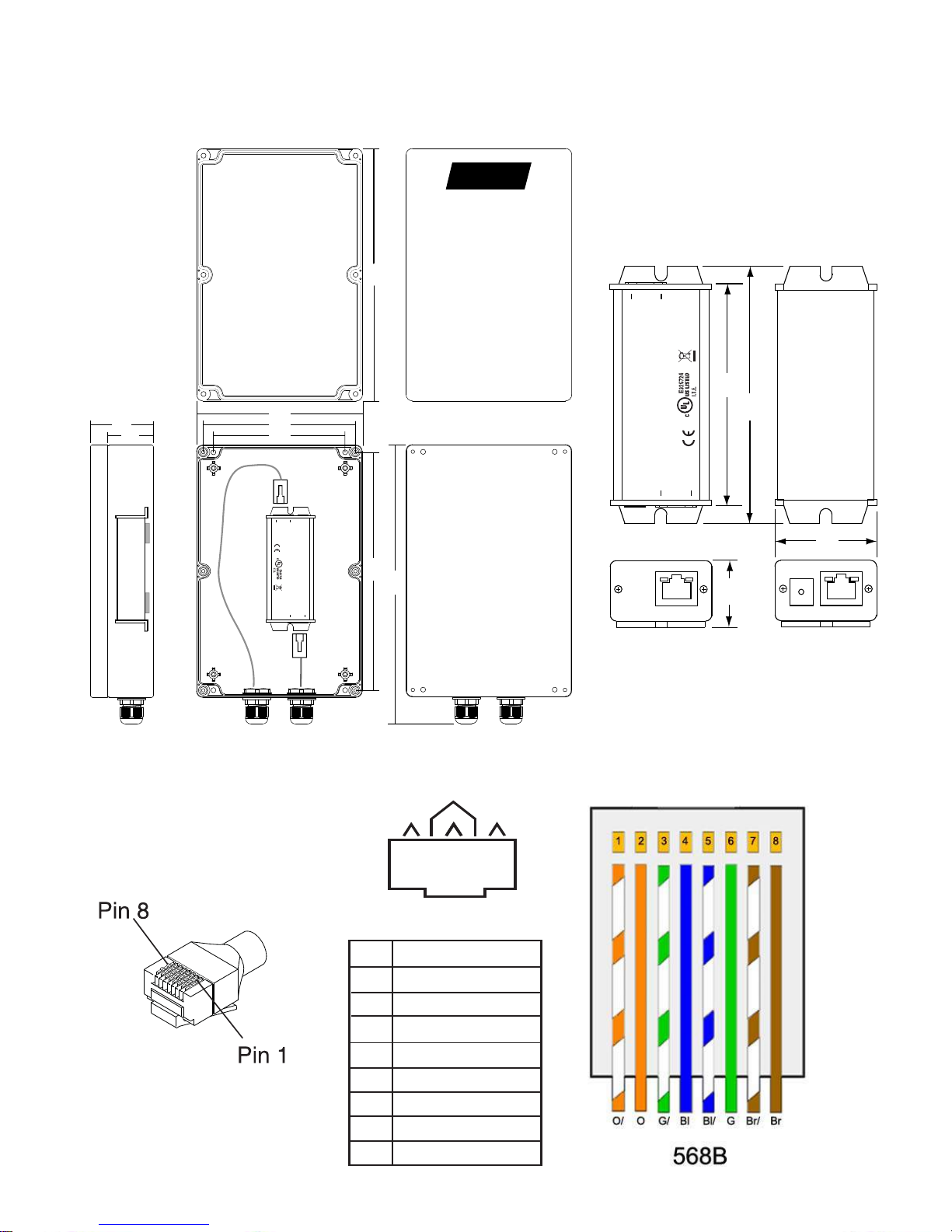
Device Dimensions
568B Pin out Termination
NEMA4 Enclosure
Transmitter
12345678
568B
1 WHT/ORG
2 ORG/WHT
3 WHT/GRN
4 BLU/WHT
5 WHT/BLU
6 GRN/WHT
7 WHT/BRN
8 BRN/WHT
PIN COLOR
214
3
OPTIONAL
Power Input, Class 2
48 to 56VDC, 800mA
Power
Link Status
Network
Port
WWW.NITEK.NET
See Installation Manual
for Hookup Instructions
Made in USA
Link to
Receiver
PoE OUT
10/100
NITEK
®
ET1500U
Transmitter
3.7”
(94)
Top View
Link
P
o
r
t
V
iew
IP Port View Bottom View
4.3”
(109)
1.2”
(30)
1.7”
(43)
5.74
5.27
4.56
8.25
9.92
8.74
Top (Outside View)
Bottom (Outside View)
Top (Inside View)
NITEK
Bottom (Inside View)
2.25
1.58
Bottom (Inside View)
Top (Inside View
)
OPTIONAL
Power Input, Class 2
48 to 56VDC, 800mA
Power
Link Status
Network
Port
WWW. NITEK. NET
See Installation Manual
for Hookup Instructions
Made in USA
Link to
Receiver
PoE OUT
10/100
NITEK
®
ET1500U
Transmitter

PoE Distance Chart
27.427.4
25.0
20.0
18.0
30.0
25.0
20.0
15.0
10.0
5.0
500Meters
1,640Feet
400Meters
1,312Feet
300Meters
984Feet
200Meters
656Feet
100Meters
328Feet
27.4Watts27.4Watts25.0Watts20.0Watts18.0Watts
AvailablePoEWattageAtPoEDevice
Watts
*Resultschartedwerecalculatedusingfourpair24awgCat5ecabling.
14.1
600Meters
1,968Feet
14.1Watts
Connectivity Status
NETWORK PORT SIDE
LINK PORT SIDE
Connector LED OFF ON FLASHING
Network
Port
Power No power Power
Good
Link Status No Ethernet
Link Ethernet Link
Good
Link
Port PoE Out No PoE
Power Out PoE Power
Good
10/100 No Link 100Mb 10Mb
LED INDICATORS

Troubleshooting
PROBLEM POSSIBLE CAUSE
No video/data Check camera, ET1500UW & Multi-port receiver device connections.
Check UTP cable condition and RJ45 connectors.
Check that the camera is powered.
Check that supplied camera power meets manufacturer’s
specifications.
Check that UTP cable distances do not exceed PoE
capabilities. Refer to chart on pg 5.
Check that UTP cable does not exceed the Ethernet data
transmission operating distances of the ET1500UW & ER5U.
Check link & device status. See chart on pg 5.
Video/data loss Check network switch termination(s) & link status.
Check network routing table(s).
Confer with site Network Administrator
For Tech Support Call 1-(800)528-4343
Technical Specifications
Network Transmission Device
Network Port RJ45 Jack
Link Port RJ45 Jack
Ethernet [1] Auto Configuring 100BASE-TX Full Duplex
LED Indicators Link Status, Power, PoE out, 10Mb or 100Mb
PoE Compliance IEEE 802.3af & IEEE 802.3at
Max Operating Distance 1,968ft /600m
Max PoE Operating Distance( See “PoE Distance Chart” on pg 5
Device Power Draw 1.65 Watts
NEMA4 Enclosure Dimensions 2.25” x 5.74” x 9.92” (including water-proof grommets)
Transmitter/Receiver Dimensions 1.2” x 1.7” x 4.3” (including mounting tabs)
Mounting Two 3/8 inch mounting tab slots
Operating Temperature -40° to 75° C / -40° to 167° F
Humidity Up to 85% non-condensing
Shipping Weight 5 lbs

Product Warranty and Return Information
Return Policy
A. All returns for warranty, repair, credit or any other reason must be pre-authorized. A return mer-
chandise authorization (RMA) form must be requested from the NITEK Customer Service Depart-
ment. The form, which will be emailed to the customer, must be filed out completely and emailed
back to the sender at NITEK for approval. An RMA number will be assigned if the request is ap-
proved. In any event, the customer will be notified by NITEK customer service of the outcome. All
approved returns must be shipped freight prepaid, insured and properly packaged. A copy of the
approved RMA form must be enclosed in the shipping container with the goods being returned and
the RMA number must be marked in a visible area on the exterior of the container.
B. Credit Returns must have been purchased within the last 30 days of the date of the receipt of the
equipment at NITEK. Credit returns must be current products listed on the NITEK published price
list, in effect at the time of the return and must be in new and saleable condition, with all factory
packaging. All Credit returns are subject to a restocking charge of up to 40%. Additional restocking
and/or refurbishing charges may be assessed upon inspection. If it is determined by NITEK that the
returned equipment does not meet these conditions, a credit will not be issued.
Lifetime Limited Warranty
Network Extender Products
Nitek warrants to the original End User of Etherstretch products hereunder will be free from defects in ma-
terial and workmanship as of the date of shipment, and that said product will conform to Nitek published
technical specifications as of said date. The foregoing shall apply only to failures to meet said warranties
which appear within that period of time during which the Products are installed in their original installation
for the original End User and operator of such Etherstretch Products; provided, however, that in the event
of product discontinuance, warranty support is limited to five (5) years from the announcement of discon-
tinuance. The duration of the warranty period for products not manufactured by Nitek (e.g., coaxial cabling,
test equipment, power supplies or batteries) shall be the warranty period offered by the original manufac-
turer, if any.
The conditions of any tests shall be mutually agreed upon and Nitek shall be notified of the test, and has
the right to be represented at any and all tests that may be made. The warranties and remedies set forth
herein are conditioned upon proper storage, installation, use and maintenance, and conformance with any
applicable recommendations of Nitek. Additionally, Buyer must promptly notifying Nitek of any defects and,
if required, promptly making the product available for correction.
If any product fails to meet the foregoing warranties, Nitek shall correct any such failure either at its option,
(a) by repairing any defective or damaged product or parts of the products, or (b) by making available any
necessary repaired or replacement products or parts thereof. Any repaired or replacement part or product
shall be warranted for the remaining period of the original Warranty Period. Nitek’s liability with respect to
any product shall not exceed a refund of the price received by Nitek for that product, and in no event shall
Nitek have any liability for any incidental, consequential, special, or indirect damages.
To obtain warranty service, you must first call Nitek and speak to a qualified service representative. If a
return of product is deemed necessary, a Return Authorization number (RA#) will be issued. Upon receiv-
ing a RA#, the product must be shipped back in either its original packaging or packaging providing an
equal degree of protection. This warranty does not cover cosmetic damage or damage due to acts of God,
accident, misuse, abuse, negligence, or modification of, or to any part of the Product. This warranty does
not cover damage due to improper operation or maintenance, connection to improper voltage supply, or
attempted repair by anyone other than a facility authorized by Nitek to service the product. Repair or re-
placement as provided under this warranty is the exclusive remedy of the consumer. This warranty only
covers the first user of the equipment.
Table of contents
Other Nitek Extender manuals

Nitek
Nitek EE328 User manual

Nitek
Nitek VR148UTP User manual

Nitek
Nitek ER1651U User manual

Nitek
Nitek ER8400C User manual

Nitek
Nitek EtherStretch ER8500C User manual

Nitek
Nitek VR448COAX User manual

Nitek
Nitek VR148COAX User manual

Nitek
Nitek ER8400U User manual

Nitek
Nitek ER8500U User manual

Nitek
Nitek Etherstretch EL1500CW User manual


