Nitek ER8500U User manual

INSTALLATION GUIDE
NITEK®
De Schans 19-21 2a
8231 KA Lelystad
Tel: +31(0)320-230005
E-mail: [email protected]
WWW.NITEK.NL
USA
5410 Newport Drive, # 24
Rolling Meadows, IL 60008
Phone: (847) 259-8900
Fax: (847) 259-1300
E-mail: [email protected]
WWW.NITEK.NET
EUROPE
8 Port IP Video Extender Over UTP
With Built-In Gigabit PoE Switch with EtherStretch
ER8500U
The ER8500U is another component of NITEK cutting edge EtherStretch line. Our EtherStretch solution
allows for the utilization of existing cable infrastructure (coax or UTP) to transmit data from IP cameras and
other network devices along with power (PoE & PoE+) to operate these networked devices over the given
wire media well over the 100m/328ft networking distance limitation.
The ER8500U is a Ethernet & PoE extending rack mounted eight (8) port power sourcing receiver unit with
built-in gigabit switching capabilities. The unit requires very little installation time and absolutely no set up or
configuration. The ER8500U and associated ET1500U transmitters (up to 8) can quickly turn ordinary CAT5e/
CAT6 UTP cables into a series of high speed network communication and PoE pathways. The ER8500U is a
fully functional PoE+ network switch with a 802.3AT power output on each of the eight (8) network ports and
can operate with any standard Ethernet device up to 100m. Additionally, when used with the ET1500U trans-
mitters the system allows for cable runs of 600m/1,960ft supplying both a network connection and PoE+ pow-
er.
The ER8500U is completely transparent to the network thus requiring no IP and MAC addressing. Simply con-
nect your network devices to the transmitter LAN ports along with the existing cables to the receiver and the
system quickly begins communicating. LED indicators show the status and data speed of network communi-
cations along with PoE power confirmation.
NITEK EtherStretch ER8500U reliably extends network communications to overcome cable distance limita-
tions offering connectivity to devices in locations traditional networking does not allow. The ER8500U is ideal
for retro-fitting existing installations or for use in lieu of fiber for long distance transmission with the additional
PoE over the link capability. The rack mounted unit is robustly constructed of molded steel casing with appro-
priate built in cooling and ventilation.
Description
IEC/UL 60950-1
Patent Pending

Read all Safety Instructions.
Keep the Instructions for future reference.
Be sure to HEED all Warnings.
Follow ALL instructions.
DO NOT use this device or any of the equipment described, near water.
Clean this device ONLY with a dry cloth.
DO NOT block any ventilation openings.
Install in accordance with the manufacturer’s instructions.
DO NOT install near any heat sources such as radiators, heat registers, stoves or other apparatus (including
amplifiers) that produce heat.
DO NOT defeat the safety purposes of polarized or grounding type plugs. A polarized plug has two blades, with
one blade wider than the other. A grounding plug has two blades and has a third grounding prong. The wide
blade and the grounding prong are provided for your safety. If the provided plug does not fit into your outlet,
consult an electrician for replacement of the obsolete outlet.
DO NOT connect the unit to an electrical supply if the wiring or over current protection of the supply could be
overloaded when the ratings listed on the unit are considered.
Protect the power cord from being walked on or pinched especially at plugs, convenience receptacles and other
points where they exit from the device.
Only use attachments and/or accessories specified by the manufacturer.
Refer all servicing to qualified service personnel. Servicing is required when the device has been damaged in any
way, such as the power supply cord or plug is damaged, liquid has been spilled on, or objects have fallen into the
device, the device has been exposed to rain or moisture, does not operate normally or has been dropped.
WARNING: To reduce risk of fire or electric shock, do not expose this apparatus to rain or moisture.
Installation shall be performed ONLY by qualified personnel and must conform to all local codes.
Unless the device is specifically marked as a NEMA 3, 3R, 3S, 4, 4X, 6 or 6P enclosure, it is designed for indoor
use ONLY and it must not be installed where exposed to rain or moisture.
Important Safety Instructions

Parts of the ER8500U (Front Panel)
1Gigabit LAN Port
8x 10/100 Ethernet “Link” Ports with 10/100
Network Speed & “PoE OUT” LED Indicators
Power & Trouble
LEDs
Installation & Setup
Installation Considerations
Wire and Cable Recommendations: The ER8500U is designed for use with up to sixteen ANSI/TIA/EIA defined
CAT5e or CAT6 Unshielded Twisted Pair (UTP) cables. These UTP cables shall be able to accommodate TCP/IP
data operating speeds of 10/100 Mbps and gigabit rates. The RJ45 termination pin out schemes shall be in accord-
ance with the 568A or 568B standard. The quality of which must be consistent with any reasonably serviceable ca-
ble condition. That is free from damage as in cuts, breaks, or cracks to the outer covering and insulated shielding
which may compromise the signal conductivity of the cables.
For more specific information regarding wire types, gauges, and proper installation techniques please call Tech
Support at 1-(800)528-4343.
Ethernet & PoE: The ER8500U is designed to receive up to 100Mbps (per port) of Ethernet TCP/IP data and
transmit up to 2 Gigabits of aggregate LAN traffic. Additionally, the ER16500U provides per port sourcing PoE to
operate the ET1500U transmitters and any attached network devices while supporting 15.4W (802.3af) to 25.4W
(802.3at) powering schemes at a maximum distance of 600 meter / 2000 feet. Before considering this solution be
sure that the cable involved do not exceed the recommended maximum length. If the cable length value is indeter-
minate at the time of installation, we recommend the use of an Ohm meter which measures electrical resistance to
determine unknown cable distances.

Parts of the ER8500U (Rear Panel)
IEC380 power connector -
115 VAC/240VAC 50/60HZ
Front
Back
Rack Mounting
Device Mounting Options
Wall Mounting
Front
Back
The ER16500U can be rack mounted, wall mounted or used as desk top unit. Use the included mounting ears in the
front or back of the unit depending on your needs. The mounting ears can also be turned to the bottom of the unit
for wall mounting if needed. When mounting the unit, be sure to follow these guide lines.
a. Operating Ambient - Do not install the unit in an assembly where the ambient temperature could exceed
52°C (125°F). NOTE: the ambient temperature in a closed or multi-unit rack assembly could greatly exceed
the ambient temperature outside that assembly.
b. Air-Flow – Leave space on the sides of the unit for airflow into the cooling fans and some space on top of the
unit for air to exit the unit. Adequate air flow is required for safe operation.
c. Mechanical Loading – The mounting ears were designed for two ears to support one unit. Other
configurations, such as mounting other equipment directly on top of the unit or using only one mounting ear,
could cause a hazardous condition due to uneven or excessive mechanical loading.

Installation & Setup
Installment Topology
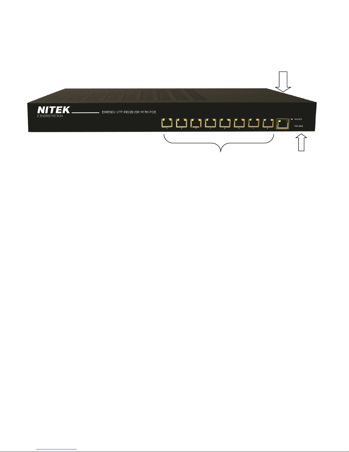
Up to eight (8) NITEK ET1500U’s interface with an assortment of network peripherals providing both power (PoE)
and Ethernet data connectivity over up to eight (8) UTP “Link” cables at the maximum distance of 1,960ft/600m.
The 1Gigabit LAN port on the ER8500U provides congestion-free connectivity to network switches and other LAN
devices for data sorting, storage, and processing. Each port of the ER8500U outputs a max of 25.5W (PoE+)
power and 100Mbps of data bandwidth throughput.
Equipment Requirements & Mounting: The process for employing the ER16500U is rather quick and simple. A common
topology involves up to sixteen (16) existing UTP cables (up to but not exceeding 600m/1,960ft), up to sixteen (16) ET1500U
transmitters, up to sixteen (16) IP cameras or other peripheral network devices (referred to as the Power Device or PD), and
the rack mounted ER16500U (which can be referred to as the NITEK Power Sourcing Equipment/PSE). The ER16500U
NITEK PSE is both 802.3af and 802.3at compliant. That is it produces 15.4W 48VDC @ 350mA of 802.3af as well as 25.4W
54VDC @ 600mA of 802.3at PoE+ power for proper attached device operation.
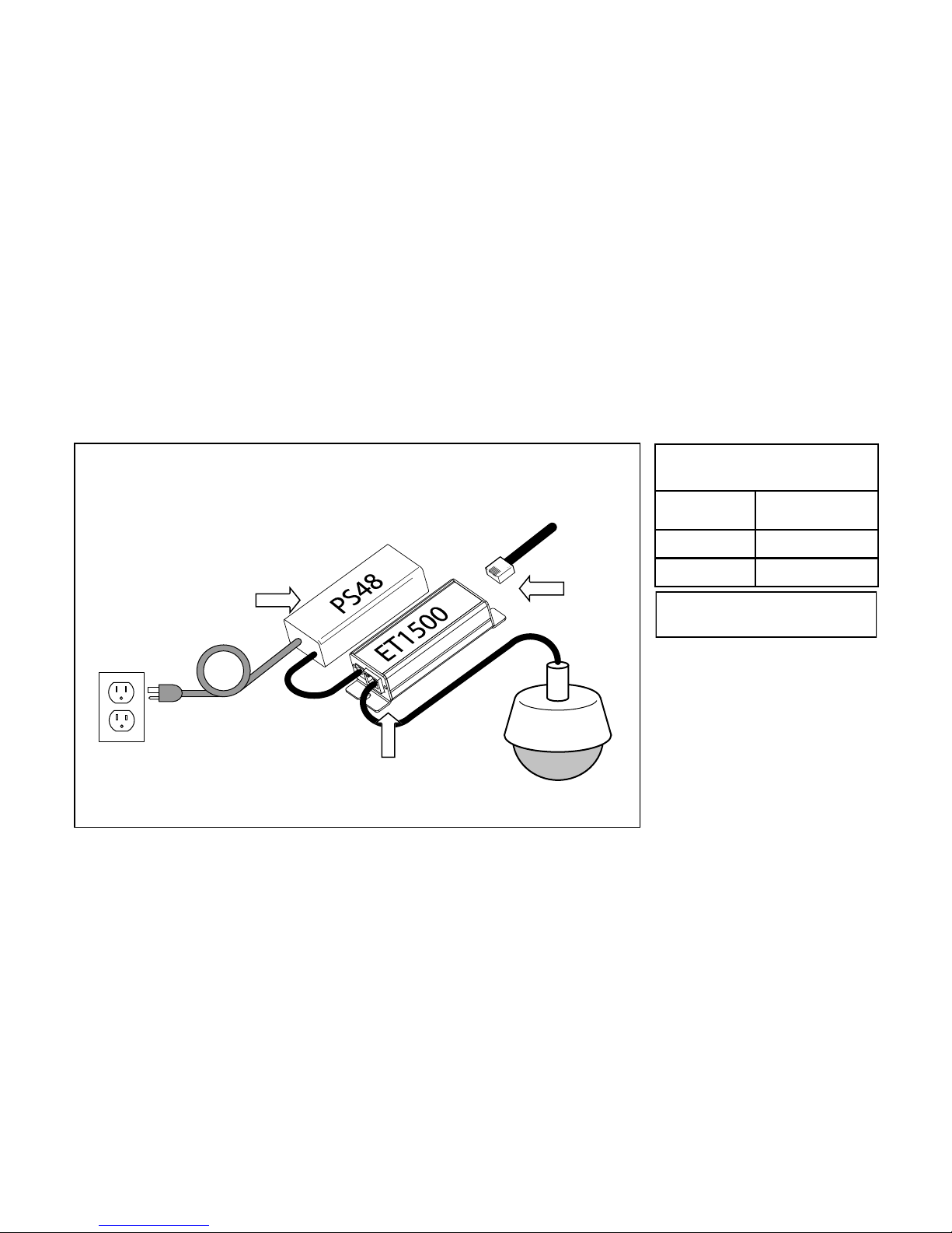
The method for facilitating Ethernet communication and PoE flow over CAT5e/CAT6 UTP cable starts with connecting the
ER8500U NITEK PSE with up to eight (8) UTP “link” cables via the RJ45 connectors. The CAT5e/CAT6 cables interface
with the IP camera or other PD via the ET1500U transmitters. The IP camera / PD establish connectivity to ET1500U via
RJ45 jacks and a CAT5e/CAT6 patch cords. The ER8500U powers itself and all attached devices within in this local net-
work/system. The IP data from the PD is transmitted over each individual UTP “link” cable through the ET1500U to the rack
mounted ER16500U in either the IDF or MDF. The aggregate PD data is transmitted to the greater LAN or WAN via a giga-
bit LAN ports labeled and located on the front of the NITEK PSE. Also commonly done is to use the LAN port to chain two or
more ER8500U units together via a separate network switch. This will provide a way of bring greater numbers of cameras
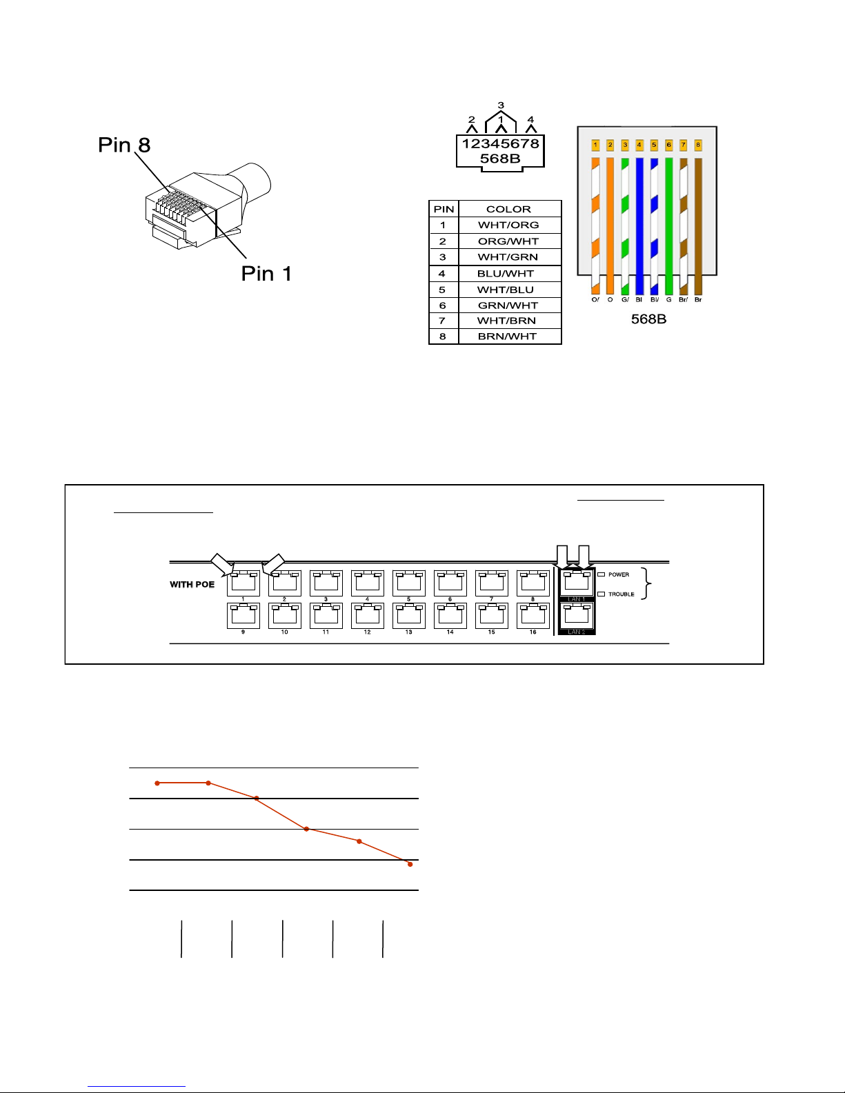
into a single NIC of a NVR unit. The ER8500U has special LED indicators to inform you if there are network loops. If the
Trouble LED is flashing slowly it will indicate that the network has a loop in it and data is cascading. It is recommending to
remove the LAN jack if this occurs and try to locate the physical loop if this problem occur.
Upon power up the devices will undergo initialization and auto-configuration processes (see LED Indicator chart on pg.#7)
which may take a number of seconds (time variations are device/installation/topology parameter dependent) to complete
before PoE and Ethernet communication commences. For optimal performance referring to the PoE/distance chart and ad-
hering to the IP camera/PD operational specifications is recommended. If issues arise during the installation process please
see the “Trouble Shooting Tips” section. You may also contact our web based live tech support at: www.nitek.net or call 1-
(800)528-4343 in order to speak with one of our engineers directly.
The diagram below shows a common network topology.

Simplified System Hookup Diagram
Link Cable
Up to 2000 feet /
Transmitter-end Installation
ET1500U Units
At the camera location securely mount the transmitter.
Find the Link cable from the head-end and make sure it is properly terminated. Connect Link cable to the “Link Port”
of the transmitter. If the head-end unit is powered up it will sense the connection to the transmitter and turn on the
power. This will be indicated by the green POWER LED on the “Network Port”. After about 15 to 30 seconds the
orange 10/100Mb LED on the “Link Port” will turn-on to tell you that the system is connected. An Ethernet device
does not need to be connected for the transmitter to communicate with the head-end.
Finally, connect an Ethernet device to the transmitters “Network Port”. If the device requires PoE power, the POE
OUT, green LED on the “Link Port” will turn on followed by the LINK STATUS LED on the “Network Port”. The IP
camera or other Ethernet device should now be ready to operate. Continue installing the remaining transmitters as
needed.
IP Camera
Cable from
Head-end
Transmitter Hookup Diagram
Link Port
Network Port
LED INDICATORS
Connect-
or LED OFF ON FLASHING
Network
Port
Power No power Power
Good
Link
Status
No Ether-
net
Link
Ethernet Link
Good
Link
Port
PoE Out No PoE
Power Out
PoE Power
Good
10/100 No Link 100Mb 10Mb

IP Camera
Cable from
Head-end
48VDC Powered Transmitter Hookup Diagram
Link Port
Network
Port
115 VAC
Optional
48VDC
Supply
Optional Hookup for High Power PoE Devices
ET1500U Units
In some cases the PoE device connected to the transmitter needs more power than can be supported over a long
cable run. You can usually identify these cases by watching the POWER LED of the transmitter, located on the
“Network Port”. If the power light cycles ON for less then 1 second and then is off for 3 or 4 seconds when the PoE
device is connected, but it turns ON and operates normally without a PoE device connected, this would indicate you
are having a current limit problem.
You should first check the power requirements of the PoE device. Also check the length of the Link cable from head
-end to transmitter. The POE POWER CHART on the previous page will indicate the maximum power available for
your length of cable.
If the needed level of power is not available for the length of cable, used alternate options are available. One meth-
od is to directly power the transmitter with a 48VDC power supply as shown below (Nitek# PS48). When powered
directly from a 48VDC supply the transmitter can deliver full 802.3AT power regardless of the cable length plus an
additional length of up to 100 meters of network cable.
Transmitter used as
PoE Injector*
Distance from
Network Port
PoE Device Power
Available
30ft/10m 33 watts
325ft/100m 26 watts
*Results with 48VDC power to the
Transmitter optional Power Port

Unit Dimensions
Top View
Front View
Rear View
Left Side
Right Side
17.125
17.125
1 2 3 4 5 6 7 8
NITEK
ETHERSTRETCH
12.00
ER16500U UTP RECEIVER WITH POE
LAN 1
POWER
TROUBLE

Connectivity LED Status
Front Panel LED Display
PoE OUT
Network Connection
Green = 100Mb
Orange = 10Mb
Network Connection
Green = 1Gb
YellowYellowYellow = 100Mb
Orange = 10Mb
Power = Green
Trouble = Orange
568B Pinout Termination
Trouble LED
Solid= Temperature Alarm
Flashing= Network Loop Warning
PoE Distance Chart
* Results charted were calculated using four pair 24awg Cat5e cabling
27.4 27.4 25.0
20.0
18.0
30.0
25.0
20.0
15.0
10.0
5.0 500
Meters
400 Meters
1,300 Feet
300 Meters
1,000 Feet
200 Meters
650 Feet
100 Meters
328 Feet
27.4 Was 27.4 Was 25.0 Was 20.0 Was 18.0 Was
Was
14.1
600 Meters
1,960 Feet
14.1 Was

Receiver Unit
Network Output (LAN) Port 1x RJ45 Connector @ 1 Gigabit
Link Port 8x RJ45 Jacks @ 100Mbps each
Ethernet 100BASE-TX Full Duplex per port
Ethernet Connection [8] Auto Configuring 10 ⁄ 100 RJ45 ports
LED Connectivity Indicators Link Status, Power, PoE Out, 10Mb or 100mb
Device Dimensions 1 RU x 12.0"D
Mounting Standard rack mounting design
Operating Temperature 0° to 52° C / 32° to 125° F
Humidity Up to 95% non-condensing
Power Requirements IEC380 power connector - 115/230VAC 50/60Hz
Total Power Output 320 Watts
PoE Capabilities IEEE 802.3af & IEEE 802.3at compliance per port
Max Operating Distance 600m/1,960ft
Shipping Weight 12 lbs
Troubleshooting
PROBLEM POSSIBLE CAUSE
No video/data Check camera and ER8500/ET1500 device connections.
Check UTP cable condition and RJ45 connector terminations.
Check that the camera is powered.
Check that supplied camera power meets manufacturer’s
specifications.
Check cable that cable distances do not exceed PoE capabilities.
Check that UTP cable length does not exceed the operating distances
of the ER8500 & ET1500.
Check link & device status LEDs.
Video/data loss Check network switch terminations & link status.
Check network routing table.
Confer with site Network Administrator
For Tech Support Call 1-(800)528-4343
Technical Specifications

Product Warranty and Return Information
Return Policy
A. All returns for warranty, repair, credit or any other reason must be pre-authorized. A return mer-
chandise authorization (RMA) form must be requested from the NITEK Customer Service De-
partment. The form, which will be emailed to the customer, must be filed out completely and
emailed back to the sender at NITEK for approval. An RMA number will be assigned if the re-
quest is approved. In any event, the customer will be notified by NITEK customer service of the
outcome. All approved returns must be shipped freight prepaid, insured and properly packaged.
A copy of the approved RMA form must be enclosed in the shipping container with the goods
being returned and the RMA number must be marked in a visible area on the exterior of the
container.
B. Credit Returns must have been purchased within the last 30 days of the date of the receipt
of the equipment at NITEK. Credit returns must be current products listed on the NITEK
published price list, in effect at the time of the return and must be in new and saleable con-
dition, with all factory packaging. All Credit returns are subject to a restocking charge of up
to 40%. Additional restocking and/or refurbishing charges may be assessed upon inspec-
tion. If it is determined by NITEK that the returned equipment does not meet these condi-
tions, a credit will not be issued.
Lifetime Limited Warranty
Network Extender Products
NITEK warrants the original consumer purchaser that the Network Extender products that it sells
will be free from defects in material and workmanship. If any such product proves defective by our
inspection, after sale to the original consumer purchaser, NITEK, at its option, will either repair the
defective product without charge for parts and labor or will provide a replacement in exchange for
the defective product.
In order to obtain service under this warranty, the customer must notify NITEK of the defect and
shall be responsible for packaging and shipping the defective product to the service location des-
ignated by NITEK with shipping charges prepaid. NITEK shall pay for the return of the product to
the purchaser if the shipment is to a location within the U.S.A. The purchaser shall be responsible
for paying all shipping charges, duties and taxes if the product is returned from a location outside
the U.S.A.
This warranty shall not apply to any defect, failure or damage caused by improper use or improper
or inadequate maintenance or care, or to any product which shall have been repaired or altered
outside our plant in any way, or which has been operated in a manner exceeding its specifica-
tions, or which has had the serial number removed. NITEK shall not be obligated to furnish service
under this warranty: a) to repair damage resulting from attempts by personnel other than NITEK
representatives to repair or service the product; b) to repair damage resulting from improper use
or connection to incompatible equipment; or c) to service a product that has been modified or inte-
grated with other products when the effect of such modification or integration increases the time or
difficulty of servicing the product.
This warranty is given by NITEK with respect to the Network Extender products in lieu of any other
warranties, express or implied. NITEK disclaims any implied warranties of merchantability or fit-
ness for a particular purpose. NITEK’s responsibility to repair or replace a defective product is the
sole exclusive remedy provided to the purchaser for breach of this warranty. NITEK will not be
liable for any indirect, incidental or consequential damages irrespective of whether NITEK has ad-
vance notice of the possibility of such damages.
Other manuals for ER8500U
1
Table of contents
Other Nitek Extender manuals

Nitek
Nitek EE328 User manual

Nitek
Nitek ET1500UW User manual

Nitek
Nitek VR448COAX User manual

Nitek
Nitek VR148UTP User manual

Nitek
Nitek EL4500U User manual

Nitek
Nitek VR148COAX User manual

Nitek
Nitek ER1651U User manual

Nitek
Nitek ER8400C User manual

Nitek
Nitek Etherstretch EL1500CW User manual

Nitek
Nitek ER8400U User manual