Nitek ER1651U User manual
INSTALLATION GUIDE
NITEK®
De Schans 19-21 2a
8231 KA Lelystad
Tel: +31(0)320-230005
WWW.NITEK.NL
USA
5410 Newport Drive, # 24
Rolling Meadows, IL 60008
Phone: (847) 259-8900
Fax: (847) 259-1300
WWW.NITEK.NET
EUROPE
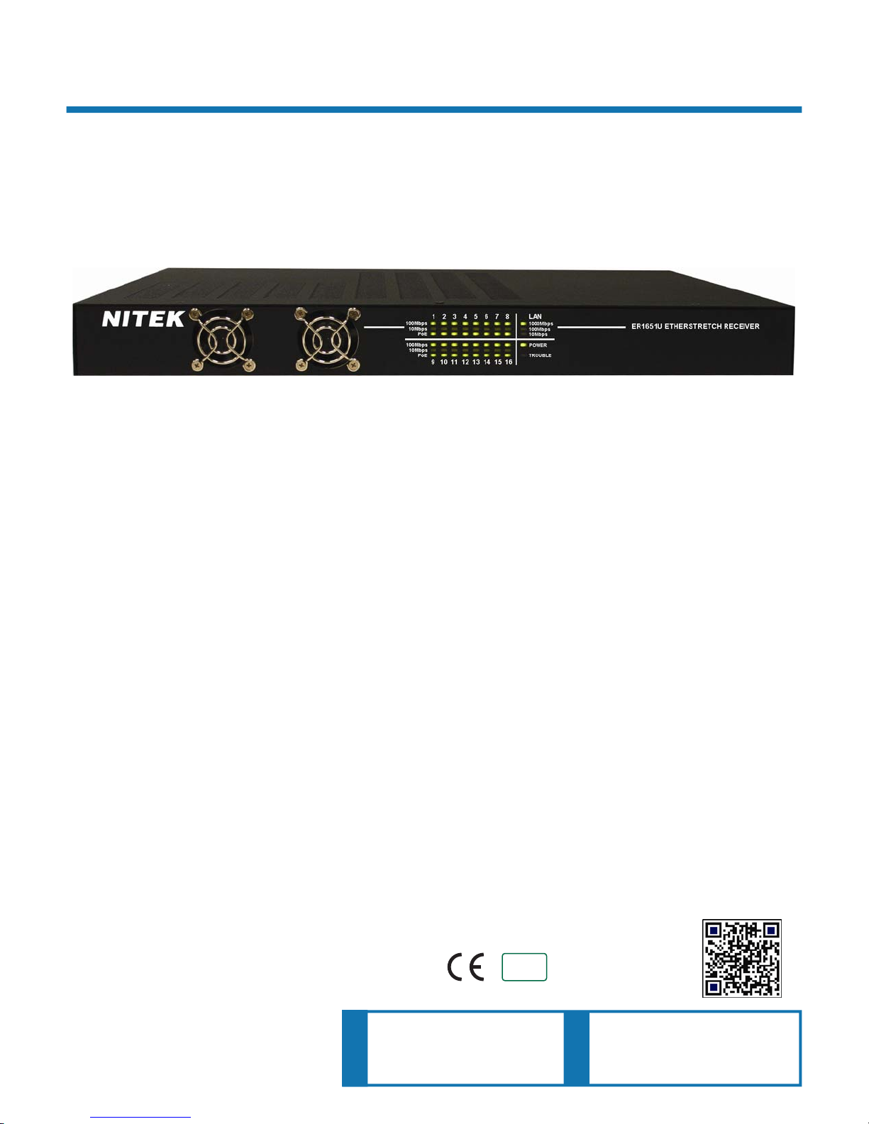
ER1651U
The ER1651U is another component of the NITEK cutting edge EtherStretch line. Our EtherStretch solution al-
lows for the utilization of existing twisted pair cable infrastructure to transmit data from IP cameras and other net-
work devices over the given copper media well beyond the 100 meter or 328 feet networking distance limitation.
The ER1651U is a Ethernet extending rack mounted sixteen port receiver unit with built-in Gigabit switching capa-
bilities. The unit requires very little installation time and absolutely no set up or configuration. Independently the
ER1651U will work as a fully functional Layer 2 switch. Additionally, the ER1651U and associated ET1551U trans-
mitters (up to 16) can quickly turn ordinary Twisted Pairs into a series of high speed network communication path-
ways. When used with remotely powered ET1551U transmitters, the system will allow for cable runs of up to
500m/1600ft supplying both a network connection and PoE power.
The ER1651U is completely transparent to the network thus requiring no IP or MAC addressing. Simply connect
your network devices to the transmitter network port along with the existing cables to the receiver and the system
quickly begins communicating. LED indicators show the status and data speed of network communications along
with Power and Trouble confirmation.
NITEK EtherStretch ER1651U reliably extends network communications to overcome cable distance limitations
offering connectivity to devices in locations traditional networking does not allow. The ER1651U is ideal for retro-
fitting existing installations. The rack mounted unit is robustly constructed of molded steel casing with appropriate
built-in cooling and ventilation.
Description
16 Port IP Video Extender Over Single Twisted Pair
With Built-In Gigabit Layer 2 Switch with EtherStretch
03262013
RoHS
COMPLIANT
2002/95/EC

Important Safety Instructions
Read all Safety Instructions.
Keep the Instructions for future reference.
Be sure to HEED all Warnings.
Follow ALL instructions.
DO NOT use this device or any of the equipment described, near water.
Clean this device ONLY with a dry cloth.
DO NOT block any ventilation openings.
Install in accordance with the manufacturer’s instructions.
DO NOT install near any heat sources such as radiators, heat registers, stoves or other apparatus (including
amplifiers) that produce heat.
DO NOT defeat the safety purposes of polarized or grounding type plugs. A polarized plug has two blades, with
one blade wider than the other. A grounding plug has two blades and has a third grounding prong. The wide
blade and the grounding prong are provided for your safety. If the provided plug does not fit into your outlet,
consult an electrician for replacement of the obsolete outlet.
DO NOT connect the unit to an electrical supply if the wiring or over current protection of the supply could be
overloaded when the ratings listed on the unit are considered.
Protect the power cord from being walked on or pinched especially at plugs, convenience receptacles and other
points where they exit from the device.
Only use attachments and/or accessories specified by the manufacturer.
Refer all servicing to qualified service personnel. Servicing is required when the device has been damaged in any
way, such as the power supply cord or plug is damaged, liquid has been spilled on, or objects have fallen into the
device, the device has been exposed to rain or moisture, does not operate normally or has been dropped.
WARNING: To reduce risk of fire or electric shock, do not expose this apparatus to rain or moisture.
Installation shall be performed ONLY by qualified personnel and must conform to all local codes.
Unless the device is specifically marked as a NEMA 3, 3R, 3S, 4, 4X, 6 or 6P enclosure, it is designed for indoor
use ONLY and it must not be installed where exposed to rain or moisture.

Parts of the ER1651U (Front Panel)
Installation Considerations
Wire and Cable Recommendations: The ER1651U is designed for use with up to sixteen (16) Pairs
of Twisted Wire, compatible with all Category cabling (Cat3, Cat5, Cat5e and Cat6). The quality of
which must be consistent with any reasonably serviceable cable condition. That is free from damage
as in cuts, breaks, or cracks to the outer covering and insulated shielding which may compromise the
signal conductivity of the cable.
For more specific information regarding wire types, gauges, and proper installation techniques please
call Tech Support at 1-(800)528-4343 USA or (847)259-8900 (outside US).
Ethernet & PoE: The ER1651U is designed to receive up to 100Mbps (per transmitter) of Ethernet
data and transmit up to 1 Gigabit of aggregate LAN traffic. Additionally, the ER1651U provides per
port sourcing power to operate the transmitter (ET1551U). The transmitter, using the optional power
input can support both 15.4W (802.3af) and 25.5W (802.3at) power schemes at a maximum distance
of 1,600ft./500m. Before considering this solution be sure that the cable involved does not exceed
the recommended maximum lengths. If the cable length is indeterminate at the time of installation,
we recommend the use of a time domain reflectometer (TDR) or other method to determine length of
unknown cable distance estimates.
12345678
9 10111213141516
LAN
100 Mbps
10 Mbps
1000 Mbps
100 Mbps
10 Mbps
POWER
TROUBLE
100 Mbps
10 Mbps
PORT PWR
PORT PWR
ER1651U ETHERSTRETCH RECEIVER
NITEK
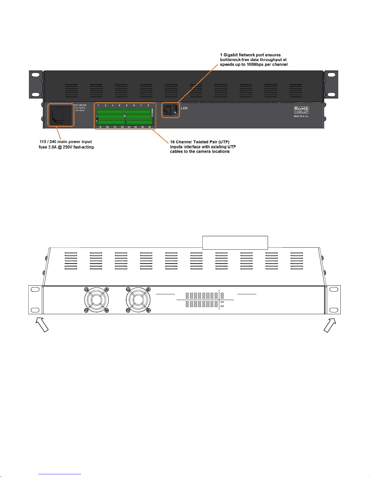
Parts of the ER1651U (Rear Panel)
Device Mounting Options
The ER1651U is to be rack mounted. Use the included mounting ears when rack mounting the unit, and be sure to
follow these guide lines.
a. Operating Ambient - Do not install the unit in an assembly where the ambient temperature could exceed
52°C (125°F). NOTE: the ambient temperature in a closed or multi-unit rack assembly could greatly exceed
the ambient temperature outside that assembly.
b. Air-Flow – Leave space on the front of the unit for airflow into the cooling fans and some space on top of the
unit for air to exit the unit. Adequate air flow is required for safe operation.
c. Mechanical Loading – The mounting ears were designed for two ears to support one unit. Other
configurations, such as mounting other equipment directly on top of the unit or using only one mounting ear,
could cause a hazardous condition due to uneven or excessive mechanical loading.
NOTE: Use all four mounting screws to properly secure the unit to the rack.
Mounting
Ears
Front
Back
Mounting
Ears
Rack Mounting

Installation & Setup
Equipment Requirements & Mounting: The process for employing the ER1651U is rather quick and simple. A
common topology involves up to sixteen (16) existing Twisted Pair cables up to 500m/1,600ft, up to sixteen (16)
ET1551U transmitters, up to sixteen (16) IP cameras or other peripheral network devices. The ET1551U transmit-
ter is both 802.3af and 802.3at compliant, in conjunction with a PS48 power supply. That is it produces 15.4W of
802.3af as well as 25.4W of 802.3at PoE+ power for proper attached device operation.
The method for facilitating Ethernet communication over twisted pair cable starts with connecting the ER1651U
with up to sixteen (16) twisted wire pairs via the four plug-in terminal blocks. The IP camera / PD establish connec-
tivity to ET1551U via RJ45 jacks and a CAT5e/CAT6 patch cords. The ER1651U powers itself and all attached
ET1551U transmitters, providing that the IP devices are self powered. In case of the IP device not having its’ own
power source, a PS48 power supply must accompany the corresponding ET1551U transmitter. The IP data from
the PD is transmitted from the ET1551U over each individual Twisted Pair cable to the rack mounted ER1651U.
The aggregate PD data is transmitted to the greater LAN or WAN via the gigabit LAN port labeled and located on
the back of the NITEK PSE. The ER1651U is a Layer 2 switch and with 1 “smart” LAN port. If the Trouble LED is
flashing slowly it will indicate that the network has a loop in it and data is cascading.
Upon power up the devices will undergo initialization and auto-configuration processes (also see LED Indicator
chart on page 7) which may take a number of seconds (time variations are device/installation/topology parameter
dependent) to complete before PoE and Ethernet communication commences. For optimal performance referring
to the PoE/distance chart and adhering to the IP camera/PD operational specifications is recommended. If issues
arise during the installation process please see the “Trouble Shooting Tips” section. You may also contact our web
based live tech support at: www.nitek.net or call 1-(800)528-4343 USA or 1-(847)259-8900 (other) in order to
speak with one of our engineers directly.
The diagram below shows a common network topology.
Installment Topology
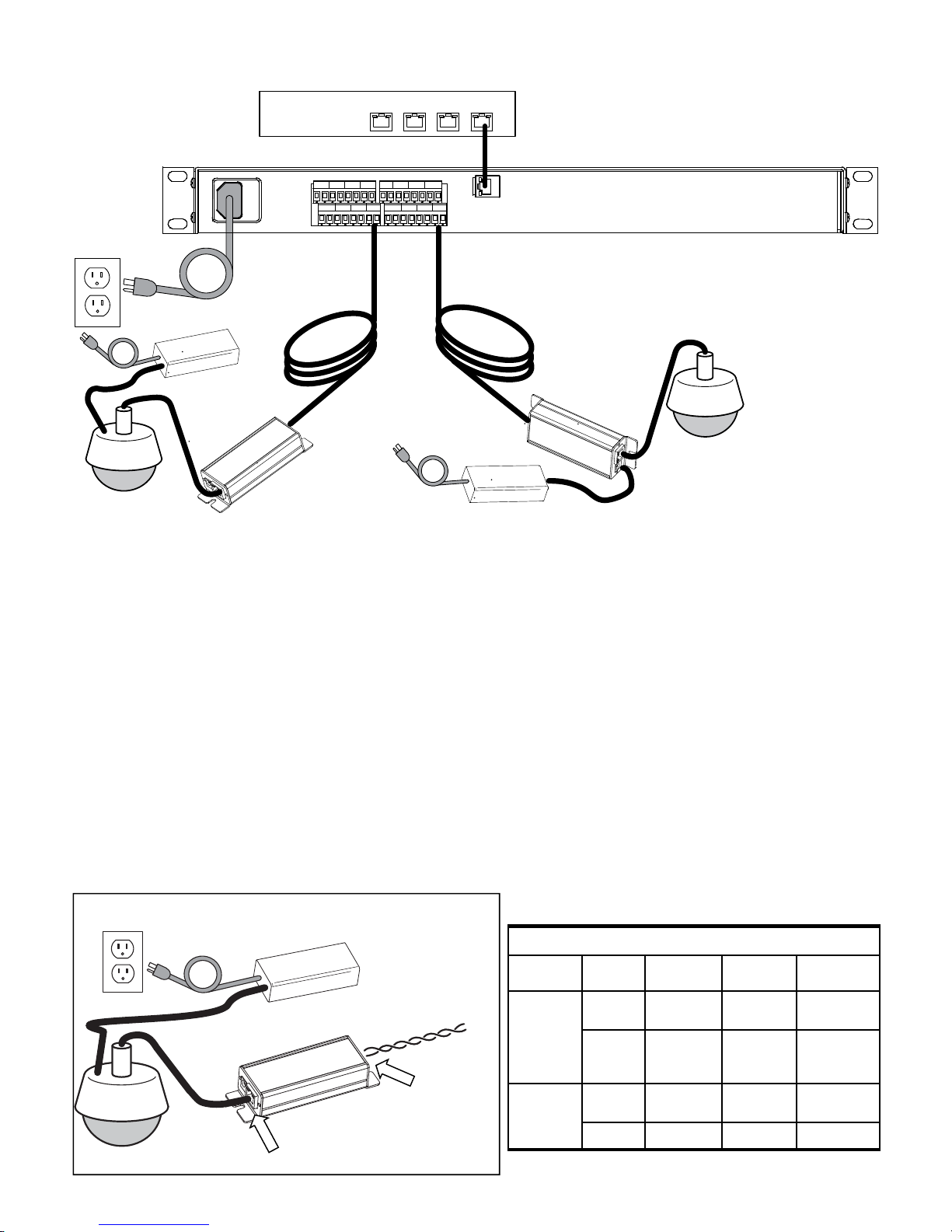
ET1551U
ET1551U
PowerSupply
NITEK PS48
Network Switch,
NVRor Server
LAN
115/230
VAC
ET1551U
Power Supply
At the camera location securely mount the transmitter.
Find the twisted pair cable from the head-end and make sure it is properly terminated. Connect the wires of the
twisted pair cable to the “Link Port” of the transmitter, beware of the polarity of the connection. If the Head-end unit
is powered up it will sense the connection to the transmitter unit and turn on the power. This will be indicated by the
green POWER LED on the “Network Port”. After several minutes the green 10/100 (upper) LED at the “Link Port”
will turn-on to tell you that the Head-end has connected with the transmitter unit. The camera does not need to be
connected for the transmitter to communicate with the Head-end.
Finally, connect a camera or other Ethernet device to the transmitter “Network Port”. The IP camera or other
Ethernet device should now be ready to operate. If the camera needs PoE power please refer to the next section for
how to power the ET1551 when PoE power is needed. Otherwise continue installing the remaining transmitters as
needed.
Note: The Head-end unit is only designed to supply power for the ET1551U transmitter unit. While some
cameras at short distances may operate with PoE form the head-end unit, it maybe insufficient for
Transmitter Hookup Diagram
Connector LED OFF ON FLASHING
Network
Port
Power No power Power
Good
Link
Status No Ethernet
Link
Ethernet
Link
Good
Link
Port
PoE Out No PoE
Power Out PoE Power
Good
10/100 No Link 100Mb 10Mb
LED INDICATORS
Simplified System Hookup Diagram
Transmitter-end Installation
ET1551U Units System
IP Camera
IP Camera
Twisted Pair from
Head-end
Link Port
Network Port
IP Camera
Network Switch,
NVR or Server
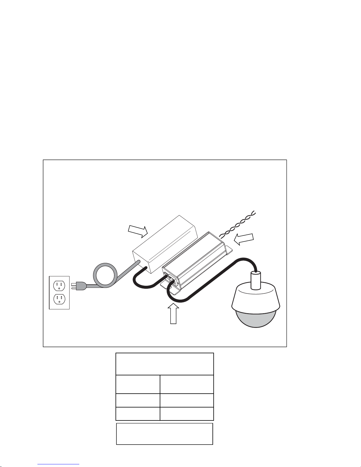
Optional Hookup for High Power PoE Devices
ET1551U Units
Note: This installation is for connecting to devices that do not have their own separate power supply and
need to be powered via PoE.
In some cases the PoE device connected at the transmitter end needs more power than can be supported over a
long Twisted Pair run. You can usually identify these cases by watching the POWER LED of the transmitter, located
on the “Network Port”. If the power light cycles ON for less then 1 second and then is off for 3 or 4 seconds when
the PoE device is connected, but it turns ON and operates normally without a PoE device connected, this would
indicate you are having a current limit problem.
At the camera location securely mount the ET1551 transmitter. The ET1551 can provide full 802.3at power to oper-
ate most IP cameras and other PoE devices, when powered directly from a 48VDC supply. Either use the PS48
Power Supply from Nitek or other 48VDC power supply to operate the units. The illustration below shows the use of
the PS48 supply. Other DC power supplies can be used with the supplied power connector if desired but must be
48 to 56 VDC for proper operation.
Distance from
Network Port PoE Device Power
Available
30ft/10m 33 watts
325ft/100m 26 watts
Transmitter used as
PoE Injector*
*Results with 48VDC power to the
Transmitter optional Power Port
48VDC Powered Transmitter Hookup Diagram
PS48
ET1551
Twisted Pair from
Head-end
Link
Port
IP Camera
Network
Port
115 VAC
Optional
48VDC
Supply
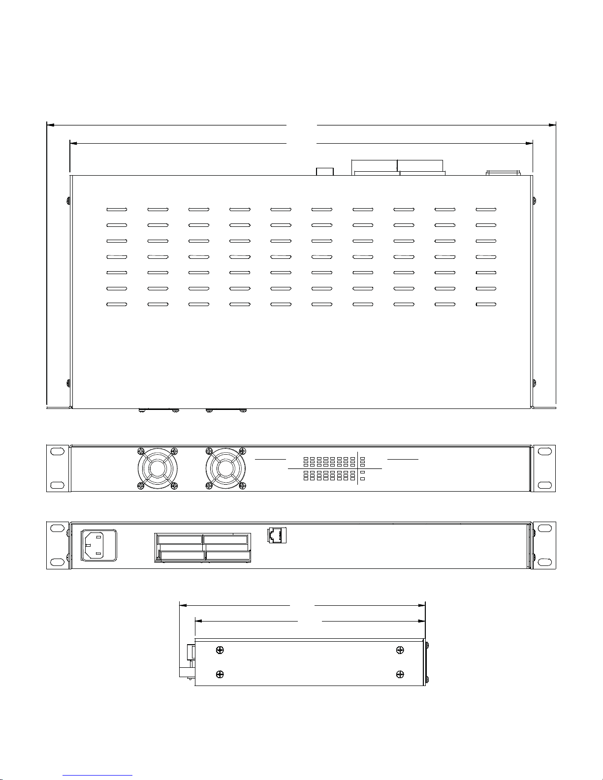
Unit Dimensions
12345678
9 10111213141516
LAN
100 Mbps
10 Mbps
1000 Mbps
100 Mbps
10 Mbps
POWER
TROUBLE
100 Mbps
10 Mbps
PORT PWR
PORT PWR
ER1651U ETHERSTRETCH RECEIVER
NITEK
19.0
17.3
9.2
8.6
Top View
Front View
Rear View
Left Side

Connectivity LED Status
8 Position Degson Wire Termination
Trouble LED
Solid= Temperature Alarm
Flashing= Network Loop Warning
1234
+ - + - + - + -
568B Pinout Termination
TCP/IP
3
TCP/IP
4
TCP/IP
2
TCP/IP
1
+ -+ -+ -+ -
+ -+ -+ -+ -+ -+ -+ -+ -
+ -+ -+ -
+ -
1234 5678
910
11 12 13 14 15 16
ER1651U 16 Channel Ports

Troubleshooting
Technical Specifications
Receiver Unit
Network Output (LAN) Port 1x RJ45 Connectors @ 1 Gigabit
Link Port 16 Twisted Pair Terminals
Ethernet 16x 100BASE-TX Full Duplex per Twisted Pair Terminals
LED Connectivity Indicators Link Status, Power, PoE Out, 10Mb or 1000Mb
Power Requirements IEC380 power connector - 115/230VAC/50/60Hz/150Watt Max
Total Power Output 52Vdc @ 125 watts max
Max Operating Distance 500m/1,600ft
UTP Cable Specifications
DC Loop Resistance 51 Ohms/1000 feet (max) (51 Ohms/304 meters)
Normal Capacitance 17pF/ft.
Impedance 100 Ohms +/- 20%
UTP Category 2 or better
Operating Temperature -15° to 75° C / 0° to 167° F
Humidity Up to 95% non-condensing
Mounting Dimensions Standard rack mounting design 1RU x 9.0”D
Shipping Dimensions 18”W x 24”H x 8.5”D
Shipping Weight 11 lbs
PROBLEM POSSIBLE CAUSE
No video/data Check camera and ER1651U/ET1551U device connections.
Check Twisted Pair wire condition and connector terminations.
Check that the camera is powered.
Check that supplied camera power meets manufacturer’s
specifications.
Check cable that cable distances do not exceed PoE capabilities.
Check that UTP cable lengths does not exceed the operating
distances of the ER1651U & ET1551U.
Check link & device status LED.
Video/data loss Check network switch terminations & link status.
Check network routing table.
Confer with site Network Administrator
For Tech Support Call 1-(800)528-4343 (USA)
1-(847)259-8900 (Other)
www.nitek.net (web)

Product Warranty and Return Information
Return Policy
A. All returns for warranty, repair, credit or any other reason must be pre-authorized. A return mer-
chandise authorization (RMA) form must be requested from the NITEK Customer Service De-
partment. The form, which will be emailed to the customer, must be filed out completely and
emailed back to the sender at NITEK for approval. An RMA number will be assigned if the re-
quest is approved. In any event, the customer will be notified by NITEK customer service of the
outcome. All approved returns must be shipped freight prepaid, insured and properly packaged.
A copy of the approved RMA form must be enclosed in the shipping container with the goods
being returned and the RMA number must be marked in a visible area on the exterior of the
container.
B. Credit Returns must have been purchased within the last 30 days of the date of the receipt
of the equipment at NITEK. Credit returns must be current products listed on the NITEK
published price list, in effect at the time of the return and must be in new and saleable con-
dition, with all factory packaging. All Credit returns are subject to a restocking charge of up
to 40%. Additional restocking and/or refurbishing charges may be assessed upon inspec-
tion. If it is determined by NITEK that the returned equipment does not meet these condi-
tions, a credit will not be issued.
Limited Warranty
Network Extender Products
NITEK warrants the original consumer purchaser that the Network Extender products that it sells
will be free from defects in material and workmanship for a period of two years from date of pur-
chase. If any such product proves defective by our inspection, after sale to the original consumer
purchaser, NITEK, at its option, will either repair the defective product without charge for parts and
labor or will provide a replacement in exchange for the defective product.
In order to obtain service under this warranty, the customer must notify NITEK of the defect before
expiration of the warranty period. The customer shall be responsible for packaging and shipping
the defective product to the service location designated by NITEK with shipping charges prepaid.
NITEK shall pay for the return of the product to the purchaser if the shipment is to a location within
the U.S.A. The purchaser shall be responsible for paying all shipping charges, duties and taxes if
the product is returned from a location outside the U.S.A.
This warranty shall not apply to any defect, failure or damage caused by improper use or improper
or inadequate maintenance or care, or to any product which shall have been repaired or altered
outside our plant in any way, or which has been operated in a manner exceeding its specifica-
tions, or which has had the serial number removed. NITEK shall not be obligated to furnish service
under this warranty: a) to repair damage resulting from attempts by personnel other than NITEK
representatives to repair or service the product; b) to repair damage resulting from improper use
or connection to incompatible equipment; or c) to service a product that has been modified or inte-
grated with other products when the effect of such modification or integration increases the time or
difficulty of servicing the product.
This warranty is given by NITEK with respect to the Network Extender products in lieu of any other
warranties, express or implied. NITEK disclaims any implied warranties of merchantability or fit-
ness for a particular purpose. NITEK’s responsibility to repair or replace a defective product is the
sole exclusive remedy provided to the purchaser for breach of this warranty. NITEK will not be
liable for any indirect, incidental or consequential damages irrespective of whether NITEK has ad-
vance notice of the possibility of such damages.
Table of contents
Other Nitek Extender manuals

Nitek
Nitek ET1500UW User manual

Nitek
Nitek Etherstretch EL1500CW User manual

Nitek
Nitek EtherStretch ER8500C User manual

Nitek
Nitek VR148UTP User manual

Nitek
Nitek EE328 User manual

Nitek
Nitek ER8500U User manual

Nitek
Nitek ER8400U User manual

Nitek
Nitek VR148COAX User manual

Nitek
Nitek ER8400C User manual

Nitek
Nitek VR448COAX User manual


