niu N-GT User manual

V1.0.0
1
N-GT Scooter
Dual batteries + Fast Charger
Service Manual
e13*168/2013*00546*00
Jiangsu Niu Electric Technology Co. Ltd

V1.0.0
2
Foreword
Key points in maintenance of Niu NGT are described in this maintenance manual.
Preparations in the maintenance manual include notes to all operations. Please read the manual
carefully before operating.
Key points in the inspection and adjustment, includingmaintenance methods for scooter safety and
component performance that are applied from regular examinations, are described.
Chapters are edited with disassembly diagrams, system figures and instructions about the
maintenance and failurediagnosis.
Note:
Modifications of scooter version or structure as well as photos, pictures or instructions in the manual
are referred to physical objects without further notice.
Maintenance Information
The maintenance and reparation information contained in this manual is for technical specialists only.
Maintenance or reparation performed by those who are not trained properly and provided with
appropriate tools and equipment may cause injuries to themselves or others and also lead to
damages or unsafe conditions of the scooter.
The proper maintenance and reparation procedures, some of which require special tools and
equipment, are described in this manual. The risks in terms of personal safety and scooter operation
safety, which may be resulted from the use of components, maintenance procedures or tools not
recommended by Niu must be verified.
Please make replacement with original electric components made by Niu or equivalents that have
corresponding part numbers. We strongly recommend you not to use inferior components.
Customer Safety Notice
The proper maintenance is crucial for customer safety and scooter reliability.Any errors or omissions
in scooter maintenance may result in operating malfunctions, scooter damages or injuries.
Improper maintenance or reparation may lead to unsafe conditions under which serious injuries or
even death of your customers or other people may be incurred.
Please carefully follow the procedures and cautions in this manual and other maintenance materials.
Personal Safety Notice
This manual is used only by professional maintenance technicians, and the warning information
about multiple basic workshop safety operation procedures (such as the procedure that requires
gloves when working on hot components) is n=ot set forth herein. We recommend you not to carry
out procedures specified in this manual without readiness if you have not received the workshop
safety trainingor grasped the knowledge about maintenance safety specifications.
The followingare listed as several most importance general notes to maintenance safety. However,
we are unable to set forth the warning for each of risks that may arise from maintenance and
reparation procedures. You have to determine at your discretion whether a detail task should be
implemented.
Failure to properly follow relevant instructions and notes may result in serious injuries or even death.
Please carefully follow procedures and notes in this manual.

V1.0.0
3
Importance Safety Notes
Make sure that you have completely understood basic workshop operation safety procedures and
taken on proper protective clothes and are provided with safety equipment. Extra attention should be
paid to the followingin the implementation of a maintenance task:
•Read all the relevant instructions before operation, and make sure that you have necessary tools,
spare parts, components and skills to implement a maintenance task safely and completely.
•There are high-voltage circuits in the scooter system, which can cause electric shock. It must be
verified that your maintenance site, tools, protective equipment and operation procedures are in
compliance with the insulation requirement.
•Eyes should be protected with proper safety glasses, goggles or masks in operations such as
hammering, drilling, polishing or prying or working around high-pressure air or fluid tanks, springs
or other energy storage components. Eye protection devices should be worn as long as there are
suspicious conditions.
•Other protection devices such as gloves or safety shoes are used where necessary. Gloves should
be worn before handling of a hot or sharp component that may cause serious burns or cuts or
grasping of any things that may cause injuries.
•Measures should be taken to protect you and others once a scooter is lifted. Make sure that the
scooter is always supported stably when being lifted with a crane or jacks. Please use jack mounts.
•The hot motor after driving for a long time may cause burns. Waitfor the motor to cool down
before working on it.
•Moving parts can cause injuries. Make sure that your hands, fingers and clothes are not
obstructive.
•Components must be cleaned with non-flammable solvents instead of the gasoline.
•All components related to a storage battery should be away from cigarettes, sparks and flames.

V1.0.0
4
Contents
Foreword 2
Maintenance Rules and Important notes 5
Cable connector inspection 6
Scooter Identification 7
Specifications 8
Part Names 11
Parts Removal and Installation Procedure 17
Front Wheel 41
Front Fork 43
Steering Handlebar 45
Rear Wheel/ Rear Suspension 47
Brake System 50
Lithium battery/charger 57
BCS and Fast Charger 65
Electrical System
Electronic components 66
Diagnostic Code 110
Regular Maintenance Checklist 130

V1.0.0
5
Maintenance Rules
1. Metric tools should be made as available as possible in the maintenance of the scooter. Use of
improper tools may damage the scooter.
2 Clean off the dirt outside parts or assemblies of the chassis or braking system before guard
removal from the scooter or opening for maintenance.
3 Please clean parts and blow them with an air compressor after removal and before measurement
of the wearing value.
4 Rubber parts that have become aged or deteriorated are very easy to be damaged by the solvent
or oil. They should be checked or replaced if necessary before reassembly.
5. Multiple assemblies should be loosenedin the sequence from outside to inside and beginning with
small ones.
6. Complex assemblies should be stored in a proper installation sequencefor further assembling.
7 Extra attention should be paid to important fitting positions before disassembling. Parts that are no
longer to be used should be replacedbefore disassembly.
8 The bolt or screw length varies with assemblies and guards. Bolts or screws must be installedat
correct positions. A bolt can be placed into a bolt hole for fitness in case of confusion
9 The oil seal should be installed by lubricant applicationinto the oil seal groove, and should be
checked for smoothness, smoothness and damages before installation.
10 The spherical bearings (on the front wheel-hub or rear wheel motor) should be removed by
holding one or two bearing races (the inner and outer races) with tools. The bearing may be
damaged in removal if the force is applied only to one race (the inner or outer race) and thus must be
replaced.
Important notes
1.Please use originalparts made by Niu. Use of components that are not in compliance with design
specificationsby Niu Company may cause damages to the scooter.
2.Maintenance operations can be performed only with metric tools. The metric bolts, nuts and
screws can not be interchanged with British fasteners.
3.The replacement with new washers, O rings, split pins and lock shims should be made for
reassembly.
4.Bolts or nuts should be tightened by beginning with large-diameter bolts or inward bolts and then
gradually tightening to specified torques diagonally, unless otherwise indicated.
5.Clean components that have been removed with the detergent solution.All the sliding faces
should be lubricated before assembling.
6.Check all components for the proper installation and operating after assembly.
7.Remove the dirt and oil stains before measurement. Apply recommended lubricants to sections to
be lubricated during assembly.
8.Apply the lubricant to part surfaces to avoid rusting and dust accumulation, if the engine and
transmission systems need to be stored for a long time after disassembling.

V1.0.0
6
Cable connector inspection
•Loose cables constitute a risk to electric safety. Cables should be checked after their clamping to
ensure electric safety.
•Bending of cable clamps towards welding points is not allowed.
•Cables are bound at designated positions.
•Cable placement at the scooter frame end or a sharp angle is not allowed.
•Cable placement at the bolt or screw end is not allowed.
•Cable placement should be made away from thermal sources or positions where cables may be
stuck in moving.
•The cable placement along stem handles should not be made too tight or loose and should not
interfere with adjacent parts at any steering positions.
•Cables should be placed smoothly without being twisted or tied.
•Verify whether the connector shroud is damaged or the connector is excessively open before
connecting.
•Please protect the cable at a sharp angle or turning position with adhesive tapes or a hose.
•Cables should be bound reliably with adhesive tapes after reparation.
•Controlling cables should not be bent or twisted. The controlling would not be flexible if controlling
cables were damaged.
V1.0.0
7
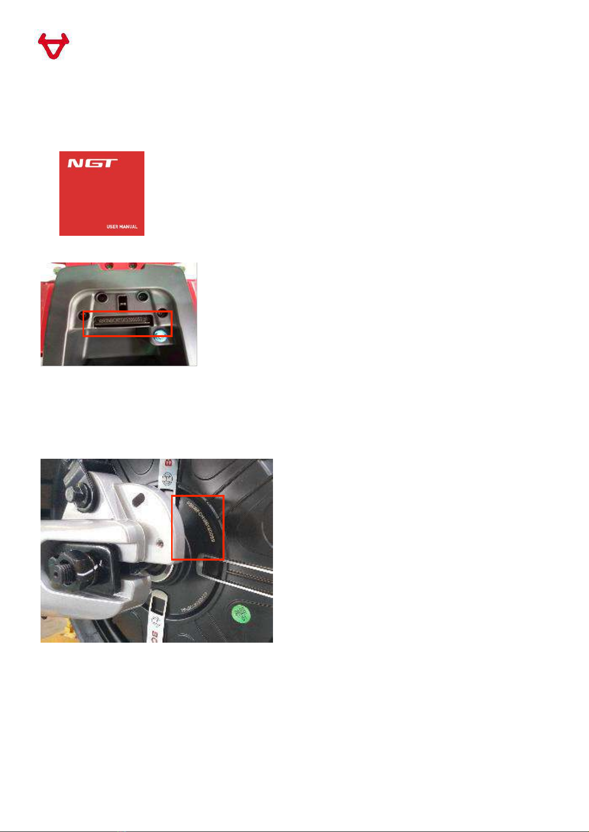
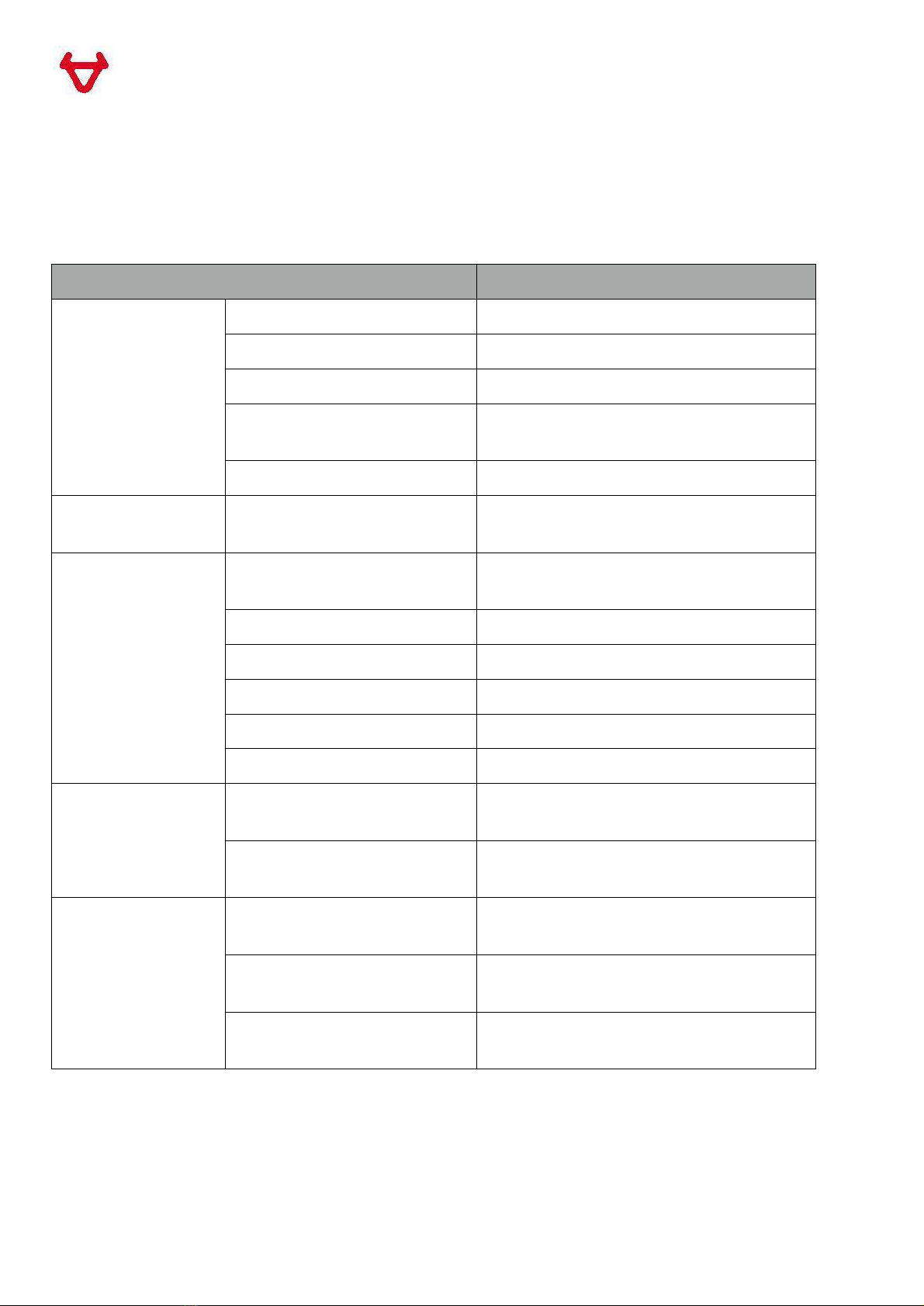
Scooter Identification
•Vehicle serial number (SN) is in the user manual
•The scooter frame identification code (VIN) is made on the rear frame at rear seat cask.
The motor code is made at left side of the wheel-hub motor.
V1.0.0
8
Overall specifications:
EU approval number: e13*168/2013*00546*00
Item Specifications
Dimensions
Length ×width ×height 1815×725×1185 mm
Wheelbase 1290mm
Complete vehicle kerb mass 90Kg
Ground clearance of the
seat cushion 740mm
Ground clearance 140mm
Scooter frame Type of the scooter frame The pedal type made with combined
welding of panels and pipes
Specifications of the front
tire 90/90-12 44J
Type of the front rim MT2.15X12 aluminum alloy
Air pressure of the front tire 200KPa
Specification of the rear tire 120/70-12 56J
Type of the rear wheel MT3.50X12 wheel-hub motor
Air pressure of the rear tire 225KPa
Suspension
Front shock absorber Telescopic type with 31mm dual
hydraulics
Rear shock absorber Telescopic type with dual hydraulic
springs
Brake
Type of the front brake Single sided hydraulic brake with dual
pistons
Type of the rear brake Opposed sided hydraulic brake with
dual pistons
CBS Division of brake force: Front: 30%
Rear: 70%
V1.0.0
9
Specifications of the motor controller system
Item Specifications
Motor
Motor type Brushless permanent-magnet motor
Controller type FOC vector control
Rated voltage DC60V
Rated power 3000W
Maximum motor power 3500W at 639min-1
Maximum motor torque 52N.M at 630min-1
Controller
Rated voltage DC60V
Rated output power 2500W
Maximum input current 70A
Maximum output current 280A
Specifications of the battery/charger
Item Specifications
Propulsion Battery
Type Packed lithium battery
Number of Cells 2*(17*10)=340(2 in parallel)
Rated voltage 60V DC
Rated capacity 2*35Ah
Mass 2*11KG=22KG
Environmental Propulsion
Performance Energy Consumption 35Wh/KM
Electric Range 134KM
Fast Charger Output voltage 35-84V DC
Max Output current 12A

V1.0.0
10
Specifications of the braking system
Item Standard value (mm) Minimum Thickness(mm)
Diameter of the front brake disc φ220mm -
Thickness of the front brake disc 4.0 3.0
Thickness of the front brake pad 4.0 3.0
brake fluid DOT3 or DOT4
Diameter of the rear brake disc φ180mm -
Thickness of the rear brake disc 3.5 2.5
Thickness of the rear brake pad 4.5 3.0
brake fluid DOT3 or DOT4
Specifications of the Lighting/Display/switch
Electric system
Item Specifications
Front headlight 12V LED
Turn signal lamp 12V LED
Rear tail lamp 12V LED
Brake lamp 12V LED
Display 12V LCD display
Central control unit(ECU) 12V
USB charging interface 5V
V1.0.0
11
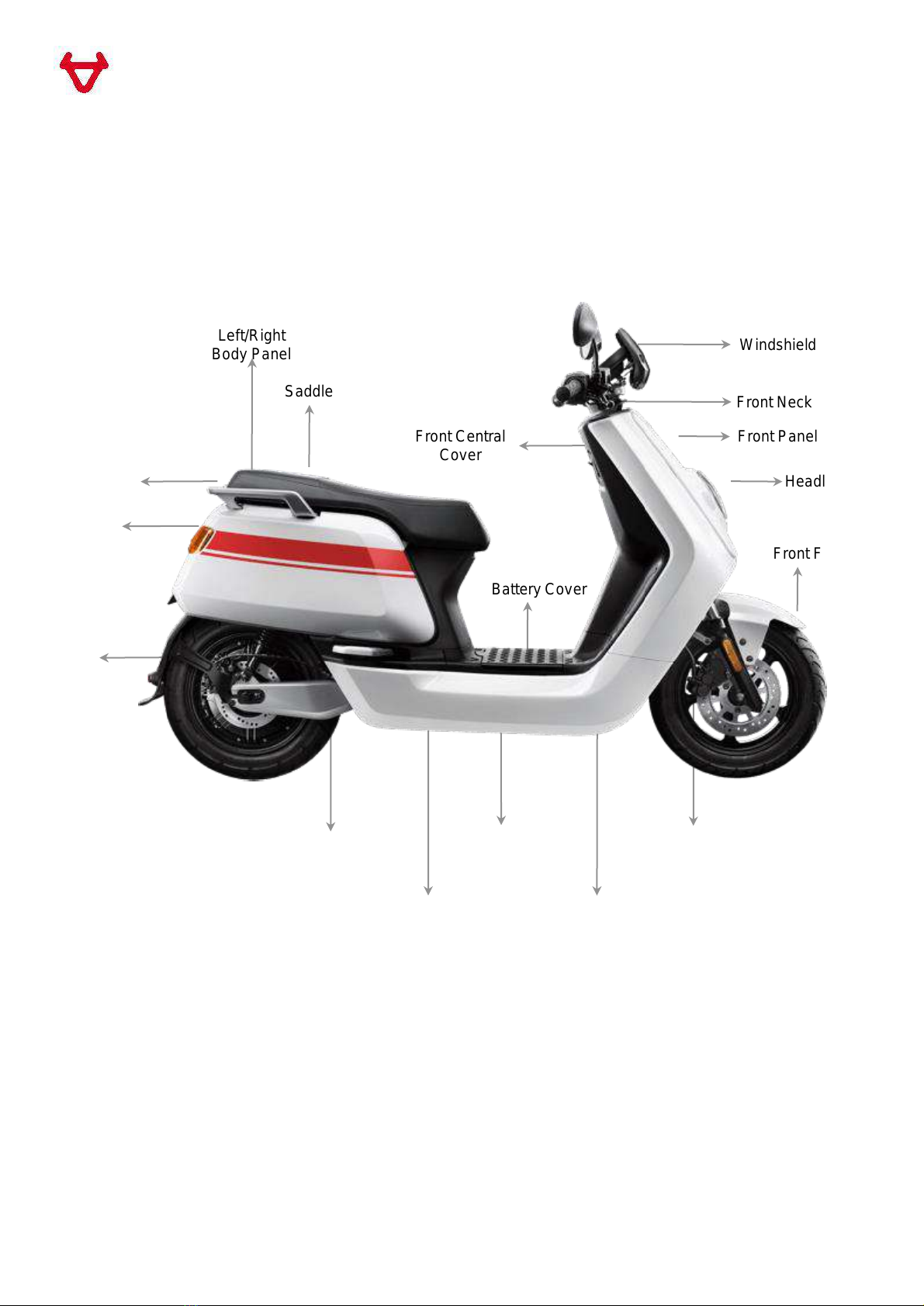
Part Names
Scooter body
Windshield
Front Neck Cover
Front Panel
Front Fender
Front Left/Right
Panel
Left/RightSide
Panel
Left/RightCentral
Cover
Rear
Fender
Rear
Left/Right
Handrail
Saddle
Front Central
Cover
Rear Central
Cover
Left/Right
Body Panel
Battery Cover
Footrest
Headlight
Tail light

V1.0.0
12
Parts Removal and Installation Procedure
Procedures for removal and installation of scooter body panels are described in this section.
The ignition switch and main switch (if applicable)must be turned to OFF before disconnection or
connection of electric units, when the storage battery has been installed onto the scooter.
Note
•Do not damage scooter body coverages in disassembling/assembling.
•Do not damage hooks and claws on scooter body coverages in disassembling/assembling.
•Align the embedded panels and covers on scooter coverages with their respective grooves.
•Hooks and claws at various sections should be installed properly during assembly.
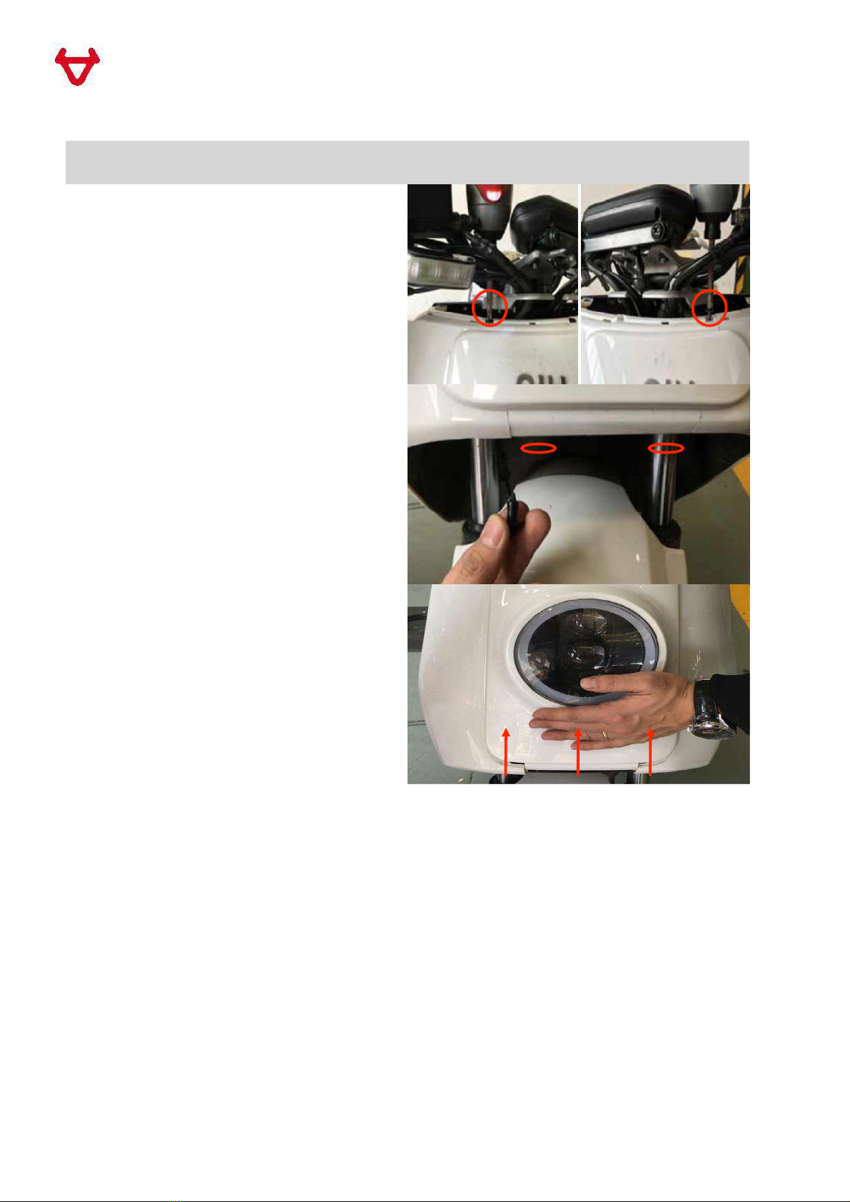
Section 1. Windshield
1.1 Unscrew two screws on the Windshield
(earlier models may have 3 screws)
Section 2. Front Neck Cover
2.1 Remove two Front Central Cover
Rubber Plugs and unscrew two screws
inside
2.2 Remove Front Neck Cover by lifting it
at front
V1.0.0
13
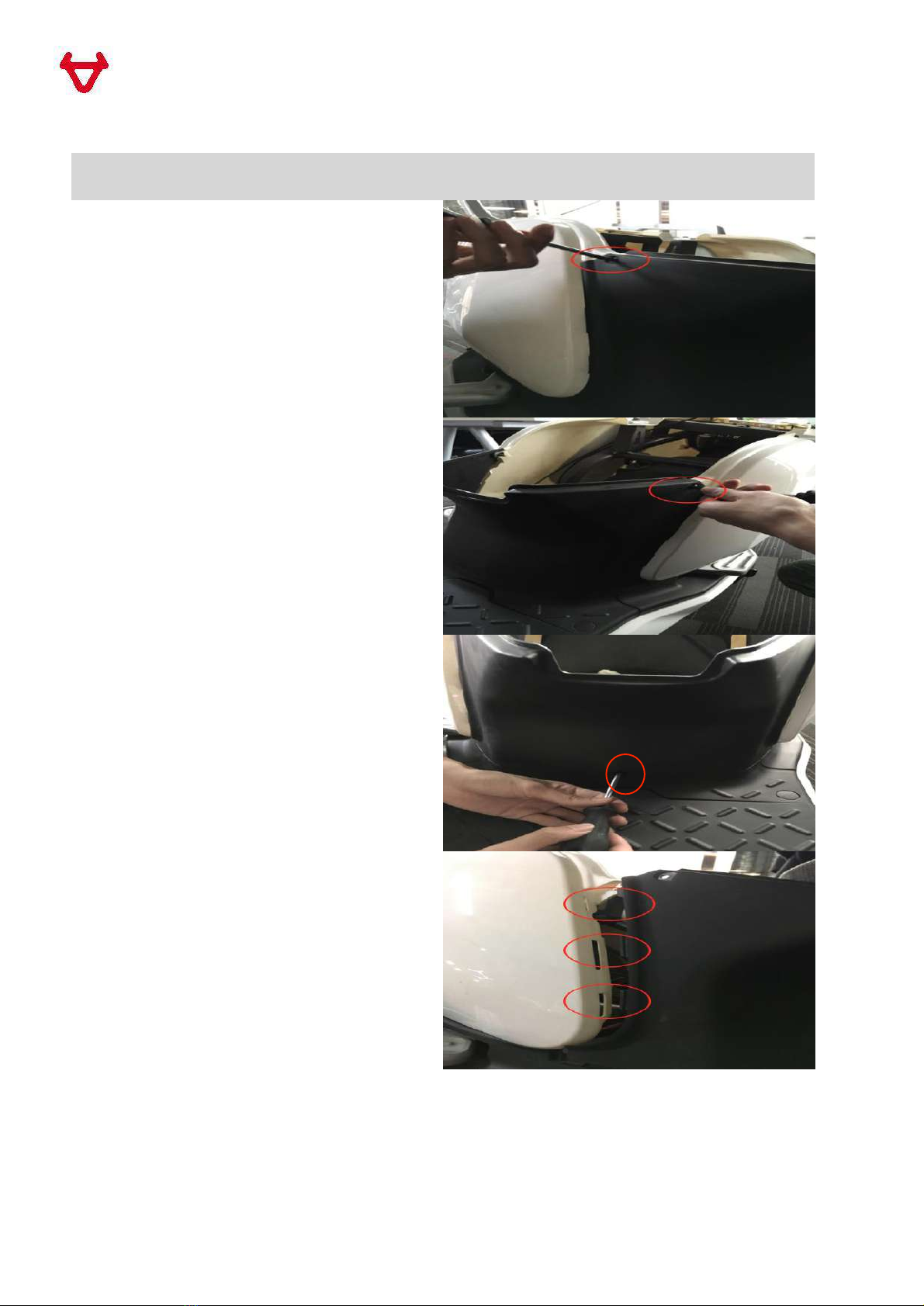
Section 3. Front Panel
3.1 Unscrew two screws on the top of Front
Panel
3.2 Take out two Push-in Rivets from the
bottom of Front Panel
3.3 Remove Front Panel by pushing it
upward

V1.0.0
14
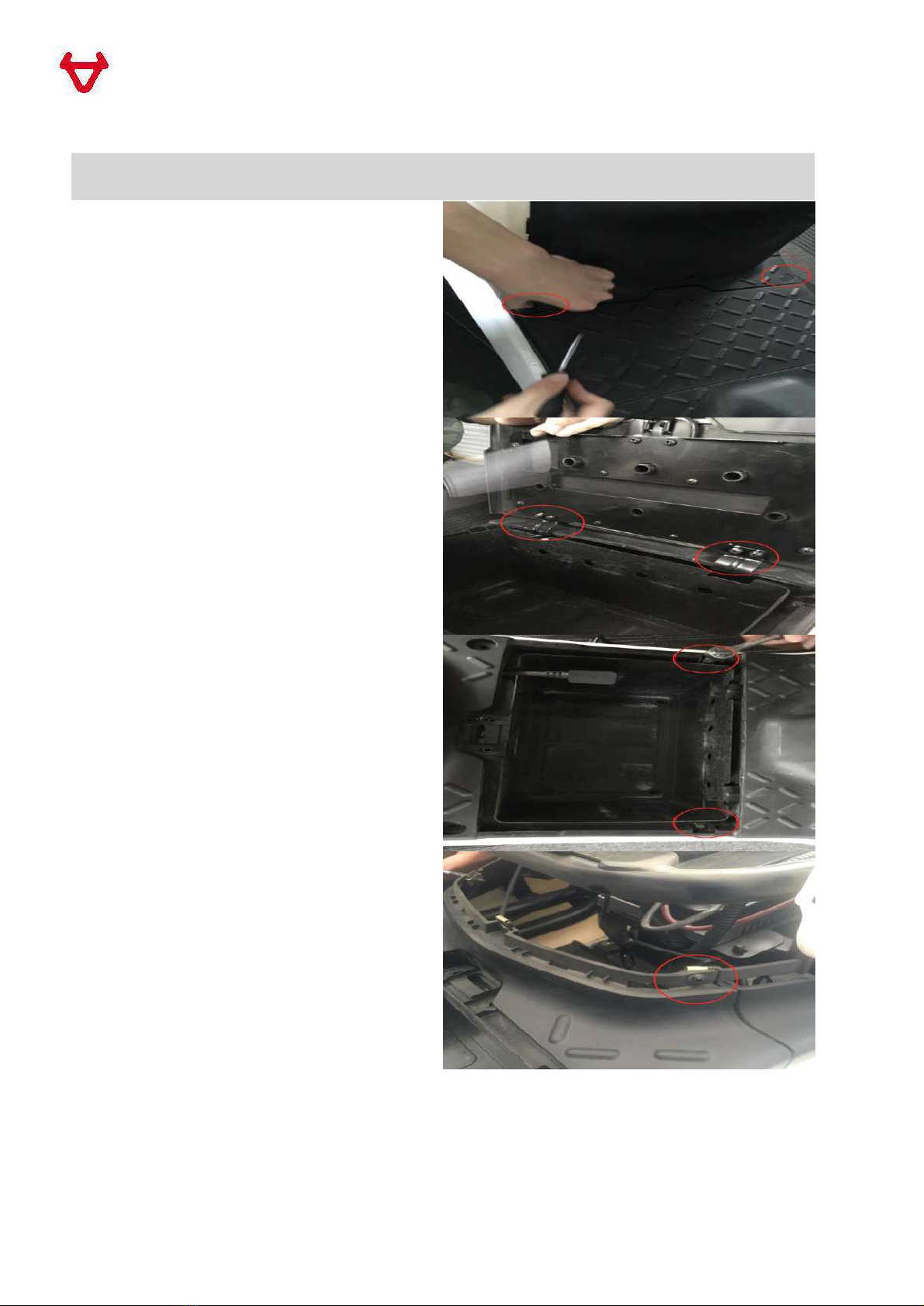
Section 4. Under Seat Storage Compartment
4.1 Unscrew four screws in the Under Seat
Storage Compartment
4.2 Lift up the Under Seat Storage
Compartment, disconnect the two
connectors
4.3 Pull Battery Compartment Lock cable
out
V1.0.0
15
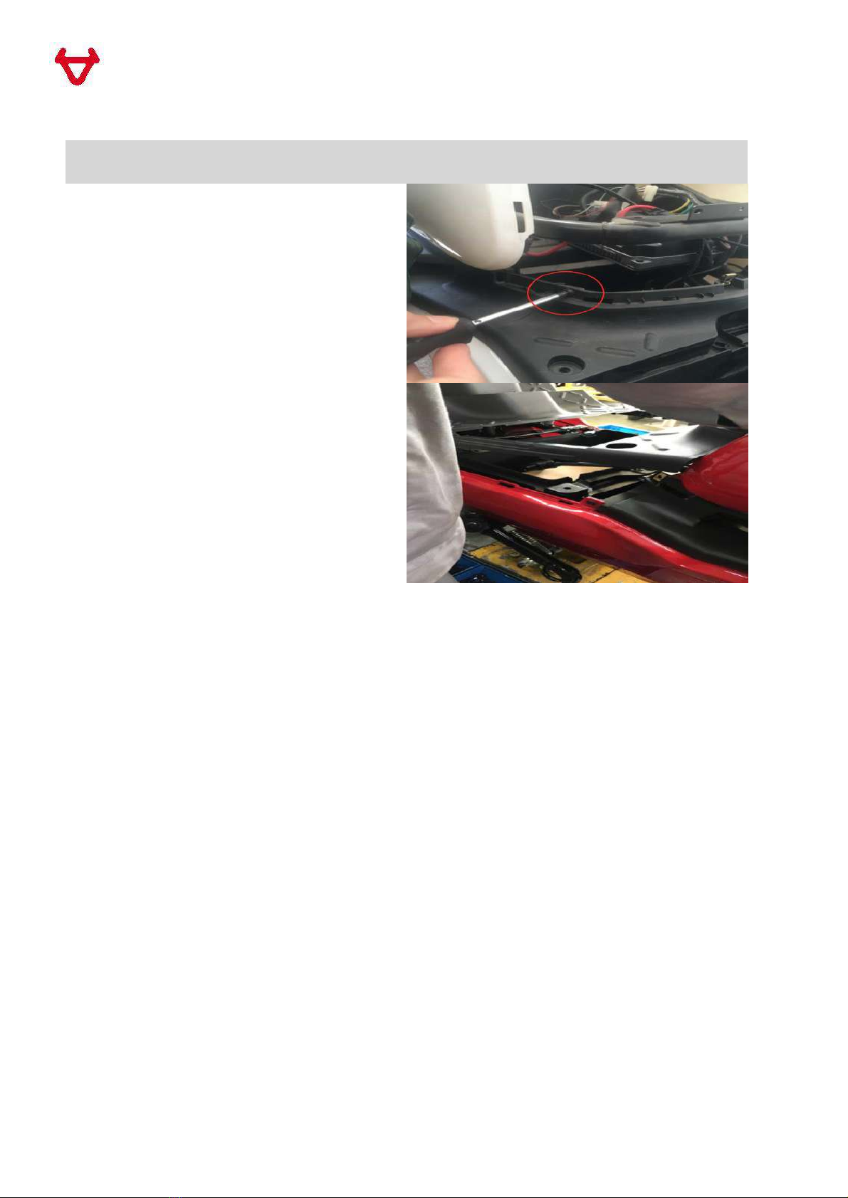
Section 5. Rear Central Cover
5.1 Unscrew the left side screw
5.2 Unscrew the right side screw
5.3 Pull out the rubber cover and unscrew
the screw
5.4 Pull out Rear Central Cover carefully
V1.0.0
16
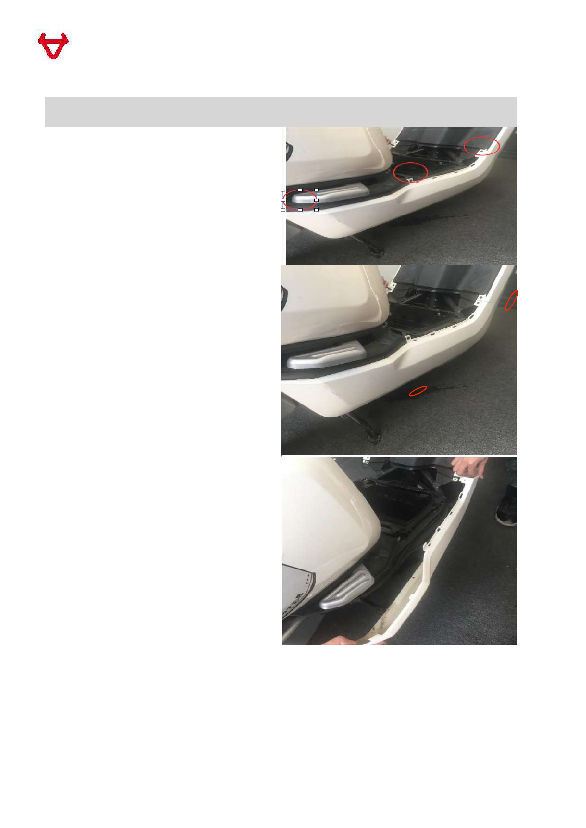
Section 6. Battery Compartment Cover and Footrest
6.1 Pull out the footrest plug and unscrew
two hexagon flange bolt
6.2 Unscrew four cross recessed pan head
tapping screws and remove Battery
Compartment Cover
6.3 Unscrew two hexagon flange bolts
6.4 Unscrew right side screw
V1.0.0
17
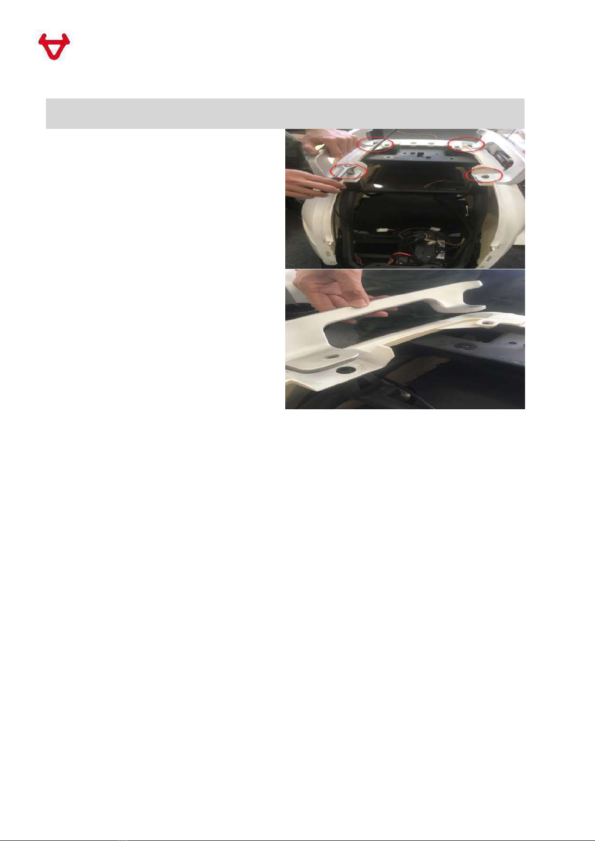
Section 6. Battery Compartment Cover and Footrest
6.5 Unscrew left side screw
6.6 Pull out the Footrest
V1.0.0
18
Section 7. Side Panel
7.1 Unscrew left side screw
7.2 Unscrew two screws in dark side
7.3 Pull out the whole side panel
V1.0.0
19
Section 8. Handrail
8.1 Remove four Hexagon flange bolts
marked in the guide photo
8.2 Pull out the Handrail

V1.0.0
20
Section 9. End cap and Body Cover
9.1 Unscrew four cross recessed medium
pan head bolts
9.2 Unscrew Cross recessed pan head
tapping screw
9.3 Unscrew two cross recessed pan head
tapping screws
9.4 Pull out the whole body panel
Table of contents
Other niu Scooter manuals


