Vega VEGADIF 65 User manual

Operating Instructions
VEGADIF 65
4…20 mA/HART
Document ID:
36128
Differential pressure
p

Contents
1About this document
1.1Function.................................. 5
1.2Target group .............................. 5
1.3Symbolism used............................ 5
2For your safety
2.1Authorised personnel ........................ 6
2.2Appropriate use ............................ 6
2.3Warning about misuse ....................... 6
2.4General safety instructions . . . . . . . . . . . . . . . . . . . . 6
2.5Safety label on the instrument . . . . . . . . . . . . . . . . . . 7
2.6CE conformity ............................. 7
2.7Fulfillment of NAMUR recommendations . . . . . . . . . . 7
2.8Safety instructions for Ex areas . . . . . . . . . . . . . . . . . 7
2.9Safety instructions for oxygen applications . . . . . . . . . 7
2.10 Environmental instructions..................... 7
3Product description
3.1Configuration .............................. 9
3.2Principle of operation ........................ 10
3.3Operation................................. 14
3.4Packaging,transport and storage ............... 14
4Mounting
4.1General instructions ......................... 16
4.2Special application conditions . . . . . . . . . . . . . . . . . . 17
4.3Flow measurement .......................... 18
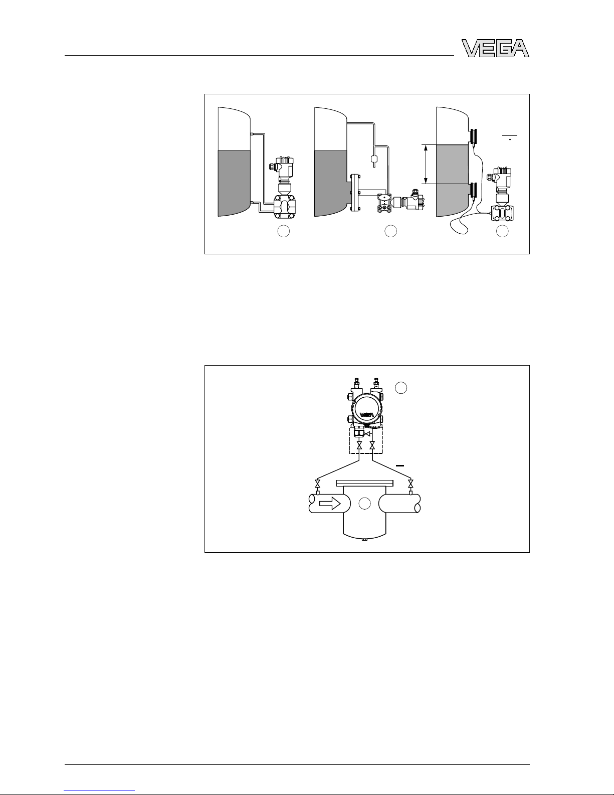
4.4Level measurement ......................... 20
4.5Density and interface measurement. . . . . . . . . . . . . . 25
4.6Differential pressure measurement............... 27
4.7Wall or tube mounting........................ 29
4.8External housing............................ 29
4.9Mounting control............................ 30
5Connect to power supply
5.1Prepare the connection....................... 31
5.2Connection procedure........................ 32
5.3Single chamber housing . . . . . . . . . . . . . . . . . . . . . . 35
5.4Double chamber housing ..................... 36
5.5Double chamber housing Ex d . . . . . . . . . . . . . . . . . 37
5.6Version IP 66/IP 68,1bar..................... 38
5.7External housing with version IP 68 . . . . . . . . . . . . . . 38
5.8Switch on phase............................ 39
6Adjustment with the indicating and adjustment module
PLICSCOM
6.1Short description ........................... 41
6.2Insert indicating and adjustment module. . . . . . . . . . . 41
6.3Adjustment system .......................... 43
2VEGADIF 65 •4…20 mA/HART
Contents
36128-EN-090604

6.4Set parameters............................. 44
6.5Menu schematic............................ 53
6.6Saving the parameter adjustment data . . . . . . . . . . . . 57
7Operating with PACTware and other adjustment programs
7.1Connect the PC via VEGACONNECT . . . . . . . . . . . . 58
7.2Parameter adjustment with PACTware . . . . . . . . . . . . 59
7.3Parameter adjustment with AMS™and PDM . . . . . . . 60
7.4Saving the parameter adjustment data . . . . . . . . . . . . 60
8Set up
8.1Select the mode............................ 61
8.2Flow measurement .......................... 61
8.3Level measurement ......................... 63
8.4Density and interface measurement. . . . . . . . . . . . . . 67
8.5Differential pressure measurement............... 67
9Maintenance and fault rectification
9.1Maintain.................................. 70
9.2Remove interferences........................ 70
9.3Exchanging the electronics module . . . . . . . . . . . . . . 71
9.4Software update ............................ 71
9.5Instrument repair ........................... 72
10 Dismounting
10.1Dismounting steps .......................... 73
10.2Disposal ................................. 73
11 Supplement
11.1Technical data ............................. 74
11.2Dimensions ............................... 86
Supplementary documentation
Information:
Supplementary documents appropriate to the ordered version come
with the delivery.You can find them listed in chapter "Product
description".
Instructions manuals for accessories and replacement parts
Tip:
To ensure reliable setup and operation of your instrument,we offer
accessories and replacement parts.The corresponding instructions
manuals are:
l27720 -External indication VEGADIS 61
l34296 -Protective cover
l36132 -Electronics module DF60 for VEGADIF 65
VEGADIF 65 •4…20 mA/HART 3
Contents
36128-EN-090604

1About this document
1.1Function
This operating instructions manual provides all the information you
need for mounting,connection and setup as well as important
instructions for maintenance and fault rectification.Please read this
information before putting the instrument into operation and keep this
manual accessible in the immediate vicinity of the device.
1.2Target group
This operating instructions manual is directed to trained qualified
personnel.The contents of this manual should be made available to
these personnel and put into practice by them.
1.3Symbolism used
Information,tip,note
This symbol indicates helpful additional information.
Caution:If this warning is ignored,faults or malfunctions can
result.
Warning:If this warning is ignored,injury to persons and/or serious
damage to the instrument can result.
Danger:If this warning is ignored,serious injury to persons and/or
destruction of the instrument can result.
Ex applications
This symbol indicates special instructions for Ex applications.
lList
The dot set in front indicates a list with no implied sequence.
àAction
This arrow indicates a single action.
1Sequence
Numbers set in front indicate successive steps in a procedure.
4VEGADIF 65 •4…20 mA/HART
1About this document
36128-EN-090604

2For your safety
2.1Authorised personnel
All operations described in this operating instructions manual must be
carried out only by trained specialist personnel authorised by the plant
operator.
During work on and with the device the required personal protective
equipment must always be worn.
2.2Appropriate use
VEGADIF 65 is a differential pressure transmitter for measurement of
flow,level,differential pressure,density and interface.
You can find detailed information on the application range in chapter
"Product description".
Operational reliability is ensured only if the instrument is properly used
according to the specifications in the operating instructions manual as
well as possible supplementary instructions.
For safety and warranty reasons,any invasive work on the device
beyond that described in the operating instructions manual may be
carried out only by personnel authorised by the manufacturer.Arbitrary
conversions or modifications are explicitly forbidden.
2.3Warning about misuse
Inappropriate or incorrect use of the instrument can give rise to
application-specific hazards,e.g.vessel overfill or damage to system
components through incorrect mounting or adjustment.
2.4General safety instructions
This is a high-tech instrument requiring the strict observance of
standard regulations and guidelines.The user must take note of the
safety instructions in this operating instructions manual,the country-
specific installation standards as well as all prevailing safety
regulations and accident prevention rules.
The instrument must only be operated in a technically flawless and
reliable condition.The operator is responsible for trouble-free
operation of the instrument.
During the entire duration of use,the user is obliged to determine the
compliance of the required occupational safety measures with the
current valid rules and regulations and also take note of new
regulations.
VEGADIF 65 •4…20 mA/HART 5
2For your safety
36128-EN-090604

2.5Safety label on the instrument
The safety approval markings and safety tips on the device must be
observed.
2.6CE conformity
This device fulfills the legal requirements of the applicable EC
guidelines.By attaching the CE mark,VEGA provides a confirmation
of successful testing.You can find the CE conformity declaration in the
download area of www.vega.com.
2.7Fulfillment of NAMUR recommendations
With respect to compatibility,the NAMUR recommendation NE 53 is
fulfilled.This applies also to the corresponding indicating and
adjustment components.VEGA instruments are generally upward and
downward compatible.
lSensor software to DTM VEGADIF 65
lDTM VEGADIF 65 for adjustment software PACTware
lIndicating and adjustment module for sensor software
The parameter adjustment of the basic sensor functions is independ-
ent of the software version.The range of available functions depends
on the respective software version of the individual components.
2.8Safety instructions for Ex areas
Please note the Ex-specific safety information for installation and
operation in Ex areas.These safety instructions are part of the
operating instructions manual and come with the Ex-approved
instruments.
2.9Safety instructions for oxygen applications
For instruments in oxygen applications the special instructions in
chapters "Storage and transport","Mounting"as well as "Technical
data"under "Process conditions"must be noted.Furthermore the valid
national regulations,implementation instructions and memorandums
of the BG (professional assoc.) must be noted.
2.10 Environmental instructions
Protection of the environment is one of our most important duties.That
is why we have introduced an environment management system with
the goal of continuously improving company environmental protection.
The environment management system is certified according to DIN
EN ISO 14001.
Please help us fulfil this obligation by observing the environmental
instructions in this manual:
6VEGADIF 65 •4…20 mA/HART
2For your safety
36128-EN-090604

lChapter "Packaging,transport and storage"
lChapter "Disposal"
VEGADIF 65 •4…20 mA/HART 7
2For your safety
36128-EN-090604

3Product description
3.1Configuration
The scope of delivery encompasses:
lVEGADIF 65 differential pressure transmitter
lDepending on the version ventilation valves and/or closing screws
lOptional accessory
lDocumentation
-this operating instructions manual
-Operating instructions manual 27835 "Indicating and adjust-
ment module PLICSCOM"(optional)
-Supplementary instructions manual 31708 "Heating for in-
dicating and adjustment module"(optional)
-Operating instructions 36133 "Isolating diaphragm CSB"
(optional)
-Operating instructions 36134 "Isolating diaphragm CSS"
(optional)
-Supplementary instructions manual "Plug connector for con-
tinuously measuring sensors"(optional)
-Ex-specific"Safety instructions"(with Ex-versions)
-Certificate "Oil and grease-free for oxygen applications"(with
respective versions)
-if necessary,further certificates
The following illustration shows the components of VEGADIF 65:
+ –
1
2
3
Fig.1:VEGADIF 65 in basic version
1Housing cover,optionally with integrated indicating and adjustment module
2Housing with electronics
3Process components with measuring cell
The components are available in different versions.
Scope of delivery
Components
8VEGADIF 65 •4…20 mA/HART
3Product description
36128-EN-090604

The type label contains the most important data for identification and
use of the instrument:
lSensor type
lArticle number instrument
lEx approval
lTechnical data:Measuring range,process pressure,process
temperature,signal output,voltage supply,protection,protection
class
lOrder number,serial number instrument
lHardware and software version
lArticle numbers,documentation
The serial number allows you to access the delivery data of the
instrument via www.vega.com,"VEGA Tools"and "serial number
search".In addition to the type label outside,you can also find the
serial number on the inside of the instrument.
3.2Principle of operation
VEGADIF 65 is a differential pressure transmitter for measurement of
flow,level,differential pressure,density and interface.Measured
products are gases,vapours and liquids.
Flow measurement
QQ
p1p1
p2p2
Q ~ p Q ~ p
++ ––
1 2
Fig.2:Flow measurement with VEGADIF 65 and effective pressure transmitter,
Q=flow, Δp=differential pressure, Δp=p
1
-p
2
1Orifice
2Dynamic pressure probe
Type label
Application area
VEGADIF 65 •4…20 mA/HART 9
3Product description
36128-EN-090604

Level measurement
123
h = p
ρ g
+
+
––
h
+ –
Fig.3:Level measurement with VEGADIF 65. Δp=differential pressure,ρ=
density of the medium,g=acceleration of gravity
1Basic version with effective pressure lines
2Version with flange isolating diaphragm
3Version with capillaries and cell isolating diaphragms
Differential pressure measurement
+
2
1
Fig.4:Differential pressure measurement with VEGADIF 65
1Filter
2VEGADIF 65
10 VEGADIF 65 •4…20 mA/HART
3Product description
36128-EN-090604

Density measurement
1
p = p
Mg
+
–
h
Fig.5:Density measurement with VEGADIF 65,h=defined mounting distance,
Δp=differential pressure,ρ=density of the medium,g=acceleration of gravity
1VEGADIF 65
Interface measurement
1
+
–
h
2
3
Fig.6:Interface measurement with VEGADIF 65
1VEGADIF 65
2Liquid with highest density
3Liquid with lowest density
Ametallic measuring cell is used as sensor element.The process
pressures are transmitted via separating diaphragms and filling oils to
the resistance measuring bridge (semi-conductor technology). The
differential-pressure dependent change of the bridge voltage is
measured,further processed and converted into a corresponding
output signal.
Functional principle
VEGADIF 65 •4…20 mA/HART 11
3Product description
36128-EN-090604

The configuration of the measuring cells differs depending on the
measuring range:
1
2
3
4
5
1
p2
p
Fig.7:Metallic measuring cell 10 mbar and 30 mbar -p
1
and p
2
process
pressures
1Measuring element
2Silicone diaphragm
3Separating diaphragm
4Filling oil
5Integrated overvoltage arrester
12
3
4
1
p2
p
Fig.8:Metallic measuring cell from 100 mbar -p
1
and p
2
process pressures
1Measuring element
2Overload diaphragm/Middle diaphragm
3Filling oil
4Separating diaphragm
Two-wire electronics 4…20 mA/HART for power supply and
measured value transmission over the same cable.
The supply voltage range can differ depending on the instrument
version.
The data for power supply are specified in chapter "Technical data".
The optional background lighting of the indicating and adjustment
module is powered by the sensor.Acertain level of operating voltage
is required for this.You can find the exact voltage specifications in
chapter "Technical data".
Power supply
12 VEGADIF 65 •4…20 mA/HART
3Product description
36128-EN-090604

The optional heating requires its own operating voltage.You can find
details in the supplementary instructions manual "Heating for indicat-
ing and adjustment module".
This function is generally not available for approved instruments.
3.3Operation
VEGADIF 65 can be adjusted with different adjustment media:
lwith indicating and adjustment module
lwith the suitable VEGA DTM in conjunction with an adjustment
software according to the FDT/DTM standard,e.g.PACTware and
PC
lwith manufacturer-specific adjustment programs AMS™or PDM
lWith a HART handheld
3.4Packaging,transport and storage
Your instrument was protected by packaging during transport.Its
capacity to handle normal loads during transport is assured by a test
according to DIN EN 24180.
The packaging of standard instruments consists of environment-
friendly,recyclable cardboard.For special versions,PE foam or PE foil
is also used.Dispose of the packaging material via specialised
recycling companies.
Caution:
Instruments for oxygen applications are sealed in PE foil and provided
with a label "Oxygen!Use no Oil".Remove this foil just before
mounting the instrument!See instruction under "Mounting".
Transport must be carried out under consideration of the notes on the
transport packaging.Nonobservance of these instructions can cause
damage to the device.
The delivery must be checked for completeness and possible transit
damage immediately at receipt.Ascertained transit damage or
concealed defects must be appropriately dealt with.
Up to the time of installation,the packages must be left closed and
stored according to the orientation and storage markings on the
outside.
Unless otherwise indicated,the packages must be stored only under
the following conditions:
lNot in the open
lDry and dust free
lNot exposed to corrosive media
lProtected against solar radiation
Packaging
Transport
Transport inspection
Storage
VEGADIF 65 •4…20 mA/HART 13
3Product description
36128-EN-090604

lAvoiding mechanical shock and vibration
lStorage and transport temperature see chapter "Supplement -
Technical data -Ambient conditions"
lRelative humidity 20 …85 %
Storage and transport
temperature
14 VEGADIF 65 •4…20 mA/HART
3Product description
36128-EN-090604

4Mounting
4.1General instructions
Make sure that all parts of the instrument exposed to the process,in
particular the sensor element,process seal and process fitting,are
suitable for the existing process conditions.These include above all
the process pressure,process temperature as well as the chemical
properties of the medium.
You can find the specifications in chapter "Technical data"or on the
type label.
Use the recommended cables (see chapter "Connecting to power
supply")and tighten the cable gland.
You can give your VEGADIF 65 additional protection against moisture
penetration by leading the connection cable downward in front of the
cable entry.Rain and condensation water can thus drain off.This
applies mainly to outdoor mounting as well as installation in areas
where high humidity is expected (e.g.through cleaning processes)or
on cooled or heated vessels.
The ventilation for the electronics housing is realised via a filter
element in the vicinity of the cable glands.
2
1
2
1
2
1
1
2
Fig.9:Position of the filter element.Upper row single chamber housing,lower
row double chamber housing
1Filter element for ventilation of the electronics housing
2Blind stopper
Information:
Make sure that the filter element is always free of buildup during
operation.Ahigh-pressure cleaner must not be used for cleaning.
Suitability for process
conditions
Moisture
Ventilation
VEGADIF 65 •4…20 mA/HART 15
4Mounting
36128-EN-090604

You find general recommendations for wiring of effective pressure
lines in DIN 19210 "Effective pressure lines for flow systems"or the
corresponding national or international standards.When wiring
effective pressure lines outdoors,keep in mind to use a suitable
antifreeze,e.g.by using tube heat tracing.Wire effective pressure
lines with a monotonic decrease of at least 10 %.
In case of strong vibrations at the application position,the instrument
version with external electronics should be used.
Higher process temperatures often mean also higher ambient
temperatures for electronics and connection cable.Make sure that the
upper temperature limits stated in chapter "Technical data"for the
environment of the electronics housing and connection cable are not
exceeded.
4.2Special application conditions
Oxygen and other gases can be explosive with oils,grease and
plastics so that the following provisions must also be taken:
lAll components of the plant,such as e.g.measuring instruments
must be cleaning according to the requirements of BAM
(DIN 19247)
lDepending on the materials used,a certain max.temperature and
pressure must not be exceeded in oxygen applications
Danger:
Instruments for oxygen applications must be unpacked just before
mounting.After removing the protective cover of the process fitting,the
label "O₂"will be visible on the process fitting.Penetration of oil,
grease and dirt should be avoided.Danger of explosion!
In addition,VEGA offers oil and grease-free instruments for special
applications such as e.g.pure gas.There are no special restrictions in
respect to the process conditions.
Effective pressure lines
Vibrations
Temperature limits
Oxygen applications
Pure gas applications
16 VEGADIF 65 •4…20 mA/HART
4Mounting
36128-EN-090604

4.3Flow measurement
àMount VEGADIF 65 above the measurement loop so that
condensate can drain offin the process cable.
+–
1
2
4
3
Fig.10:Measurement setup,flow measurement in gases
1VEGADIF 65
2Three-fold valve block
3Block valves
4Orifice or impact pressure probe
àMount VEGADIF 65 below the measurement loop
àMount condensate vessels at the same height with the discharge
socket and at the same distance to VEGADIF 65
àFor measurements in products with solid content such as e.g.dirty
liquids,the installation of separators and drain valves is
recommended to enable collection and removal of debris and
sediment.
àFill the effective pressure lines to the height of the condensate
vessels before setup
In gases
In vapours
VEGADIF 65 •4…20 mA/HART 17
4Mounting
36128-EN-090604

+ –
1
2 33
55
66
7
4
Fig.11:Measurement setup,flow measurement in vapours
1Condensate vessels
2Orifice or impact pressure probe
3Block valves
4VEGADIF 65
5Precipitator
6Drain valves
7Three-fold valve block
àMount VEGADIF 65 below the measurement loop so that the
effective pressure lines are always filled with liquid and gas
bubbles can bubble up to the process line
àFor measurements in products with solid content such as e.g.dirty
liquids,the installation of separators and drain valves is
recommended to enable collection and removal of debris and
sediment.
àFill the effective pressure lines to the height of the condensate
vessels before setup
In liquids
18 VEGADIF 65 •4…20 mA/HART
4Mounting
36128-EN-090604

+ –
1
2 2
3
5 5
6
4 4
Fig.12:Measurement setup,flow measurement in liquids
1Orifice or impact pressure probe
2Block valves
3VEGADIF 65
4Precipitator
5Drain valves
6Three-fold valve block
4.4Level measurement
àMount VEGADIF 65 below the lower measurement connection so
that the effective pressure lines are always filled with liquid
àMinus side is open to the atmospheric pressure
In open vessels with
effective pressure line
VEGADIF 65 •4…20 mA/HART 19
4Mounting
36128-EN-090604

àFor measurements in products with solid content such as e.g.dirty
liquids,the installation of separators and drain valves is
recommended to enable collection and removal of debris and
sediment.
+
p
atm
min. patm
2
3
4
5
1
Fig.13:Measurement setup,level measurement in the open vessel
1VEGADIF 65
2Minus side is open to the atmospheric pressure
3Block valve
4Precipitator
5Drain valve
àMount VEGADIF 65 directly to the vessel
àMinus side is open to the atmospheric pressure
+
min.
p
atm
patm
1
2
+ –
Fig.14:Measurement setup,level measurement in the open vessel
1VEGADIF 65
2Minus side is open to the atmospheric pressure
àMount VEGADIF 65 below the lower measurement connection so
that the effective pressure lines are always filled with liquid
àConnect minus side always above the max.level
In open vessels with
unilateral pressure
transmitter
In closed vessels with
effective pressure lines
20 VEGADIF 65 •4…20 mA/HART
4Mounting
36128-EN-090604
Other manuals for VEGADIF 65
6
Table of contents
Other Vega Transmitter manuals

Vega
Vega VEGABAR 54 User manual

Vega
Vega VEGABAR 81 User manual

Vega
Vega VEGABAR 82 User manual

Vega
Vega VEGABAR 87 User manual

Vega
Vega VEGABAR 81 User manual

Vega
Vega VEGABAR 87 User manual

Vega
Vega VEGABAR 82 User manual

Vega
Vega VEGAWELL 52 User manual

Vega
Vega VEGABAR 81 User manual

Vega
Vega VEGABAR 82 User manual

Vega
Vega VEGABAR 81 User manual

Vega
Vega VEGABAR 66 User manual

Vega
Vega VEGABAR 87 User manual

Vega
Vega VEGABAR 86 User manual

Vega
Vega VEGABAR 83 User manual

Vega
Vega VEGADIF 85 User manual

Vega
Vega VEGAFLEX 80 series User guide

Vega
Vega VEGABAR 53 User manual

Vega
Vega VEGADIF 85 User manual

Vega
Vega VEGABAR 86 User manual