NoiseKen GT-30RA User manual

INSTRUCTION MANUAL
DISCHARGE GUN for ELECTROSTATIC TESTING
MODEL GT-30RA
GT-30R3302KA
NOISE LABORATORY CO., LTD.
2017.10 Edition 1.02
AEC00315-00E-0C
•
Thank you very much for your purchasing this instrument.
• This instrument generates high voltage.
Since failure to follow instructions for handling this instrument may
cause an electric shock or other kinds of accidents, please be careful for
safety in handling this instrument.
•
Please read this booklet carefully, understand its content well to use this
instrument safely and properly, and keep it by your side or other proper
location so that it may be always readily available.

NOTICE
• No part of this booklet may be reproduced or transferred, in any form, for any purpose, without the
permission of Noise Laboratory Co., Ltd.
• The contents of this booklet have been thoroughly checked. However, if a doubtful point, an error in
writing or a missing is found, please contact us.
• Noise Laboratory Co., Ltd. shall have no liability for any trouble resulting from the misuse or improper
handling of this product regardless of the contents of this booklet or arising from the repair or
remodeling of this product by a third party other than Noise Laboratory Co., Ltd. or its authorized
person.
• Noise Laboratory Co., Ltd. shall have no liability for any trouble resulting from the remodeling or
modification of this product.
• n no event shall Noise Laboratory Co., Ltd. be liable for any results arising from the use of this
product.
• Trademarks, company names, and similar that appear in this document are trademarks or registered
trademarks of their respective companies. This document does not use the TM and symbols.
1
The instrument may only be used by trained EMC technicians
(electrical technicians)
There is a risk of death or serious injury, and of the emission of electromagnetic
noise that exceeds the stipulated limits. Please use the instrument in
conjunction with appropriate measures for dealing with electromagnetic noise
such as a Faraday cage or shielded room
.
Do not use the instrument for any purposes other than the EMC
testing purposes described in this instruction manual
Failure to follow this rule risks death or serious injury.
The instrument may not be used by people fitted with electronic
medical devices such as pacemakers and such people may not
enter the testing site while the instrument is operating
Failure to follow this rule risks death or serious injury.
The instrument may not be used in a location where fire is
prohibited or there is a risk of explosion
Failure to follow this rule risks igniting a fire due to an electrical discharge.
1. IMPORTANT SAFETY PRECAUTIONS
The "Important Safety Precautions" explain rules that must e followed to prevent any risk of
harm or injury to the user of the instrument or to other people.
Before setting up the test site, connecting the equipment, or starting testing,
please read the Chapter entitled "Basic Safety Precautions for the Safe Use of
the Simulator" which contains additional safety advice.

2
2. CHECK PACKAGE CONTENTS
Before using the instrument, please check that none of the main unit and
associated items is missing.
This product can be used to perform the tests that conform to different test standards by
changing the CR unit and discharge cup.
For that reason, the product is available in two different sets. This section shows what is
supplied with each set. Read it according to the contents of your set.
2–1. GT-30RA (Set for Test under EC 61000-4-2)
2–2. GT-30R3302KA (Set for 330Ω&2kΩ Test under SO 10605)
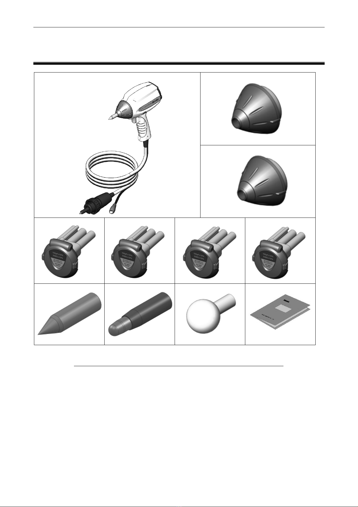
2–1. GT-30RA (Set for Test under IEC 61000-4-2)
A
B
C
D
E
F
tem Quantity
A: Main unit of the discharge gun ·············································· 1
B: 330Ω testing discharge cup (Attached to the main unit) ·············· 1
C: CR unit 150pF-330Ω (Attached to the main unit) ······················ 1
D: Contact discharge tip (Conical) ············································ 1
E: Air discharge tip (Round) ····················································· 1
F: nstruction manual (This book) ·············································· 1
2. CHECK PACKAGE CONTENTS
3
2–2. GT-30R3302KA (Set for 330Ω&2kΩ Test under ISO 10605)
A
B
C
D
E F G
H
J
K
tem Quantity
A: Main unit of the discharge gun ·············································· 1
B: 330Ω testing discharge cup (Attached to the main unit) ·············· 1
C: 2kΩ testing discharge cup ·················································· 1
D: CR unit 150pF-330Ω (Attached to the main unit) ······················ 1
E: CR unit 150pF-2kΩ ··························································· 1
F: CR unit 330pF-2kΩ ····························································· 1
G: CR unit 330pF-330Ω ·························································· 1
H: Contact discharge tip (Conical) ············································· 1
: Air discharge tip (Round) ······················································ 1
J: High voltage air discharge tip (SphericalΦ30mm) ······················ 1
K: nstruction manual (This book) ·············································· 1

4

5
3. APPLICATION FORM FOR INSTRUCTION MANUAL
To: Noise Laboratory Co., Ltd. via sales agent
We place an order for an instruction manual.
Model Name
Serial No.
Applicant Address
Cut Line
Company Name
Department
Contact Person
Phone No.
FAX No.
Cut off this page "PURCHASE ORDER FOR
INSTRUCTION MANUAL" from this volume and keep it
for future use with care
When an INSTRUCTION MANUAL is required, fill in the a ove Ap
plication
Form and mail or fax it to your nearest sales agent of Noise La oratory or
Noise La oratory.
Cut Line

6

7
4. TABLE OF CONTENTS
1. IMPORTANT SAFETY PRECAUTIONS ....................................................................................... 1
2. CHECK PACKAGE CONTENTS................................................................................................... 2
2–1.
GT-30RA (Set for Test under IEC 1000-4-2) ........................................................................................... 2
2–2.
GT-30R3302KA (Set for 330Ω&2kΩ Test under ISO 10 05) .................................................................... 3
3. APPLICATION FORM FOR INSTRUCTION MANUAL ................................................................ 5
4. TABLE OF CONTENTS ................................................................................................................ 7
5. PREFACE ...................................................................................................................................... 9
5–1.
Features ................................................................................................................................................... 9
5–2.
Combinations with Simulator Base Units .................................................................................................. 9
6. BASIC SAFETY PRECAUTIONS FOR THE SAFE USE OF THE SIMULATOR ...................... 10
–1.
Meaning of Safety Symbols .................................................................................................................... 10
–2.
DANGER Alerts ....................................................................................................................................... 11
–3.
WARNING Alerts ..................................................................................................................................... 11
–4.
CAUTION Alerts ..................................................................................................................................... 13
7. POINTS TO NOTE REGARDING CONSUMABLES ITEMS ................................................... 15
7–1.
High Voltage Relay ................................................................................................................................. 15
7–2.
Discharge Tip ......................................................................................................................................... 15
7–3.
CR Unit ................................................................................................................................................... 15
. INTRODUCTION .......................................................................................................................... 16
8–1.
How to Read This Document .................................................................................................................. 1
8–2.
Terms and Definitions ............................................................................................................................. 17
9. NAME AND FUNCTION OF EACH PART .................................................................................. 1
9–1.
External Appearance and Descriptions .................................................................................................. 18
10. SIMULATOR MAIN UNIT AND CONNECTIONS ........................................................................ 22
10–1.
Connection to The Simulator Main Unit .................................................................................................. 23
11. HOW TO REPLACE COMPONENT UNITS................................................................................ 24
11–1.
Discharge Cup........................................................................................................................................ 24
Combination of Discharge Cup and CR Unit ....................................................................................................... 24
Replacing Discharge Cup ................................................................................................................................... 25
11-2. Discharge Tip ................................................................................................................................................. 2
Types of Discharge Tips and Their Applications ................................................................................................. 26
Replacing Discharge Tip ..................................................................................................................................... 2
11-3. CR Unit .......................................................................................................................................................... 28
Replacing CR Unit .............................................................................................................................................. 28
11-4.
GND Clip ................................................................................................................................................ 29
12. OPERATION ................................................................................................................................ 30
12–1.
Starting Test ............................................................................................................................................ 30
12–2.
LED Light ............................................................................................................................................... 31
12–3.
Stopping a Test ....................................................................................................................................... 31
13. SPECIFICATIONS ....................................................................................................................... 32
13–1.
List of Specifications ............................................................................................................................... 32
13–2.
Discharge Parameters and Waveform (150pF-330Ω, 330pF-330Ω) ...................................................... 33
13–3.
Discharge Parameters and Waveform (150pF-2000Ω, 330pF-2000Ω) .................................................. 34

4. TABLE OF CONTENTS
8
14. CHECKING WAVEFORM ............................................................................................................ 35
14–1.
Equipment and Configuration ................................................................................................................. 35
14–2.
Accessories for Observing Waveform .................................................................................................... 35
15. ABOUT AIR DISCHARGE ........................................................................................................... 36
15–1.
ESD Testing to the IEC standard ............................................................................................................ 3
15–2.
IEC standard requirement for an ESD generator for the air discharge method ...................................... 3
15–3.
ESD test circuit operations in the air discharge mode ............................................................................ 3
15–4.
Charge leakage in the air discharge mode ............................................................................................. 37
15–5.
Air discharge testing and humidity .......................................................................................................... 37
15– .
Temperature/humidity requirement ......................................................................................................... 38
16. CLEANING PROCEDURES ........................................................................................................ 39
1 –1.
CLEANING IS CRITICAL ....................................................................................................................... 39
1 –2.
Area to be cleaned ................................................................................................................................. 39
1 –3.
Cleaning method .................................................................................................................................... 40
1 –4.
Cleaning interval ..................................................................................................................................... 40
17. RELATED ACCESSORIES ......................................................................................................... 41
1 . CALIBRATION ............................................................................................................................. 42
19. WARRANTY ................................................................................................................................ 43
20. MAINTENANCE ........................................................................................................................... 45
21. CONTACTING TECHNICAL SUPPORT ..................................................................................... 46
22. INFORMATION FOR CE MARKING, EU AND EUROPEAN TERRITORIES ............................ 47
9
5. PREFACE
Thank you very much for your purchase of the discharge gun for electrostatic discharge testing
“GT-30RA”. t is recommended that the contents of this manual should be thoroughly understood
and used as a ready reference for operation.
To ensure the safety and procedure of electrostatic tests, thoroughly read this nstruction Manual
together with the instruction manual for Electrostatic Discharge Simulator to be connected to this
product.
This Instruction Manual was prepared so that any person who can observe the
prescribed instruction method and operating precautions may safely handle and
fully utilize this discharge gun.
This product shall be used with Noise en ESD simulator base unit. Some
functions do not work when used with older base units. For details, refer to 5-2
“Combinations with Simulator Base Units”
eep this Instruction Manual by your side or other proper location so that it may
be readily available when using this discharge gun.
5–1. Features
This product is an electrostatic discharge gun conforming to IEC 61000-4-2 and is designed
to generate static electricity for conducting the electrostatic discharge immunity test. When
conducting the electrostatic test, this product should e connected to the Noiseken’s
Electrostatic Discharge Simulator (e.g. ESS-S3011A, ESS-B3011A).
Changing the discharge cup and CR unit makes it possi le to perform the electrostatic
discharge immunity test conforming to ISO 10605.
As for conforming standard and com ination of the units, refer to Ta le 11.1, Ta le 11.2,
Chapter 13.SPECIFICATIONS and Chapter 17.RELATED ACCESSORIES.
5–2. Com inations with Simulator Base Units
This product is a discharge gun used to perform electrostatic tests. ts available functions vary,
depending on the simulator used in the combination with it.
Simulator model Connectivity
/Availability Functional restriction on this instrument
ESS-S3011A/ ESS-S3011 No functional restrictions
ESS-B3011A/ ESS-B3011
ESS-2000AX
The following functions are not available.
Discharge detection
Pre-check
LED light illuminating EUT
CR & cup combination recognition
ESS-2002EX
ESS-2000
ESS-2002
: Recommended combination, which can be connected and used without any functional restriction.
: Can be connected and used but some functions are not available.

10
6. BASIC SAFETY PRECAUTIONS FOR THE SAFE
USE OF THE SIMULATOR
The "Basic Safety Precautions" explain rules that must e followed to prevent damage
to property or injury to the user of the instrument or to other people.
The sym ols elow are used to indicate the level of injury or damage that may result if
the instrument is used in a way that ignores these precautions. Please take careful note
of the meanings of these sym ols efore proceeding to read this manual.
6–1. Meaning of Safety Sym ols
The following sym ols indicate the level of injury or damage that may result if the
instrument is used incorrectly in a way that ignores the associated precautions.
This sym ol indicates that failure to comply with the associated precaution "is
highly likely to result in the risk of death or serious injury".
This sym ol indicates that failure to comply with the associated precaution "may
result in death or serious injury".
This sym ol indicates that failure to comply with the associated precaution "may
result in damage ut that only physical damage is likely to occur".
The following sym ols indicate the nature of the associated precaution.
Indicates a warning
(a situation where caution is
required).
Indicates a prohi ition (an
action that is not allowed to
occur).
Indicates an instruction (an
action that must always e
taken).
Prohibited
Safety Rule
Always earth correctly
Unplug from
Mains Power
Disassembly
Prohibited

. BASIC SAFETY PRECAUTIONS FOR THE SAFE USE OF THE SIMULATOR
11
6–2. DANGER Alerts
Do not disassemble or modify
Do not remove the cover
Failure to comply with the precaution may result in death or serious injury and possi le
consequences include fire and electric shock
.
For inspection or repair of internal components, please contact your sales agent or the Noise
Laboratory repair and calibration center.
6–3. WARNING Alerts
コンセントから電源プラグを抜くコンセントから電源プラグを抜く
Stop using the instrument immediately if any of the following problems occur
Unit emits smoke and an unusual smell
Water or other foreign material has got inside the unit
Unit is dropped or damaged
AC power cable is damaged (possibly exposing or disconnecting the wires, etc.)
Continuing to use the instrument in a faulty condition risks causing fire, electric shock, or similar.
Disconnect from the power supply immediately and unplug the AC plug from the socket.
After confirming that no more smoke is being emitted, send the instrument to your sales agent or
the Noise Laboratory repair and calibration center for repair. Repairing the instrument yourself is
dangerous and should never be attempted.
Turn the power switch to "Off" on the instrument before connecting or changing
any of the cables
Failure to comply with this rule may result in electric shock or misoperation.
Disassembly
Prohibited
Unplug from Mains Power
Safety Rule
. BASIC SAFETY PRECAUTIONS FOR THE SAFE USE OF THE SIMULATOR
12
強制
Only use the instrument with a power supply voltage and frequency that is within
the indicated range (AC 100V to 240V, 50Hz/60Hz)
Using the instrument with a power supply voltage or frequency outside the indicated range may
result in fire or electric shock.
Firmly insert the AC power cable plug into the socket
Failing to fully insert the plug may result in heating or the build-up of dust leading to fire, electric
shock, or similar.
Plugging too many cables into the same power outlet may also cause cables to overheat leading to
fire, electric shock, or similar.
必ずアース線を接続必ずアース線を接続
Plug the AC power cable into a socket that has a protective earth terminal
The AC power cable provided with the instrument has a three-pin plug that connects to the power
supply and protective earth terminal.
The protective earth on the three-pin plug connects via the AC power cable to the metal parts on
the instrument.
Because this provides protection from electric shock, ensure that you plug the power supply cable
into a socket that has a properly earthed protective earth terminal.
Using the instrument without a protective earth connection may result in electric shock.
禁止
Do not insert objects into the instrument or its connectors
nserting metallic or flammable items into the ventilation slits, connectors, or other openings may
result in fire, electric shock, or similar.
Do not touch the tip of the discharge gun while the instrument is operating
Failure to comply with this rule may result in electric shock or injury.
Do not aim at a person during testing
This is very dangerous and may result in unexpected injury so should never be attempted.
Do not install in a location that obstructs access to the power supply, STOP, and
other switches
Failure to comply with this rule may prevent you from reacting quickly when a problem occurs and
may result in fire or electric shock.
Do not use the AC power cable for any purpose other than this instrument
The supplied AC power cable is only intended for use with this instrument. Do not use it for any
purpose than this instrument. Use on any other electrical equipment risks overheating leading to fire,
electric shock, or similar. Similarly, using an AC power cable from another electrical device may
prevent the instrument from operating at its intended level of performance and may result in
overheating if the current carrying capacity of the cable is insufficient, leading to fire, electric shock,
or similar.
Safety Rule
Always earth correctly
Prohibited

. BASIC SAFETY PRECAUTIONS FOR THE SAFE USE OF THE SIMULATOR
13
Do not damage the AC power cable
Damage to the AC power cable may result in fire, electric shock, or similar.
Take particular care in relation to the following precautions.
Do not manipulate the AC power cable
Do not bend the AC power cable excessively
Do not twist the AC power cable
Do not pull the AC power cable
Do not locate the AC power cable close to a heater
Do not place heavy objects on the AC power cable
6–4. CAUTION Alerts
強制
If condensation appears after the instrument is moved from a cold to a warm
location, allow to dry naturally before using
Using the instrument while condensation is present may result in electric shock, faults, or fire.
Clean the AC plug periodically
Allowing dust or dirt to accumulate between the AC plug and socket and absorb moisture may
reduce the electrical insulation and result in fire. Periodically unplug the AC plug from the mains
socket and clean off any dirt or dust using a dry cloth.
Clean the high-voltage input and output connectors periodically
Allowing dust or dirt to accumulate between the high-voltage input connector and high-voltage
output connector and absorb moisture may reduce the electrical insulation and result in fire.
Periodically unplug the AC plug from the mains socket, wait for five or more seconds, then unplug
the high-voltage input connector from the high-voltage output connector and blow dehumidified air
into the high-voltage output connector to clean out any dust or dirt.
Also clean off any dirt or dust on the high-voltage input connector using a dry cloth.
If the instrument becomes dirty, clean with a dry cloth
Never use benzene, thinner or other solvents as these may degrade the exterior surface or printed
text. To maintain the performance carry out periodical cleaning following the procedures in Chapter
16 “CLEAN NG PROCEDURES”
Ensure that the safety warning labels are always visible
f the safety warning labels become dirty or start to peel off, please reattach them for safety.
f the labels are lost, please contact your sales agent or the Noise Laboratory repair and calibration
center for replacements.
The twisted cable must be repaired
Don’t use or keep cable when it is twisted. There is possibility that cable is disconnected internally.
Safety Rule

. BASIC SAFETY PRECAUTIONS FOR THE SAFE USE OF THE SIMULATOR
14
禁止
Do not use the instrument with other than a recommended discharge gun
Using the instrument with other than a recommended discharge gun may result in poor operation
and abnormal test results.
Do not apply static electricity to the instrument itself
Failure to comply with this rule may cause the instrument to become faulty.
Do not install the instrument in any of the following locations
nstalling the instrument in any of the following locations may result in fire, electric shock, and
similar.
Humid or dusty environments
Locations where the instrument is likely to become hot such as close to a heater or exposed to
direct sunlight
Locations where the instrument is likely to get wet such as next to a window
Do not block the ventilation slits or use in a location with poor ventilation
Do not block the ventilation slits on the instrument. Blocking the ventilation slits causes heat to build
up inside the unit which may lead to fire. Take particular note of the following precautions.
Do not lie the unit face up, on its side, or upside down
Do not position in cramped locations with poor ventilation
Allow a gap of at least 10cm from walls and similar when installing
Do not unplug the high-voltage input connector by pulling on the cable
Failure to comply with this rule may damage the cable, resulting in faults or fire.
Hold by the high-voltage connector when unplugging.
Do not operate the instrument or insert or remove the AC plug or high-voltage
input connector if you have wet hands
Failure to comply with this rule may result in electric shock or faults.
Do not place water-filled containers on the instrument
f the water is spilt and gets inside the instrument it may result in fire or electric shock.
Do not drop or subject to strong physical shocks
Failure to comply with this rule may result in faults.
Do not knock or scratch with hard objects
Such actions may damage the exterior coating or LCD panel.
Prohibited
*
If this
instrument
becomes faulty
during
normal use, it will be repaired
in accordance
with the terms of the warranty. However, please note that Noise Laboratory Co., Ltd.
and its sales agents accept no liability for any compensation for losses or similar, or
damage to the EUT (Equipment Under Test) or other peripheral equipment, caused by
faults in the instrument, deterioration of consumables, or other external causes.

15
7. POINTS TO NOTE REGARDING
CONSUMABLES ITEMS
7–1. High Voltage Relay
This product contains the high-voltage relay.
The high-voltage relays are consuma le items. The electrical contacts in the
high-voltage relays deteriorate with use and this can result in poor electrical
connections, contact welding, or insulation failure occurring during normal use.
If you experience pro lems such as eing una le to apply a static discharge after
starting a test or a static discharge occurs as soon as a high voltage is output, the
cause may e deterioration of a high-voltage relay. In this case, please contact your
sales agent or the Noise La oratory repair and cali ration center.
Do not attempt to repair the instrument yourself as this is very dangerous.
7–2. Discharge Tip
The discharge tips are supplied with this product.
The discharge tips are consuma le items. The surface of the discharge tip is eing
worn away with repeating contacting and discharging.
In case of the contact discharge tip, especially, the sharp point of it ecomes so dull that
it cannot pierce the insulation coating of EUT and a proper contact discharge test
cannot e conducted.
In such a case, it must e replaced. Noise La oratory sells individual new discharge
tips.
7–3. CR Unit
The CR unit is attached to this product.
The CR unit is a consuma le item. The characteristics of the CR unit is changing with
repeating discharge, and in some cases, capacitance or resistance can ecome out of
the tolerance descri ed on the specification even in normal usage.
Therefore, periodic cali ration is recommended. For such cali ration and replacement,
please contact our sales agent or the Noise La oratory repair and cali ration center.
Noise La oratory sells individual new CR units.
16
8. INTRODUCTION
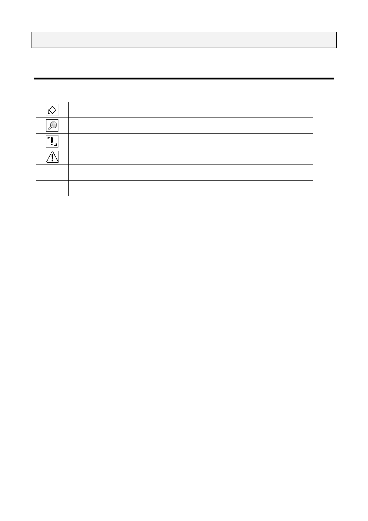
8–1. How to Read This Document
The symbols used in this document and their explanations are shown below.
ndicates a supplementary explanation.
ndicates where to refer to.
ndicates that there is a setting restriction.
ndicates that it must be checked before use.
【 】
ndicates what is stated on the panel of the simulator.
[ ]
ndicates what is shown on the display section of the simulator.
8. INTRODUCTION
17
8–2. Terms and Definitions
Term Definition
EMC
Abbreviation of Electro Magnetic Compatibility. The concept which is
generally required on electronic products and devices as a basic ability to
radiate emission within the limit and to have enough immunity against
external disturbances.
EMC technitian
A person who has enough skill and knowledge in EMC field. n this
manual, this term means especialy a person who understands methods of
ESD immunity testing well.
Protective earth terminal
An exclusively used terminal to ground a part of the electronic product,
such as chassis, etc., where is likely to be touched by a human body, for
preventing an elecric shock in case of internal electic leakage of the
procut.
EUT Equipment Under Test. Equipment to be tested by test equipment.
Electrostatic discharge
(ESD) immunity test
A category of immunity test which simulates electrostatic discharge
phenomnon that a charged human body or object discherges to an
electronic product.
Contact discharge
A method of the ESD immunity testing in which the discharge tip of the
discharge gun is kept in contact with the EUT or coupling plane and the
discharge is actuated by the discharge switch of the s
imulator. t is an
unrealistic phenomenon in nature, but enables the test more reproducible.
Air discharge
A method of the ESD immunity testing in which the discharge tip of the
discharge gun is moved towards the EUT until the tip touches the EUT. t
is closer to natural phenomenon but has an unstable elements since it is
dependet on test enviroment due to discharge in the air.
Discharge gun A part of the simulator including charging and discharging circuit.
One-hand handling is available.
CR unit
A part of the discharge gun equiped a charge capacitor (C) and a
discharge resistor (R). The unit should be exchangeable to change the
constant values of C and R on the circuit accroding to the standard
requirement.
Gun head
A head part of the discharge gun. There are mainly two types, for EC
standard and for SO standard. t should be exchanged accordinf to the
standard.
Discharge tip
Literally a “tip” part of the discharge gun. There are mainly two types, a
conical type for contact discharge and a round type for air discharge.
18
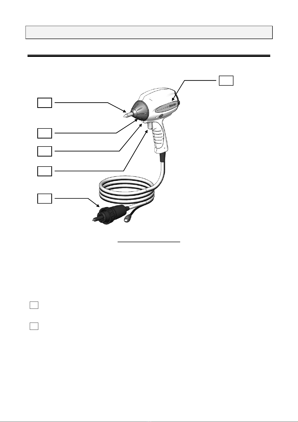
9. NAME AND FUNCTION OF EACH PART
9–1. External Appearance and Descriptions
Figure 9.1
Appearance-1
1 Model number label
ndicates Noiseken’s logo, product name and model number.
2 Discharge tips
Electrode tips used to perform electrostatic discharges.
Use the three types of electrode tips according to what need to be tested.
2
3
4
5
6
1
This manual suits for next models
1
Table of contents
Popular Batteries Charger manuals by other brands

ProMariner
ProMariner ProSport6 PFC Owner's manual and installation guide

Aimsak
Aimsak ALC 3540 manual

Power Fist
Power Fist 8959850 user manual

Alpha ESS
Alpha ESS SMILE-G3-EVCT11 Installation, operation & maintenance manual

Hi-Tec
Hi-Tec X4-80 Instrucion manual

Husky
Husky HSK1084HD User's manual & warranty information


