Intelligent Charging Limited IC48V User manual

IC48V Battery Charger/Analyser
Operator Manual
Doc: DWG1060-12-R3 IC48V Operators manual.odt Page 1 of 58 Copyright Material of Intelligent Charging Limited © 2015
Printed On : 14/06/1
IC48V
BATTERY CHARGER
AND CAPACITY TESTER
OPERATORS MANUAL

IC48V Battery Charger/Analyser
Operator Manual
Table of Contents
1 Manual Revision History............................................................................................................4
2 Equipment Description..............................................................................................................5
2.1 General.............................................................................................................................5
2.1.1 Charging Mo es..........................................................................................................5
2.1.2 Capacity Testing Mo es...............................................................................................6
2.2 Component Parts...............................................................................................................8
2.3 Installation........................................................................................................................8
2.4 Front Panel Controls An In icators....................................................................................9
2.5 Rear Panel Controls An In icators....................................................................................11
3 Cell Monitor Interface..............................................................................................................12
3.1 General............................................................................................................................12
3.2 Charging With The Cell Monitor.........................................................................................12
3.2.1 Constant current charge............................................................................................12
3.3 Discharging With The Cell Monitor.....................................................................................13
3.3.1 Capacity Testing To Target Or Time...........................................................................13
3.3.2 Automatic Cell Balance...............................................................................................13
3.4 Monitor Only Mo e...........................................................................................................13
3.5 Normal Charge or Capacity Test Mo e...............................................................................13
3.6 Cell Monitor Exten e Display Reference...........................................................................13
3.7 Printing Data When Using The Cell Monitor........................................................................14
3.8 Cell Number Reversal.......................................................................................................15
3.9 Cell Monitor Specifications................................................................................................15
4 Equipment Menu Operation.....................................................................................................16
4.1 Main Menu.......................................................................................................................16
4.2 Charging Menu.................................................................................................................17
4.3 Capacity Testing Menu......................................................................................................18
4.4 Library Menu....................................................................................................................19
4.5 Settings Menu..................................................................................................................20
4.6 Cell Monitor Menu............................................................................................................21
4.7 Process Operation Menu...................................................................................................22
5 Connecting A Battery...............................................................................................................23
6 Connecting The Flying Lea Cell Monitor..................................................................................25
7 Connecting The Crown............................................................................................................25
8 Battery Charge Operation........................................................................................................26
8.1 Constant Voltage Charge..................................................................................................26
8.2 Constant Current Charge..................................................................................................27
8.3 Multi-Step Constant Current Charge..................................................................................28
8.4 Constant Current Charge Using Cell Monitor.......................................................................29
8.5 Performing A Charge........................................................................................................30
8.5.1 CHARGE FROM A LIBRARY ENTRY..............................................................................30
8.5.2 CHARGE FROM MANUAL DATA...................................................................................30
8.5.3 CHARGE FROM PREVIOUS DATA................................................................................30
9 Battery Capacity Test or Discharge Operation...........................................................................31
9.1 Capacity Test To 100%....................................................................................................31
Doc: DWG1060-12-R3 IC48V Operators manual.odt Page 2 of 58 Copyright Material of Intelligent Charging Limited © 2015
Printed On : 14/06/1

IC48V Battery Charger/Analyser
Operator Manual
9.2 Capacity Test To Target Voltage........................................................................................32
9.3 Capacity test Using Cell Monitor........................................................................................33
9.4 Automatic Cell Balancing...................................................................................................34
9.5 Full Battery Discharge.......................................................................................................35
9.6 Performing A Capacity Test...............................................................................................36
9.6.1 Capacity Test or Discharge From A Library Entry.........................................................36
9.6.2 Capacity Test or Discharge From Manual Data.............................................................36
9.6.3 Capacity Test or Discharge From Previous Data...........................................................36
10 Creating Or Mo ifying Library Entries.....................................................................................37
10.1 Data Entry Proce ure......................................................................................................37
10.2 Entering Charge Data.....................................................................................................37
10.3 Entering Discharge Data.................................................................................................39
11 Process Mo e........................................................................................................................40
11.1 Overview Of Operation...................................................................................................40
11.2 Process Menu.................................................................................................................40
11.2.1 Renaming a process.................................................................................................41
11.2.2 View or E it A Process.............................................................................................41
11.3 Process Execution...........................................................................................................42
11.4 Process Termination.......................................................................................................42
12 Calibration............................................................................................................................44
12.1 Equipment Require .......................................................................................................44
12.2 Calibration Equipment Connection...................................................................................44
12.3 Check Proce ure............................................................................................................44
12.4 Making Calibration A justment........................................................................................45
12.5 Reviewing Calibration Date.............................................................................................46
13 Miscellaneous Unit Functions..................................................................................................47
13.1 Description Of Stop Co es...............................................................................................47
13.2 Print Or Display Previous Operation Results......................................................................49
13.3 Changing The Date Format An Date Time......................................................................49
13.4 Mo ifying Display Intensity.............................................................................................50
13.5 Printing battery serial number.........................................................................................50
14 Service An Maintenance.......................................................................................................51
14.1 Calibration.....................................................................................................................51
14.2 Cleaning........................................................................................................................51
14.3 Battery Backup...............................................................................................................51
14.4 Printer Care....................................................................................................................52
14.4.1 Door Latch..............................................................................................................52
14.4.2 Paper Fee Button...................................................................................................52
14.4.3 Paper Roll Replacement...........................................................................................53
14.4.4 Ribbon Cartri ge Replacement.................................................................................53
14.4.5 Consumables Available.............................................................................................54
15 Specifications........................................................................................................................55
16 Pro uct Disposal Instructions.................................................................................................57
17 Pro uct Warranty..................................................................................................................58
Doc: DWG1060-12-R3 IC48V Operators manual.odt Page 3 of 58 Copyright Material of Intelligent Charging Limited © 2015
Printed On : 14/06/1

IC48V Battery Charger/Analyser
Operator Manual
1 Manual Revision istory
Rev Date Description
1 17-09-2013 Written from an IC50A manual.
2 21-07-2015 Formatting changes..
3 21-04-2016 Corrected maximum charge current at 12V
Doc: DWG1060-12-R3 IC48V Operators manual.odt Page 4 of 58 Copyright Material of Intelligent Charging Limited © 2015
Printed On : 14/06/1

IC48V Battery Charger/Analyser
Operator Manual
2 Equipment Description
2.1 General
The Battery Charger Analyser is an electronically controlle combine universal battery
charging unit with built in battery analysing (capacity testing) capabilities. It is house
in a metal enclosure esigne for bench mounting. As it is supplie it is esigne to
work on a 240V supply. It can be operate on a 115V supply but it will excee the fuse
rating if use on high charge rates.
Equipment control is via an interactive 253 x 32 ot matrix isplay an ata entry is via
a 16-key keypa . Operating mo es an functions are selecte by the use of a simple
menu system. Access to charging an testing operations is performe by either entry of
eight igit battery library names, repeat of last charge or capacity test or new manual
parameters. During operation the isplay will show the instantaneous values of battery
voltage, current an time elapse through the selecte program.
Process mo es can be create where complete unatten e charging, capacity testing
an final charging can be performe . Up to 6 ifferent charge or capacity test steps can
be create an up to 4 process programs can be store in the unit. Each process step
has an optional elaye start for resting the battery an also each step can soun the
alarm with or without a pause in operation. The process is simply continue by pressing
a key on the keypa .
Battery ata is store internally in the units non-volatile memory. The operator can a
an mo ify this list by entering the etails of the battery to be inclu e on the isplay
an keyboar . Alphanumeric igits, up to a maximum of 8 igits, i entify Battery library
entries
Batteries are connecte to the front of the unit by means of two in ivi ual high current
connectors. Connection to the battery has to be ma e via the appropriate connectors
for that battery. The unit is supplie with M8 ring crimps that must have the
appropriate connector for the battery type being teste fitte .
The IC48V can: -
Charge 12V at 80.0A
Charge 24V batteries at 80.0A
Charge 48v batteries at 40.0A
Capacity Test 12V Batteries at 100.0A
Capacity test 24V batteries at 80.0A
Capacity test 48v batteries at 40.0A
The unit contains a high flow rate fan to extract the heat energy generate internally
when running in capacity test mo e.
2.1.1 Charging Modes
CONSTANT VOLTAGE CHARGE
Doc: DWG1060-12-R3 IC48V Operators manual.odt Page 5 of 58 Copyright Material of Intelligent Charging Limited © 2015
Printed On : 14/06/1

IC48V Battery Charger/Analyser
Operator Manual
Where the battery is charge at a re ucing current when the constant voltage
threshol is met. Parameters for this mo e are maximum charge time, optional
minimum current to stop charge an a current threshol , which can etect a
potentially faulty battery.
CONSTANT CURRENT CHARGE WITH TOP UP CHARGE
Where battery is charge at a constant current until a terminal voltage is met, at
this point it can be charge for an a itional time at a user set current. The
overcharge voltage is set in this mo e to prevent overcharging of the battery.
MULTIPLE STEP CONSTANT CURRENT CHARGE
Up to 4 constant current steps can be implemente for the charge cycle. this
mo e also has an overcharge voltage setting to prevent overcharging of the
battery. Charge current can be set to zero for “rest” perio s between charge
steps.
CONSTANT CURRENT USING CELL MONITOR
In this mo e the battery will be charge at constant current with the charge
switching to the top up charge (if require ) when all the cells reach the target
voltage specifie .
2.1.2 Capacity Testing Modes
CAPACITY TEST TO 100 PERCENT
This mo e will ischarge the battery connecte at the current specifie for the
test uration specifie thus reporting the battery capacity is 100% or more. The
capacity test will be stoppe if the target voltage is reache before the full test
time has elapse . During the capacity test an when it is terminate the isplay
will show the amount the capacity test is complete as a percentage.
CAPACITY TEST TO TARGET VOLTAGE
This mo e will ischarge the battery own to the terminal voltage specifie thus
reporting the actual percentage capacity. The capacity test will be stoppe if the
target threshol voltage is reache before the full test time has elapse . During
the capacity test an when it is terminate the isplay will show the amount the
capacity test is complete as a percentage.
CAPACITY TEST WITH CELL MONITOR
This mo e will ischarge the battery connecte at the current specifie for the
test uration specifie thus reporting the battery capacity is 100% or more. The
capacity test will be stoppe if any cell reache the cell target voltage before the
full test time has elapse . During the capacity test an when it is terminate the
isplay will show the amount the capacity test is complete as a percentage.
AUTOMATIC CELL BALANCE
This mo e is esigne to ischarge the battery own to zero volts, where when
any cell reache zero volts a balancing resistor will automatically be place
across it. When the battery total voltage reache near zero all the remaining
balancing resistors will be applie .
FULL DISCHARGE
Doc: DWG1060-12-R3 IC48V Operators manual.odt Page 6 of 58 Copyright Material of Intelligent Charging Limited © 2015
Printed On : 14/06/1

IC48V Battery Charger/Analyser
Operator Manual
This mo e will o a basic ischarge of the battery at the current specifie for the
time specifie .
The unit can be set so that a pre efine charge or capacity test can be sche ule to start at
up to 99.9h in the future. An if uring this time the power is lost to the unit, such as a power
outage, the unit will continue to count own when the power is restore . Note: If the power
outage resumes after the elapse time has been passe the pre efine charge or capacity test
will not be execute .
The unit contains the software that will allow it to be calibrate by the en user oing away
with the nee to sen the unit to a service centre for perio ic calibration. The re-calibration
process only takes a few minutes an this is one without the nee to access the internals of
the unit.
The printer when fitte allows the operator to print har copies of the charge an test results
upon completion of the test. This report can be use to complement the service sche ule by
provi ing full traceability.
Doc: DWG1060-12-R3 IC48V Operators manual.odt Page 7 of 58 Copyright Material of Intelligent Charging Limited © 2015
Printed On : 14/06/1
IC48V Battery Charger/Analyser
Operator Manual
2.2 Component Parts
Upon receipt of your new battery charger analyser unpack an check that all items are
present in the containing box.
STANDARD ITEMS
One IC48V Battery Charger Analyser
One power cor
One Set (+ve & -ve) stan ar battery lea s.
One paper Copy Operators Manual
Certificate Of Conformity
Calibration Certificate
OPTIONAL ITEMS
Cell Monitor Interface
Cell Monitor Crown (to suit battery specifie ).
Battery specific connectors.
2.3 Installation
The Battery Charger Analyser shoul be mounte on a level surface such as a
workbench or stur y shelf above the batteries with a loa ing weight of at least 50Kg.
The unit shoul be site so that at least 10cm of airspace is available all roun the si es
an top of the unit to allow free movement of air require for cooling.
Doc: DWG1060-12-R3 IC48V Operators manual.odt Page 8 of 58 Copyright Material of Intelligent Charging Limited © 2015
Printed On : 14/06/1
MEM
B63
ON
OFF
I
O
MEM
B63
ON
OFF
I
O
8
5
9 A
6 B
31 2
*
CLR 0#
ENT
C
.
4
7
MB73+ MAIN A CHARGE
7-05-2006 16:30:15 B TEST
C SETTINGS
100.0 mm 100.0 mm
100.0 mm

IC48V Battery Charger/Analyser
Operator Manual
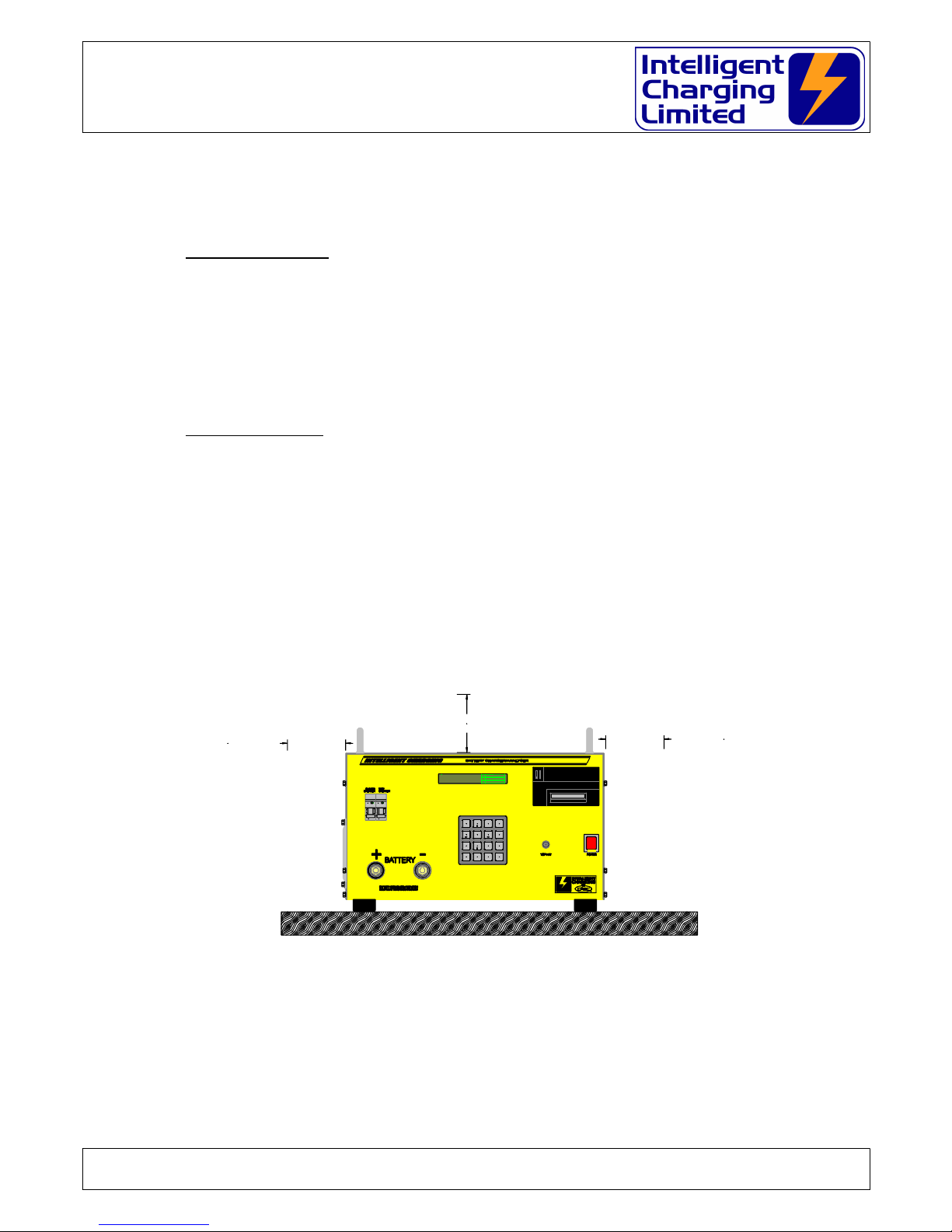
2.4 Front Panel Controls And Indicators
(A) – DISPLAY
All battery charger in ications are ma e on this 256 x 32 ot matrix vacuum fluorescent
isplay.
(B) - BUILT IN PRINTER
If fitte the optional 24 column printer. On the non printer mo els this will be a
blanking plate.
(C) - MAINS POWER SWITCH
Pressing this switch activates mains power. It will illuminate to in icate power is being
applie to the unit.
Doc: DWG1060-12-R3 IC48V Operators manual.odt Page 9 of 58 Copyright Material of Intelligent Charging Limited © 2015
Printed On : 14/06/1
GFEDC
B
A
I
H
J

IC48V Battery Charger/Analyser
Operator Manual
(D) - AUXILLIARY CONNECTOR
This 6 pin connector is the RS232 an power connector for the cell monitoring unit. It
can also be use for remote control operation with PC base software.
(E) – KEYPAD
All battery charge an capacity test functions are activate via this 16 key keypa .
(F) - NEGATIVE BATTERY TERMINAL
Connection of the negative battery lea is ma e to this terminal.
(G) - POSITIVE BATTERY TERMINAL
Connection of the positive battery lea is ma e to this terminal.
(H) - HEAT EXCHANGER EXHAUST FAN
During use the unit absorbs electrical power, which it turns into heat, this fan exit is
where the heat is extracte from the unit. It is important that it is not obstructe .
(I) & (J) - CHARGE & CAPACITY TEST CIRCUIT BREAKERS
The circuit breakers are fitte to prevent high currents from being riven into the
battery or into the unit shoul a fault con ition occur. Always ensure that the circuit
breaker is in the ON position before starting a charge or capacity test.
WARNING
NEVER SWITC T E CIRCUIT BREAK TO ON W EN T E UNIT IS PERFORMING A
C ARGE OR CAPACITY TEST AS SEVERE DAMAGE MAY OCCUR TO T E BATTERY OR T E
EQUIPMENT
ALWAYS PRESS STOP FIRST
If the circuit breaker operates uring a charge imme iately press STOP an remove
power from the unit an isconnect the battery.
Operation of the circuit breaker is an in ication of a fault an the unit will nee to be
checke before using.
Doc: DWG1060-12-R3 IC48V Operators manual.odt Page 10 of 58 Copyright Material of Intelligent Charging Limited © 2015
Printed On : 14/06/1

IC48V Battery Charger/Analyser
Operator Manual
2.5 Rear Panel Controls And Indicators
(K) - Mains Lea
This is the entry point for the power lea into the unit. Always check that the lea is not
amage before use.
(L) - Mains Fuse.
The mains fuse fitte to the IC48V is 16.0A Slow Blow 1¼”
Doc: DWG1060-12-R3 IC48V Operators manual.odt Page 11 of 58 Copyright Material of Intelligent Charging Limited © 2015
Printed On : 14/06/1
MAINS 220V-240V 50Hz/60Hz 2.4KW
REPLACE ONLY WITH SAME TYPE FUSE 13A S/B
SERIAL No:
INTELLIGENT CHARGING
from
ControlledAccess Storage Cabinets Ltd
Ford House, Dewing Road,
RackheathInd. Est. Norwich,
Norfolk, NR13 6PS, ENGLAND.
TEL: +44-1603-722770
FAX: +44-1603-722771
MAIL: sales@casc-ltd.com
C ARGING
INTELLIGENT
FROM
K L

IC48V Battery Charger/Analyser
Operator Manual
3 Cell Monitor Interface
3.1 General
The IC48V battery charger analysers have built in support for the cell-monitoring
interface.
This allows the monitoring of NiC batteries of up to 20 cells. Contact us if cell
monitoring is require above 20 cells.
With the cell-monitoring interface connecte two a itional capacity test options
become available an one a itional charge option.
When the cell monitor is in use two a itional isplays can be selecte by pressing ‘B’
or ‘C’ keys on the keypa while the unit is running. Pressing ‘A’ key will return the
isplay back to the efault isplay.
‘A’ Default isplay.
This is the conventional isplay which all mo es of operation use.
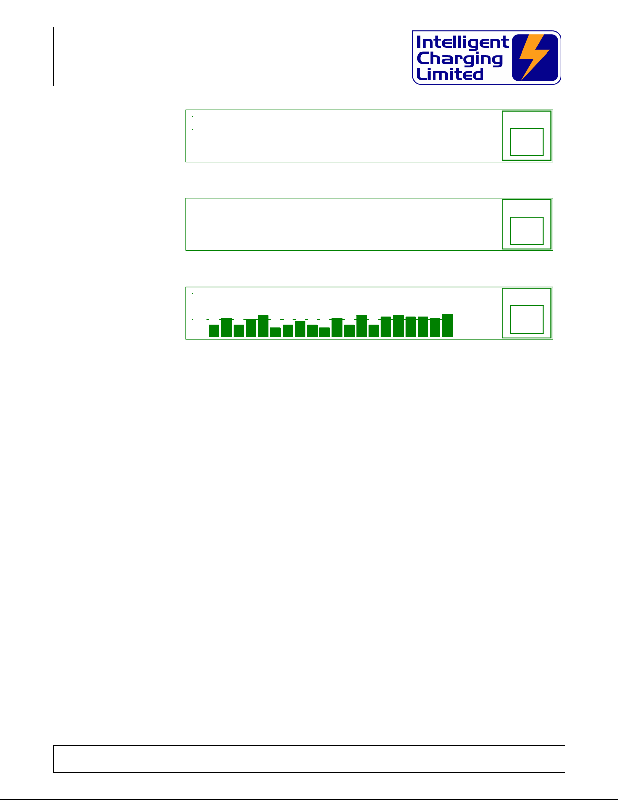
‘B’ A textual list of cell voltages
This isplay will show all 20 cell voltages being measure as a simple list.
‘C’ A graphical bar graph.
This isplay will, show all 20 cell voltages being measure a graphical bar graph,
which will show the inter-relationship between each cell. Also isplaye is a line
representing the target voltage. The battery voltage an charge of capacity test
current highest cell voltage, lowest cell voltage an the "cell focus" voltage are
shown in text format. By using the left an right arrow keys on the keypa a
highlight marker can be move across each cell so that if one particular cell
voltage nee s to be monitore it will be isplaye by the right of the bar graph.
By pressing "0" an either "" or "" keys simultaneously will cause the 1.0V
isplay win ow to be shifte up or own the 2.0V range.
The cell monitor is supplie as an interface unit with 21 patch lea connection for
connecting to batteries via in ivi ual clamps. It has a connector fitte to it where
“crown” assembly can be plugge in. The “crown” arrangement is place onto the top
of the battery with contact to the cells ma e via stainless test pins. The “crown”
arrangement is manufacture to suite one style of battery. If many ifferent styles of
batteries are in use a “crown” will be require for each battery.
3.2 Charging With The Cell Monitor
3.2.1 Constant current charge.
In the constant current charge mo e using the cell monitor interface the charge will
take place at the pre efine constant current until all the cells have reache the target
set point typically 1.55V. At which time the charge rate will change to the a itional
time rate an the charge will continue until the a itional time has elapse . If at any
time uring the charge any cell voltage excee s the cell overcharge voltage typically
1.65V the charge will stop. If a printer is connecte to the unit the cell voltages can be
Doc: DWG1060-12-R3 IC48V Operators manual.odt Page 12 of 58 Copyright Material of Intelligent Charging Limited © 2015
Printed On : 14/06/1

IC48V Battery Charger/Analyser
Operator Manual
printe at pre efine time intervals or can be printe by simply pressing the ‘.’ key. If
a printe report is require at the en of the charge, the final cell voltages will be
inclu e .
3.3 Discharging With The Cell Monitor
3.3.1 Capacity Testing To Target Or Time
This capacity test mo e allows you to ischarge the battery at the require current for
your pre-selecte time until one cell goes below a pre efine target voltage typically
1.00V at which point the ischarge stops an the battery capacity can be seen. If a
printer is connecte to the unit the cell voltages can be printe at pre efine time
intervals or can be printe by simply pressing the ‘.’ key. If a printe report is require
at the en of the capacity test the final cell voltages will be inclu e .
3.3.2 Automatic Cell Balance
This mo e allows you to set a pre efine ischarge current to flatten the battery an to
perform an automatic cell balancing exercise. While uring the ischarge any cell
approaches 0.00V its balancing resistor will be switche in to re uce the reverse charge
effect. When the battery voltage falls below 3.0V an the ischarge current falls below
2.0A the cell-monitoring interface will automatically switch in all the balancing resistors
an will remain it that state until either the CLR key is presse or the Discharge Time
elapses.
3.4 Monitor Only Mode
A mo e of operation is available where the cell monitor interface can be scanne while
the unit is i le. This is obtaine through the SYSTEM menu. While in this mo e the ‘B’
& ‘C’ keys will isplay the textual cell voltages or the bar graph respectively. While this
mo e is active an the printer is installe a snapshot of the cell voltages can be printe
by pressing the ‘.’ key. When accessing the monitor mo e the option of applying the
cell balancing resistors is available, so manual cell balancing can be applie .
3.5 Normal Charge or Capacity Test Mode
When activating the normal charge an capacity test mo es if the unit etects that the
cell monitor is connecte it will ask the operator if cell monitoring is require uring the
operation. If this is selecte the cell monitor will scan the cells an report the voltages
but will take no actions on in ivi ual cell voltages etc.
3.6 Cell Monitor Extended Display Reference
When performing a charge or capacity test the isplay will always efault to showing
the main process con itions, but when the cell monitor is in use there are two
a itional isplays which give the operator a list of cell voltages at the instant in time or
a graphical bar isplay of the cell voltages. The alternative isplays are viewe by
pressing either of the ‘A’, ‘B’ or ‘C’ keys on the keypa .
Doc: DWG1060-12-R3 IC48V Operators manual.odt Page 13 of 58 Copyright Material of Intelligent Charging Limited © 2015
Printed On : 14/06/1
IC48V Battery Charger/Analyser
Operator Manual
The ‘A’ key changes the isplay to the main process con itions as shown:
The ‘B’ key changes the isplay to the full 20-cell voltage list as shown:
The ‘C’ key changes the isplay to a bar graph of cell voltages as shown:
While the graphical isplay is viewe the range of the isplay can be ynamically
change from the efault 0.8 to 1.8V to a bottom limit of 0.0V to 1.0V or an upper limit
of 1.0 to 2.0V by pressing an hol ing the "0" key an pressing the "" or ""
respectively. Each step is an increment or ecrement of 0.1V.
3.7 Printing Data When Using The Cell Monitor
If the printer is fitte to the charger analyser an the cell monitor is in use there are
a itional printing facilities available. When performing a charge or capacity test the cell
voltages can be printe manually at a time to suit you by simply pressing the ‘.’ key or
a print interval can be specifie in minutes. When the cell monitor is in use the full list
of cell voltages will also be inclu e in the final print at the en of the operation. The
cell monitor printout is a similar format to the figure below:
Doc: DWG1060-12-R3 IC48V Operators manual.odt Page 14 of 58 Copyright Material of Intelligent Charging Limited © 2015
Printed On : 14/06/1
STOP
*
CLR
1.. 5 1.35V 1.35V 1.35V 1.35V 1.35V
6..10 1.35V 1.35V 1.35V 1.35V 1.35V
11..15 1.35V 1.35V 1.35V 1.35V 1.35V
16..20 1.35V 1.35V 1.35V 1.35V 1.35V
STOP
*
CLR
1.80
1.20
0.08
26.9V 0.0A
HIGH = 1.36V
LOW = 1.32V
C 01 = 1.32V
T1.55V 1.0A + 1.0A 1.0H O1.65V F 5.0H
27.6V 0.5A 0h00m00
MANUAL 24.0V CELL MONITOR CC CHARGE
STOP
*
CLR

IC48V Battery Charger/Analyser
Operator Manual
3.8 Cell Number Reversal
The cell monitor accessory is marke with cell numbers starting with #1 through to #20
(The maximum number of calls that can be monitore ). Cell #1 is consi ere to be the
cell which is connecte to the negative (-ve) cell en of the battery whereas cell #20
(in a 20 cell battery) is consi ere to be the cell which is connecte to the positive
(+ve) en of the battery.
Many battery manufacturers use the reverse cell numbering where cell #1 is the
positive (+ve) en of the battery an in the case of a 20 cell battery the #20 cell is the
negative.
Because of this numbering technique the battery charger has an option in the cell,
monitor settings to “reverse” the cell numbering for isplay an printing purposes. The
cell isplays show which is +ve en of the battery an which is the negative so that if
the cell numbering is reverse it is shown which way roun the numbering takes.
3.9 Cell Monitor Specifications
Power +5.0V
Cell Voltage Range -2.5V to +2.5V
Max No. Cells 20
Full Scan Rate 5 secon s
Balance Switching current 2.0A
Balance continuous current 1.0A
Balance Resistance 1.0Ω ±1% 2W
Doc: DWG1060-12-R3 IC48V Operators manual.odt Page 15 of 58 Copyright Material of Intelligent Charging Limited © 2015
Printed On : 14/06/1
------------------------
CELL VOLTAGES AT 1.5H
01 1.46V 02 1.46V
03 1.46V 04 1.46V
05 1.46V 06 1.46V
07 1.46V 08 1.46V
09 1.46V 10 1.45V Lo
11 1.46V Hi 12 1.46V
13 1.46V 14 1.46V
15 1.46V 16 1.46V
17 1.46V 18 1.46V
19 1.46V 20 1.46V
------------------------

IC48V Battery Charger/Analyser
Operator Manual
4 Equipment Menu Operation
The Battery Charger Analyser is operate by the use of a simple menu structure which is
accesse by simply pressing the A, B, C or ‘.’ keys. To get back to the main menu the CLR
key is presse repeate ly. The following flowcharts illustrate the menu structure.
4.1 Main Menu
Doc: DWG1060-12-R3 IC48V Operators manual.odt Page 16 of 58 Copyright Material of Intelligent Charging Limited © 2015
Printed On : 14/06/1
THE AIN ENU
SETTINGS ENU
PRINT
SET CLOCK
SYSTE
DISPLAY
A
B
C
DISCHARGE ENU
PREVIOUS
LIBRARY
ANUAL
PROCESS
A
B
C
CHARGE ENU
PREVIOUS
LIBRARY
ANUAL
PROCESS
A
B
C
26 Feb 2009 10:16 o C TP
B73P+ Bat 26.9V
** SERVICEABLE ** LIBRARY
CHARGE
DISCHARGE
SETTINGS
A
B
C
NO DATA
ove
CLR-Abort
ENT-Select
1 NO DATA 2 NO DATA
5 NO DATA
7 NO DATA 8 NO DATA
6 NO DATA
3 NO DATA 4 NO DATA
CM SHOWN WHEN CELL MONITOR IS CONNECTED
TP IS SHOWN WHEN TEMPERATURE PROBE IS CONNECTED

IC48V Battery Charger/Analyser
Operator Manual
4.2 Charging Menu
Doc: DWG1060-12-R3 IC48V Operators manual.odt Page 17 of 58 Copyright Material of Intelligent Charging Limited © 2015
Printed On : 14/06/1
CHARGING IN PROGRESS
CHARGING OPERATIONS
A
ENT
CLR
ENT
CLR
ENT
CLR
ENT
CLR
C16..C20 1.35V 1.35V 1.35V 1.35V 1.35V
STOP
*
CLR
C 1..C 5 1.35V 1.35V 1.35V 1.35V 1.35V
C 6..C10 1.35V 1.35V 1.35V 1.35V 1.35V
C11..C15 1.35V 1.35V 1.35V 1.35V 1.35V
STOP
*
CLR
1.80
1.20
0.08
26.9V 0.0A
HIGH = 1 .36V
LOW = 1.32 V
C 01 = 1 .32V
USE A/B TO CHARGE ODE
CHARGE ODE
CONSTANT VOLTAGE CHARGE
>> NEXT >>
<< PREV <<
ACCEPT
A
B
C
C
CHARGE ENU
PREVIOUS
LIBRARY
ANUAL
PROCESS
A
B
C
CHARGE ODE
CELL ONITOR CC CHARGE
>> NEXT >>
<< PREV <<
ACCEPT
A
B
C
USE A/B TO CHARGE ODE
CHARGE ODE
CONSTANT CURRENT CHARGE
>> NEXT >>
<< PREV <<
ACCEPT
A
B
C
USE A/B TO CHARGE ODE
USE A/B TO CHARGE ODE
CHARGE ODE
ULTI-STEP CHARGE
>> NEXT >>
<< PREV <<
ACCEPT
A
B
C
26 Feb 2009 10:16 o C TP
B73P+ Bat 26.9V
** SERVICEABLE ** LIBRARY
CHARGE
DISCHARGE
SETTINGS
A
B
C
NO DATA
éèêç ove
CLR-Abort
ENT-Select
1 NO DATA 2 NO DATA
5 NO DATA
7 NO DATA 8 NO DATA
6 NO DATA
3 NO DATA 4 NO DATA
Nominal Volts 12.0V Target Volts 13.8V
in 0.0A Rise 0.0A Target Fail 5.0H
HELP LINE APPEARS HERE
Charge Amps 1.0A Charge Time 1.0H
TgFail 24.0H Ochg 1.65V CP 0m
Extra T 1.0H Extra Amps 0.5A
LIBRARY
ANUAL
TI ED
A
B
C
Target 1.55V ax Amps 1.0A
CELL ONITOR CC CHARGE 12.0V
STARTExtra Amps 0.5A For 1.0H Targ Fail 24.0H
Number If Cells 20 Cell Target Volts 1.55V
HELP LINE APPEARS HERE
Charge Amps 1.0A Overcharge Volts 1.65V
Cell Print 0H
Extra Amps 0.5A For 1.0H Targ Fail 24.0H
Nominal Volts 12.0V Target Volts 13.8V
HELP LINE APPEARS HERE
Charge Amps 1.0A Overcharge Volts 15.0V
TgFail 24.0H Overcharge 15.0V
Extra T 1.0H Extra Amps 0.5A
LIBRARY
ANUAL
TI ED
A
B
C
Target 13.8V ax Amps 1.0A
CONSTANT CURRENT CHARGE 12.0V
START
Overcharge Volts 15.0V
3: 1.0A 1.0H 4: 1.0A 1.0H
LIBRARY
ANUAL
TI ED
A
B
C
1: 1.0A 1.0H 2: 1.0A 1.0H
ULTI-STEP CHARGE 12.0V
START
Fail Tm 0.0H Amps Rise 0.0A
Run Tm 1.0H in Amps 0.0A
LIBRARY
ANUAL
TI ED
A
B
C
Target 13.8V ax Amps 1.0A
CONSTANT VOLTAGE CHARGE 12.0V
START
T1.55V 1.0A + 1.0A 1.0H O1.65V F 5.0H
27.6V 0.5A 0h00m00
ANUAL 24.0V CELL ONITOR CC CHARGE STOP
*
CLR
ANUAL 24.0V ULTI-STEP CHARGE
27.6V 0.5A 0h00m00
Step #1 1.0A For 1.0H Overchrg 13.2V STOP
*
CLR
27.6V 0.5A 0h00m00
ANUAL 24.0V CONSTANT CURRENT CHARGE
T13.8V 1.0A + 1.0A 1.0H O13.2V F 5.0H STOP
*
CLR
27.6V 0.5A 0h00m00
ANUAL 24.0V CONSTANT VOLTAGE CHARGE
T 13.8V 1.0A 1.0H 0.0A R0.0AF 5.0H STOP
*
CLR
PRNT
#
ENT
27.6V 0.5A 0h00m00
ANUAL 24.0V STOPPED BY OPERATOR
T1.55V 1.0A + 1.0A 1.0H O1.65V F 5.0H
PRNT
#
ENT
ANUAL 24.0V STOPPED BY OPERATOR
27.6V 0.5A 0h00m00
Step #1 1.0A For 1.0H Overchrg 13.2V
PRNT
#
ENT
27.6V 0.5A 0h00m00
ANUAL 24.0V STOPPED BY OPERATOR
T13.8V 1.0A + 1.0A 1.0H O13.2V F 5.0H
PRNT
#
ENT
27.6V 0.5A 0h00m00
ANUAL 24.0V STOPPED BY OPERATOR
T 13.8V 1.0A 1.0H 0.0A R0.0AF 5.0H
Overcharge Volts 15.0V
Nominal Volts 12.0V Charge Step #4
HELP LINE APPEARS HERE
Charge Amps 1.0A Charge Time 1.0H
B
Delay Before C CC CHARGE : 0.0H
Enter Delayed Start In Hours
Delay Before S CHARGE : 0.0H
Enter Delayed Start In Hours
Delay Before CC CHARGE : 0.0H
Enter Delayed Start In Hours
Delay Before CV CHARGE : 0.0H
Enter Delayed Start In Hours

IC48V Battery Charger/Analyser
Operator Manual
4.3 Capacity Testing Menu
Doc: DWG1060-12-R3 IC48V Operators manual.odt Page 18 of 58 Copyright Material of Intelligent Charging Limited © 2015
Printed On : 14/06/1
CAPACITY TEST IN PROGRESS
CAPACITY TESTING OPERATIONS
A
B
C
27.6V 0.5A 0h 0m 0
ANUAL 24.0V FULL DISCHARGE
Alarm 3.0V Amp 1.0A Tim 1.0H > 0.98H STOP
*
CLR
27.6V 0.5A 0h 0m 0
ANUAL 24.0V AUTO ATIC CELL BALANCE
Balanced 0 Amp 1.0A Tim 1.0H > 0.98H STOP
*
CLR
27.6V 0.5A 0h 0m 0
ANUAL 24.0V CAPACITY TEST CELL ON
Targ 1.00V Amp 1.0A Tim 1.0H > 0.98H STOP
*
CLR
27.6V 0.5A 0h 0m 0
ANUAL 24.0V CAPACITY TEST TO 100%
Targ 1.0V Amp 1.0A Tim 1.0H > 0.98H STOP
*
CLR
27.6V 0.5A 0h 0m 0
ANUAL 24.0V CAPACITY TEST TO TARGET
Targ 1.0V Amp 1.0A Tim 1.0H > 0.98H STOP
*
CLR
A
B
C
ENT
CLR
ENT
CLR
ENT
CLR
ENT
CLR
ENT
CLR
DISCHARGE ODE
FULL DISCHARGE
>> NEXT >>
<< PREV <<
ACCEPT
A
B
C
USE A/B TO CHARGE ODE
27.6V 0.5A 0h 0m 0
ANUAL 24.0V CAPACITY TEST TO 100%
Targ 1.0V Amp 1.0A Tim 1.0H > 0.98H STOP
*
CLR
27.6V 0.5A 0h 0m 0
ANUAL 24.0V CAPACITY TEST TO TARGET
Targ 1.0V Amp 1.0A Tim 1.0H > 0.98H STOP
*
CLR
STOP
*
CLR
1.80
1.20
0.08
26.9V 0.0 A
HIGH = 1. 36V
LOW = 1 .32V
C 01 = 1.32V
STOP
*
CLR
1.. 5 1.35V 1.35V 1.35V 1.35V 1.35V
6..10 1.35V 1.35V 1.35V 1.35V 1.35V
11..15 1.35V 1.35V 1.35V 1.35V 1.35V
16..20 1.35V 1.35V 1.35V 1.35V 1.35V
27.6V 0.5A 0h 0m 0
ANUAL 24.0V CAPACITY TEST CELL ON
Targ 1.00V Amp 1.0A Tim 1.0H > 0.98H STOP
*
CLR
STOP
*
CLR
1.80
1.20
0.08
26.9V 0 .0A
HIGH = 1.36V
LOW = 1.32V
C 01 = 1.32V
STOP
*
CLR
1.. 5 1.35V 1.35V 1.35V 1.35V 1.35V
6..10 1.35V 1.35V 1.35V 1.35V 1.35V
11..15 1.35V 1.35V 1.35V 1.35V 1.35V
16..20 1.35V 1.35V 1.35V 1.35V 1.35V
27.6V 0.5A 0h 0m 0
ANUAL 24.0V AUTO ATIC CELL BALANCE
Balanced 0 Amp 1.0A Tim 1.0H > 0.98H STOP
*
CLR
27.6V 0.5A 0h 0m 0
ANUAL 24.0V FULL DISCHARGE
Alarm 3.0V Amp 1.0A Tim 1.0H > 0.98H STOP
*
CLR
Delay Before FULL DISCHRG : 0.0H
Enter Delayed Start In Hours
Delay Before CELL BALANCE : 0.0H
Enter Delayed Start In Hours
Delay Before CELL CAPTEST : 0.0H
Enter Delayed Start In Hours
Delay Before CAPTEST TARG : 0.0H
Enter Delayed Start In Hours
Delay Before CAPTEST 100% : 0.0H
Enter Delayed Start In Hours
Discharge Time 1.0H
Discharge Amps 1.0A
LIBRARY
ANUAL
TI ED
A
B
C
Alarm Volts 3.0V
FULL DISCHARGE 24.0V
START
LIBRARY
ANUAL
TI ED
A
B
C
AUTO ATIC CELL BALANCE 12.0V
START
Discharge Time 1.0H
Discharge Amps 1.0A
LIBRARY
ANUAL
TI ED
A
B
C
Cell Target Volts 1.00V
CAPACITY TEST CELL ON 12.0V
START
Discharge Time 1.0H CP 0
Discharge Amps 1.0A
LIBRARY
ANUAL
TI ED
A
B
C
Target Volts 10.0V
CAPACITY TEST TO TARGET 12.0V
START
Discharge Time 1.0H
Discharge Amps 1.0A
LIBRARY
ANUAL
TI ED
A
B
C
Target Volts 10.0V
CAPACITY TEST TO 100% 12.0V
START
Discharge Time 1.0H
Discharge Amps 1.0A
Nominal Volts 12.0V Alarm Volts 3.0V
HELP LINE APPEARS HERE
Discharge Amps 1.0A Test Time 1.0H
HELP LINE APPEARS HERE
Number Of Cells 20
Discharge Amps 1.0A Test Time 1.0H
Number Of Cells 20 Cell Target Volts 1.00V
HELP LINE APPEARS HERE
Cell Print Interval 0
Discharge Amps 1.0A Test Time 1.0H
Nominal Volts 12.0V Target Volts 10.0V
HELP LINE APPEARS HERE
Discharge Amps 1.0A Test Time 1.0H
HELP LINE APPEARS HERE
Nominal Volts 12.0V Target Volts 10.0V
Discharge Amps 1.0A Test Time 1.0H
NO DATA
éèêç ove
CLR-Abort
ENT-Select
1 NO DATA 2 NO DATA
5 NO DATA
7 NO DATA 8 NO DATA
6 NO DATA
3 NO DATA 4 NO DATA
DISCHARGE ENU
PREVIOUS
LIBRARY
ANUAL
PROCESS
A
B
C
DISCHARGE ODE
AUTO ATIC CELL BALANCE
>> NEXT >>
<< PREV <<
ACCEPT
A
B
C
USE A/B TO CHARGE ODE
DISCHARGE ODE
CAPACITY TEST CELL ON
>> NEXT >>
<< PREV <<
ACCEPT
A
B
C
USE A/B TO CHARGE ODE
26 Feb 2009 10:16 o C TP
B73P+ Bat 26.9V
** SERVICEABLE ** LIBRARY
CHARGE
DISCHARGE
SETTINGS
A
B
C
DISCHARGE ODE
CAPACITY TEST TO 100%
>> NEXT >>
<< PREV <<
ACCEPT
A
B
C
USE A/B TO CHARGE ODE
DISCHARGE ODE
CAPACITY TEST TO TARGET
>> NEXT >>
<< PREV <<
ACCEPT
A
B
C
USE A/B TO CHARGE ODE

IC48V Battery Charger/Analyser
Operator Manual
4.4 Library Menu
Doc: DWG1060-12-R3 IC48V Operators manual.odt Page 19 of 58 Copyright Material of Intelligent Charging Limited © 2015
Printed On : 14/06/1
LIBRARY MENU
USE A/B TO CHARGE ODE
CHARGE ODE
CONSTANT VOLTAGE CHARGE
>> NEXT >>
<< PREV <<
ACCEPT
A
B
C
CHARGE ODE
CONSTANT CURRENT CHARGE
>> NEXT >>
<< PREV <<
ACCEPT
A
B
C
USE A/B TO CHARGE ODE
USE A/B TO CHARGE ODE
CHARGE ODE
ULTI-STEP CHARGE
>> NEXT >>
<< PREV <<
ACCEPT
A
B
C
CHARGE ODE
CELL ONITOR CC CHARGE
>> NEXT >>
<< PREV <<
ACCEPT
A
B
C
USE A/B TO CHARGE ODE
Extra Amps 0.5A For 1.0H Targ Fail 24.0H
Number If Cells 20 Cell Target Volts 1.55V
HELP LINE APPEARS HERE
Charge Amps 1.0A Overcharge Volts 1.65V
Cell Print 0H
Overcharge Volts 15.0V
Nominal Volts 12.0V Charge Step #4
HELP LINE APPEARS HERE
Charge Amps 1.0A Charge Time 1.0H
Extra Amps 0.5A For 1.0H Targ Fail 24.0H
Nominal Volts 12.0V Target Volts 13.8V
HELP LINE APPEARS HERE
Charge Amps 1.0A Overcharge Volts 15.0V
Nominal Volts 12.0V Target Volts 13.8V
in 0.0A Rise 0.0A Target Fail 5.0H
HELP LINE APPEARS HERE
Charge Amps 1.0A Charge Time 1.0H
DISCHARGE ODE
CAPACITY TEST TO 100%
>> NEXT >>
<< PREV <<
ACCEPT
A
B
C
USE A/B TO CHARGE ODE
DISCHARGE ODE
CAPACITY TEST TO TARGET
>> NEXT >>
<< PREV <<
ACCEPT
A
B
C
USE A/B TO CHARGE ODE
DISCHARGE ODE
CAPACITY TEST CELL ON
>> NEXT >>
<< PREV <<
ACCEPT
A
B
C
USE A/B TO CHARGE ODE
DISCHARGE ODE
AUTO ATIC CELL BALANCE
>> NEXT >>
<< PREV <<
ACCEPT
A
B
C
USE A/B TO CHARGE ODE
DISCHARGE ODE
FULL DISCHARGE
>> NEXT >>
<< PREV <<
ACCEPT
A
B
C
USE A/B TO CHARGE ODE
Nominal Volts 12.0V Alarm Volts 3.0V
HELP LINE APPEARS HERE
Discharge Amps 1.0A Test Time 1.0H
HELP LINE APPEARS HERE
Number Of Cells 20
Discharge Amps 1.0A Test Time 1.0H
Number Of Cells 20 Cell Target Volts 1.00V
HELP LINE APPEARS HERE
Cell Print Interval 0
Discharge Amps 1.0A Test Time 1.0H
Nominal Volts 12.0V Target Volts 10.0V
HELP LINE APPEARS HERE
Discharge Amps 1.0A Test Time 1.0H
HELP LINE APPEARS HERE
Nominal Volts 12.0V Target Volts 10.0V
Discharge Amps 1.0A Test Time 1.0H
26 Feb 2009 10:16 o C TP
B73P+ Bat 26.9V
** SERVICEABLE ** LIBRARY
CHARGE
DISCHARGE
SETTINGS
A
B
C
NO DATA
ove
CLR-Abort
ENT-Select
1 NO DATA 2 NO DATA
5 NO DATA
7 NO DATA 8 NO DATA
6 NO DATA
3 NO DATA 4 NO DATA 1 NO DATA
SAFT 40912
SAFT 40912
CONSTANT VOLTAGE CHARGE
LIBRARY
ODIFY
PRINT
A
B
C
CAPACITY TEST TO 100%
ERASE
ENTER LIBRARY NA E "_ "
HELP LINE APPEARS HERE
PRESS ENT TO CONFIR
ERASING SAFT 40912 [+12.0V] FRO LIBRARY
CAPACITY TEST TO 100%
CONSTANT VOLTAGE CHARGE

IC48V Battery Charger/Analyser
Operator Manual
4.5 Settings Menu
Doc: DWG1060-12-R3 IC48V Operators manual.odt Page 20 of 58 Copyright Material of Intelligent Charging Limited © 2015
Printed On : 14/06/1
ACCESSING THE SETTINGS
26 Feb 2009 10:16 o C TP
B73P+ Bat 26.9V
** SERVICEABLE ** LIBRARY
CHARGE
DISCHARGE
SETTINGS
A
B
C
SETTINGS ENU
PRINT
SET CLOCK
SYSTE
DISPLAY
A
B
C
SYSTE ENU
RESET
CALIBRATE
CONTROL
ORE...
A
B
C
DISPLAY ENU
BATTERY
PREVIOUS
SYSTE
PRINT
A
B
C
PRINT ENU
BATTERY
PREVIOUS
SYSTE
DISPLAY
A
B
C
USE A/B TO CHANG E FOR AT
DATE FOR AT
dd/mm/yyyy
>> NEXT >>
<< PREV <<
ACCEPT
A
B
C
dd/mm/yyyy hh:mm:ss
ENTER DATE & TOD
16/12/2009 10:09:00
CALIBRATE ENU
RESET DATE
ADJUST ENT A
B
C02C-_
ENTER THE UNIT 4-DIGIT SERIAL NU BER
02C-_
ENTER THE UNIT 4-DIGIT SERIAL NU BER
ENTER VOLTAGE READING ON VOLT ETER _0.00V
CONNECT A GOOD 12/24V +40AH BATTERY
ENTER A PS READING ON A P ETER _0.00A
SETTING UP CHARGE A PS
ENTER VOLTAGE READING ON VOLT ETER _0.0V
SETTING UP DISCHARGE ODE
*** UPDATED ***
*** UPDATED ***
ENTER A PS READING ON A P ETER _0.00A
T=FFF 18.53 |TR O/H NOR AL
1-ATST>OFF |3=TR1>OFF |5- UTED |D1=000
V=3CE 10.21 |CH=007 0.00 |CT=007 0.00
2=BTST>OFF |4=TR2>OFF |6=PARALL|D2=000
02C-_
RESETTING OF DEFAULTS
ENTER THE UNIT 4-DIGIT SERIAL NU BER
02C-_
CONTROL DISPLAY : FOR DIAGNOSTIC USE
ENTER THE UNIT 4-DIGIT SERIAL NU BER
AUTHORISED SERVICE PERSONNEL ONLY
UNIT NEEDS RE-CALIBRATION
DONE
*
CLR
DONE
*
CLR
27.6V 0.5A 0h00m00
ANUAL 24.0V CONSTANT CURRENT CHARGE
T13.8V 1.0A + 1.0A 1.0H O13.2V F 5.0H
DONE
*
CLR
Target Volts 10.0V
CAPACITY TEST TO 100% 12.0V
Discharge Time 1.0H
Discharge Amps 1.0A
Run Tm 1.0H in Amps 0.0A
DONE
*
CLR
Fail Tm 0.0H Amps Rise 0.0A
Target 13.8V ax Amps 1.0A
CONSTANT VOLTAGE CHARGE 12.0V
DONE
*
CLR
VSF 0.01049266 L SF 0.00000000 CSF 0.01466274 TSF 0. 01466274
Cell onitor Program SW309 Version 02
Cal 21/12/2009 ***** Serviceable *****
S/N 02C-6137 firmware 4.0 21-12-2009
SYSTE ENU
Batt S/N
CELL ONIT
A
B
C
USE A/B TO CHANGE F OR AT
Request SN ?
no
>> NEXT >>
<< PREV <<
ACCEPT
A
B
C
Table of contents
Other Intelligent Charging Limited Batteries Charger manuals


