Nokia 1508I User manual

1508i(RM-430)
RF Description and Troubleshooting
NokiaCustomerCare
Issue 1
Copyright © 2008 Nokia, All rights reserved
Nokia Customer Care
1508i (RM-430)
Mobile Terminal
RF Description and Troubleshooting

1508i(RM-430)
RF Description and Troubleshooting
NokiaCustomerCare
Issue 1
Copyright © 2008 Nokia, All rights reserved
Contents
1508i RF troubleshooting

1508i(RM-430)
RF Description and Troubleshooting
NokiaCustomerCare
Issue 1
Copyright © 2008 Nokia, All rights reserved
Component Layout
Figure 1 and Figure 2 show the main components of the 1508i mobile terminal.
Figure 1: Component layout (Top)

1508i(RM-430)
RF Description and Troubleshooting
NokiaCustomerCare
Issue 1
Copyright © 2008 Nokia, All rights reserved
Figure 2: Component layout (Bottom)

1508i(RM-430)
RF Description and Troubleshooting
NokiaCustomerCare
Issue 1
Copyright © 2008 Nokia, All rights reserved
Tx Troubleshooting
Tx System Block Diagram
Rx
Figure 3: Tx system block diagram
Tx Introduction
The SA9562 is highly integrated direct conversions transmit IC for use in multi-band
(800MHz, 1700MHz and 1900MHz) mobile phones. It can be used in CDMA modes
conforming to the CDMA2000 1xRTT release A in three frequency bands. Fabricated in
QUBiC4 BiCMOS technology, it integrates an IQ modulator, dual Σ∆ Fractional-N
synthesizers, a semi-integrated crystal oscillator, a fully integrated Transmitter VCO, an RF
VGA for CEL and PCS, one PA driver for the US Cellular band (824 to 849MHz) and two PA
drivers for PCS bands (1750MHz to 1780MHz or 1850MHz to 1910MHz). Figure 3 shows the
RF Tx system block diagram
Main Tx Component
cou
p
ler
Duplexer

1508i(RM-430)
RF Description and Troubleshooting
NokiaCustomerCare
Issue 1
Copyright © 2008 Nokia, All rights reserved
Figure 4: Tx main components
AMS Setup for Tx Troubleshooting
Put PWB on the module jig. Use the following steps to configure AMS for RF troubleshooting.
1. Connect RF connector to a CMU200 or 8960.
2. Connect the PWB to a PC via the Module Jig, and connect a power supply.
3. Open AMS Tools software and select RF Tool.
4. Choose CP Enable, Enable“off”, then send.
5. Choose DSPM AFC Config. Set Pdm Val “0x0200”, then send
6. Choose CP PLL Channel Config. Set Band “PCS”, Channel “600”, then send..
7. Choose CP TX CDMA Test send.
8. Choose DSPM TX AGC Config. Set Hyst State “High gain”, Power (dBm) “24dBm” then send.
9. Choose CP AUX ADC Get. Set TX PCG Sync “off” then send to get Power detector ADC value.

1508i(RM-430)
RF Description and Troubleshooting
NokiaCustomerCare
Issue 1
Copyright © 2008 Nokia, All rights reserved
Figure 5: FTM dialog box (Picture will be updated )
Tx DC Test Points

1508i(RM-430)
RF Description and Troubleshooting
NokiaCustomerCare
Issue 1
Copyright © 2008 Nokia, All rights reserved
Figure 6: Tx DC test point
Table 1 shows the Tx DC test points shown in Figure 6.
Test Point Description Value
1 PA_R1 2.16V for high gain mode,1.6V for low gain mode
2 PA_ON 3.08V for PA turning on, 0V for turning off
3 Tx_on 2.0 V
4 Tx_pll 3.0V
5 Tx_VccIQmod 3.0V
6 TX_AGC 1.92V for 5dBm, 2.16V for 15dBm, 2.4V for 25dBm.
7 Tx IQ in 0.8 V With oscilloscope: 500 mV p-p
8 Tx_vccRFVGA 3.0V
Table 1: Tx DC Test Points

1508i(RM-430)
RF Description and Troubleshooting
NokiaCustomerCare
Issue 1
Copyright © 2008 Nokia, All rights reserved
Tx RF Test Points
Figure 7: Tx RF Test Points
Table 2 shows the test points shown in Figure 7.
Test Point Description Value
1 LO in About 0dBm
2 RFout About 2dBm
3 PA input About 0dBm
4 PA output About 28dBm
5 Coupler output About 26dBm
6 Connector About 24dBm
Table 2: Tx RF Test Points

1508i(RM-430)
RF Description and Troubleshooting
NokiaCustomerCare
Issue 1
Copyright © 2008 Nokia, All rights reserved
Tx Path Troubleshooting
No No No
yes
No
yes
No
yes
No
yes
No No
yes
No
yes
No
yes
No
yes
Notes:
• CBP5.6 is underfilled and can not be replaced.
• The shield case can not be reused after removal.
• After using the heatgun, the domesheet needs to be replaced
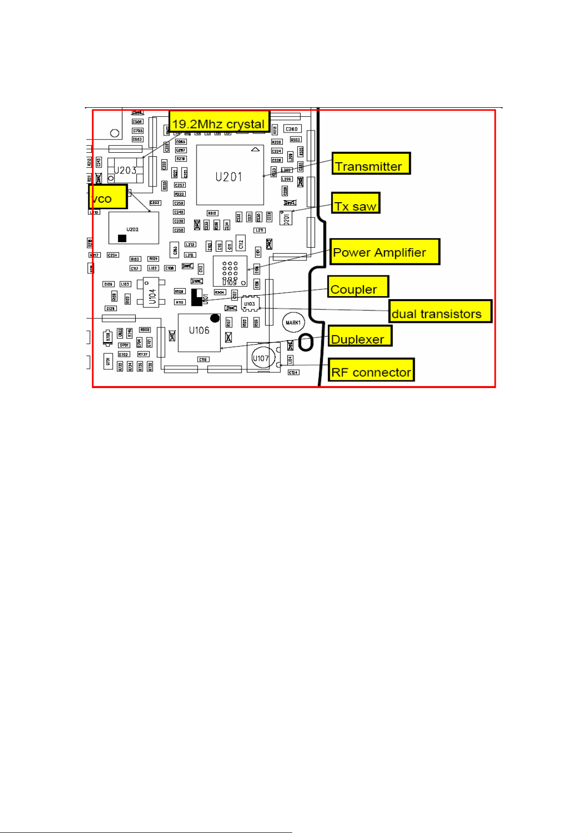
• U109 is PA, it is need special tool to reheat it.
Tx path faults
Measure DC test points
at table 1,is it OK?
Measure Tx RF test point
2 at table 2, is it OK?
Measure Tx RF test point
3 at table 2, is it OK?
Measure Tx RF test point
4 at table 2, is it OK?
Measure Tx RF test point
5 at table 2, is it OK?
If RF antenna feed point pad
obstructed, clean the pad,
connect system simulator to the
MS antenna, is it OK?
Tx troubleshootin
g
finished
Check ACT5805,
CBP5.6
Reheat solder joints of
ACT5805
Measure Tx RF test point
1 at table 2, is it OK? Rehear solder joints of c244
Reheat L205 and reheat SA9562
Reheat the solder joints of C101,D201
Reheat the solder joints of U109 Chan
g
e U109
Reheat the solder
j
oints of C113, U101
Measure Tx RF test point
6 at table 2, is it OK? Reheat the solder
j
oints of R107, U107
Reheat the solder joints of L123, C120
Check antenna module

1508i(RM-430)
RF Description and Troubleshooting
NokiaCustomerCare
Issue 1
Copyright © 2008 Nokia, All rights reserved
Rx Troubleshooting
Rx System Block Diagram
Tx
Figure 9: Rx DC troubleshooting test points
Rx Introduction
The SA9522 is a highly integrated receiver IC based on direct down-conversion (Zero IF)
radio architecture. It can be used in CDMA mode, compliant to the CDMA standards in Band
Class 0 (cellular band) Band Class 1 (US PCS band).And Class 4 (Korean PCS band) also
supports GPS functionality. Due to ZIF architecture of the radio IC the mobile phone design
requires less external passive components and PCB area. It is fabricated using Philips
advanced QuBiC4 BiCMOS technology.
AMS Setup for Rx Troubleshooting
Put PWB on the module jig. Use the following steps to configure AMS for RF RX
troubleshooting.
1. Connect RF connector to CMU200 or 8960.
2. Connect the PWB to a PC via the Module Jig, and connect a power supply.
3. Open AMS Tools software and select RF Tool.
4. Choose CP Enable, Enable“off”, then send.
5. Choose DSPM AFC Config. Set Pdm Val “0x0200”, then send
6. Choose CP PLL Channel Config. Set Band “PCS”, Channel “600”, then send..
7. Choose DSPM Rfc Dagc Set Gain State. Set DAgc Enabled “Disable”, DAgc Gain
State “Gain5”
8. Set the CMU or 8960 at 600 channel, The level set to -96dBm.
9. Choose DSPM Rfc RXTX send which will return the Received Power.
Du
p
le
x
er

1508i(RM-430)
RF Description and Troubleshooting
NokiaCustomerCare
Issue 1
Copyright © 2008 Nokia, All rights reserved
Figure 10: AMS dialog box
PCS Receiver Check from RF to IQ
When the AMS is ready for PCS RX troubleshooting, If the received power of the
DSPM Rfc RXTX is not close to the signal generator which means that there is a problem in
the RX line. First, test the DC points of the RX DC supply lines according to Table3. Then
test the RF trace.
1. Inject a –75 dBm CW signal of 1931.55MHz (i.e. 300kHz offset from 1931.25 MHz ).
2. Measure a 300 kHz tuning on the analyzer. You should see a typical -52 dBm IQ tuning for
CDMA pcs.

1508i(RM-430)
RF Description and Troubleshooting
NokiaCustomerCare
Issue 1
Copyright © 2008 Nokia, All rights reserved
Figure 11: Receiver IQ level on CDMA pcs band
Figure 12 shows the PCS spectrum with an inject tone at -75 dBm, as well as the IQ output
test points. Note that DC is present on the IQ output test points. All test points should be
approximately equal.
Figure 12: Pcs spectrum (left) and IQ output test points (right) (Picture will be updated )

1508i(RM-430)
RF Description and Troubleshooting
NokiaCustomerCare
Issue 1
Copyright © 2008 Nokia, All rights reserved
Receiver DC Test Points
Figure 13: Rx DC troubleshooting test points
Table 4 includes the descriptions and values for Rx DC troubleshooting test
points shown in Figure 13.
Table 4: Rx DC Test Points
Test Point Description Value
1 VCCBIAS Test C319, 3.0V
2 VCCMX Test C324, 3.0V
3 VCCBB Test C323, 3.0V
4 VCCDD Test c322, 3.0V
5 VDDP Test C334, 3.0V

1508i(RM-430)
RF Description and Troubleshooting
NokiaCustomerCare
Issue 1
Copyright © 2008 Nokia, All rights reserved
Receiver RF Test Points
For the test points in Figure 14, an external signal source of –96 dBm was added to the RF
input. Set LNA GAIN STATE = 4.The signal was then traced throughout the receiver chains.
An Agilent8960 call box is recommended. Set the band and channel as ETS set. Set the cell
power = - 96dBm. Watch the received power of the DSPM Rfc RXTX. Measurements were
taken with the RF Probe. Signal levels are approximate, and the accuracy may be +/- 2 dB or
more depending on the probe position and grounding.
Figure 14: Receiver RF troubleshooting test points

1508i(RM-430)
RF Description and Troubleshooting
NokiaCustomerCare
Issue 1
Copyright © 2008 Nokia, All rights reserved
Table 5 includes the descriptions and values for Rx RF troubleshooting test points
shown in Figure 14.
Test Point Description Value
1 LNA IN About -96dBm
2 LNA_OUT About -80dBm
3 RX SAW OUTPUT1 About -82dBm
4 RX SAW OUTPUT2 About -82dBm
5 RX_QP
6 RX_QN
7 RX_IP
8 RX_IN
9 RX LO IN -3dB
Table 5: Rx RF Test Points

1508i(RM-430)
RF Description and Troubleshooting
NokiaCustomer
Care
Issue 1
Copyright © 2008 Nokia, All rights reserved
Rx Path Troubleshooting
No No
Yes
No
Yes
No
Yes
No
Yes
No
Yes
No
Yes
Note:
• CBP5.6 is underfilled and can not be replaced.
• The Shielding Case Assy can not be reused after removal.
• After using the heatgun, the domesheet needs to be replaced
Rx path faults
Measure DC test points at
table 4, is it OK?
Measure Rx RF test points
1 at table 5, is it OK?
Measure Rx RF test points
2bl
iiOK?
Measure Rx RF test points
3 ,4 at table 5, is it OK?
Connect System
Change U202
Reheat solders joints of
D301
Reheat solder joints of
C316
Reheat solder joints of
C320
Check U1001(ACT5808) Reheat solder joints of
Measure Rx RF test points
5,6,7,8 at table 5,is it OK?
Change U301
Measure RX RF test points
9 at table5, is it ok?
Check antenna module
Other manuals for 1508I
5
This manual suits for next models
1
Table of contents
Other Nokia Cell Phone manuals

Nokia
Nokia 7110 - Cell Phone - GSM User manual

Nokia
Nokia Lumia 620 User manual

Nokia
Nokia 002J3X4 User manual

Nokia
Nokia 8210 User manual

Nokia
Nokia 3710a-1 User manual

Nokia
Nokia 220 User manual

Nokia
Nokia HANDSET 6280 User manual

Nokia
Nokia 3560 - Cell Phone - AMPS User manual

Nokia
Nokia 105 4G 2021 User manual

Nokia
Nokia RH-92 User manual