Nokia Customer Care Antenna Description and Troubleshooting
6235/6235i/6236i (RM-60)
Issue 1 04/2005 ©2005 Nokia Corporation Company Confidential Page 9
Calibration Factor for PCS1900 Frequency
Use a call box to turn on the transmitter of the mobile terminal with a known output
power and antenna performance at the maximum output power (all bits up). Measure
the transmitted power on the RF connector and through a coupler at CDMA PCS channel
1175. Use the difference between the transmitted and received powers as the calibration
number (path loss on Cell band including coupler, cable, and attenuator path losses) for
the coupler on Cell band.
The nominal value for power measured at the RF connector is 23 dBm. The coupler path
loss is normally ~17…18 dB at the PCS band. If a 10 dB attenuator and a cable with
~1 dB loss is used, the total path loss is 28 to 29 dB and the measured power should be
from -5 to -6 dBm [23 dBm - (28…29 dB)]. However, path loss has to be measured
separately for every coupler because path losses vary depending on the setup, cables, and
attenuator.
Measurement Procedure for Cell800/PCS1900 Mobile Terminals
1. Place the mobile terminal with the display up in the test adapter (DA-54).
2. Turn on the mobile terminal's transmitter at the PCS band on CDMA mode
channel 1175 at maximum output power (nominal 23 dBm at RF connector).
3. Measure the RF power with a CPL-8 coupler. This represents the internal antenna
to RF coupler measurement.
4. Turn the mobile terminal's transmitter off.
The CDMA antenna test fails if the measured power is outside the test limits.
Testing GPS Antenna
Calibration Factor for GPS
In GPS test mode 3, the GPS receiver is fed with a CW signal. The GPS receiver should
report C/No ratio of 35 dBHz with a -110 dBm signal level on the RF connector
(-110 dBm + cable loss) at signal generator output. The reported C/No figure is recorded
with the signal fed to the RF connector. The C/No value is read with a coupler engaged.
Increase the GPS signal level until the same C/No value is recorded. Use the difference
between the CW signal levels at the generator as the calibration number (path loss on
GPS band including coupler, cable, and attenuator losses).
The nominal coupler path loss at GPS band is 14 to 17 dB. If you use a 10 dB attenuator
and cable with 1 dB loss, the total path loss is 25 to 28 dB. The signal level at generator
output must be -85 to -82 dBm [-110 dBm -(-25 dB to -28 dB)]. However, the path loss
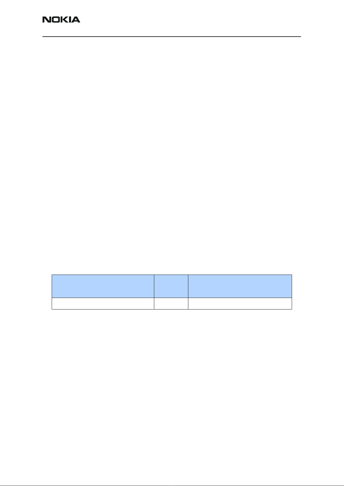
Table 1: CDMA Measurement Test Limits
Min Measured Power + Coupler,
Cable and Attenuator Path Loss Nominal Max Measured Power + Coupler,
Cable and Attenuator Path Loss
20,0 dBm 23 dBm 26,0 dBm