Nokia 6275 Guide

Nokia Customer Care
6275/6275i (RM-154)
Mobile Terminals
Issue 1 - September 2006 Company Confidential
Antenna Description and
Troubleshooting

6275/6275i (RM-154)
Antenna Description and Troubleshooting Nokia Customer Care
Page 2 Company Confidential Issue 1 - September 2006
Contents Page
Introduction ..................................................................................................................................................... 3
CDMA Antenna on the E-Cover Assembly............................................................................................... 4
Damaged CDMA Radiator Bezel Assembly ...........................................................................................4
Missing or Damaged CDMA Antenna and IHF Pogo Pins ................................................................4
IHF Module ....................................................................................................................................................5
Obstructed RF Feed and Ground Pads ...................................................................................................5
Damaged RF Connector .............................................................................................................................5
Auxiliary Antennas: GPS, BT, and FM ....................................................................................................... 8
GPS Antenna .................................................................................................................................................8
Bluetooth Antenna ......................................................................................................................................9
FM Antenna ...................................................................................................................................................9
Circuit Diagrams and Chip Locations ..................................................................................................10
SAR Reduction Foil...................................................................................................................................... 13

Nokia Customer Care Antenna Description and Troubleshooting
6275/6275i (RM-154)
Issue 1 - September 2006 Company Confidential Page 3
Introduction
This troubleshooting guide addresses potential failures that affect antenna performance
of the 6275/6275i mobile terminals and discusses methods for correction of these
failures. Following are the three serviceable antennas used in the 6275/6275i mobile
terminals:
• CDMA antenna (on the E-cover assembly)
• GPS antenna (on the antenna module)
• Bluetooth antenna (on the D-cover assembly)
The following sections describe these antennas and their connections to the mobile
terminal components.

6275/6275i (RM-154)
Antenna Description and Troubleshooting Nokia Customer Care
Page 4 Company Confidential Issue 1 - September 2006
CDMA Antenna on the E-Cover Assembly
The E-cover (or antenna cover assembly) is comprised of the E-cover plastic part, the
CDMA antenna (or CDMA radiator) and the bezel assembly. The bezel assembly includes
the camera, flash windows, and the bezel.
The E-cover connects to the D-cover assembly via six tabs located on the four corners
and top edge of the E-cover, as well as a snap-in feature located on the bottom two
corners.
Figure 1: CDMA antenna on the E-cover
Damaged CDMA Radiator Bezel Assembly
The CDMA flex radiator antenna and bezel assembly are glued to the inside surface of
the E-cover. To remove the E-cover assembly from the D-cover, use the SRT-6 opening
tool to release the two snap-in tabs that secure the E-cover to the D-cover.
If either the CDMA radiator or bezel assembly is damaged, replace the E-cover assembly.
Note: You cannot replace the CDMA radiator or the bezel individually. You must
replace the entire E-cover assembly.
To reattach the E-cover assembly to the D-cover, align the E-cover above the D-cover
and apply a vertical force to engage the snap-in feature.
Missing or Damaged CDMA Antenna and IHF Pogo Pins
The CDMA antenna is connected to the PWB through two pogo pins. The CDMA antenna
pogo pins are housed in the D-cover (see Figure 1 on page 4).
If a CDMA antenna pogo pin is damaged or missing, replace the D-cover. An improper
connection between the CDMA antenna and the PWB due to a damaged or missing pogo
pin degrades the CDMA antenna performance by 5dB to more than 15dB.
Antenna pogo pins
Ground pin
Feed pin
E-cover assembly

Nokia Customer Care Antenna Description and Troubleshooting
6275/6275i (RM-154)
Issue 1 - September 2006 Company Confidential Page 5
IHF Module
The IHF module impacts the CDMA antenna performance. If there is any damage to the
IHF module, replace the acoustic module.
Figure 2: IHF module
Obstructed RF Feed and Ground Pads
The CDMA antenna ground and feed pogo pins touch the PWB on ground and feed pads.
• If the main antenna feed pad is obstructed, removed, or covered, the CDMA
antenna feed pogo pin does not touch the PWB and the antenna gain degrades
by more than 15 dB.
• If the CDMA antenna ground pad is obstructed, removed, or covered, the ground
pogo pin does not touch the PWB and the antenna gain degrades by more than
5dB.
• If corrosion is present or the pads are missing, replace the PWB.
• If either pad is obstructed or covered, clear or clean the pads.
• If the CDMA antenna matching network is missing or damaged, replace the
component.
• If the PWB is permanently damaged, replace the PWB.
Damaged RF Connector
The CDMA RF connector could fail by not connecting the RF input to the RF output of
the RF connector. If this happens, the antenna gain degrades by about 15dB. You can
check this by testing for DC conductivity between the RF connector’s RF input and
output.
GPS Antenna
Flex Strip on
side of IHF

6275/6275i (RM-154)
Antenna Description and Troubleshooting Nokia Customer Care
Page 6 Company Confidential Issue 1 - September 2006
Perform the DC conductivity test without a cable attached to the RF connector. Because
the RF connector is also a switch, the RF output disconnects from the RF input when a
cable is inserted into the RF connector. When a cable is not inserted, the RF input is
connected to the RF output of RF connector.
• CDMA RF input – connects to the duplexer
• CDMA RF output – connects to the antenna pad through vias
• RF connector – connects to a coaxial cable
If the RF input is not connected properly to the RF output, replace the RF connector.
Figure 3: Main PWB - bottom side
Figure 4: Main PWB - top side
Ground pad
Feed pad
CDMA antenna
matching network
RF connector
GPS pogo pins
Flash pogo pins
RF connector

Nokia Customer Care Antenna Description and Troubleshooting
6275/6275i (RM-154)
Issue 1 - September 2006 Company Confidential Page 7
Figure 5: CDMA antenna matching network schematics

6275/6275i (RM-154)
Antenna Description and Troubleshooting Nokia Customer Care
Page 8 Company Confidential Issue 1 - September 2006
Auxiliary Antennas: GPS, BT, and FM
See the Disassembly chapter for instructions about disassembling the mobile terminal for
auxiliary antenna troubleshooting.
GPS Antenna
The GPS antenna is a printed trace on a flex that adheres to the plastic audio module.
The GPS antenna connects to two pogo pins that are soldered to the PWB. The GPS flex
wraps around the side of the plastic audio module and ends near the audio port at the
top end of the module. Use an RF connector to test the GPS RF components directly.
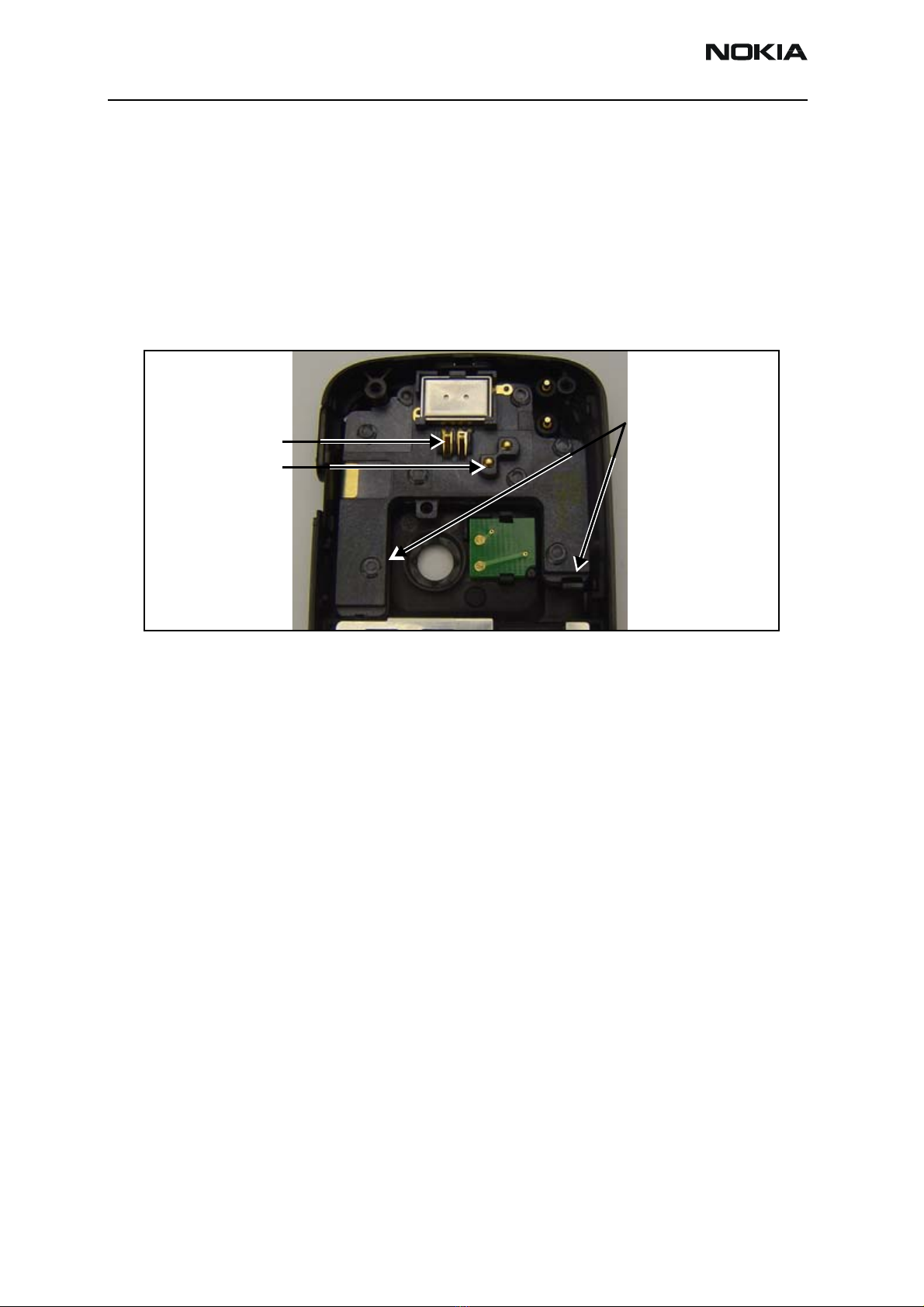
Figure 6: Remove the audio module from the D-cover
The GPS antenna system has the following possible failure modes:
• If the solder bridge of the two GPS pogo-pin pads are dirty, remove and clean the
bridge.
• If the GPS SMD pogo pins are misaligned, properly align and solder them.
• If the GPS SMD pogo pins do not operate freely or easily in their sleeves, replace
them.
• If the wrong pogo pins are soldered at the GPS SMD pogo-pin location, use the
proper GPS pogo pins.
Note that the Flash pogo pins are 5.5mm high, while the GPS SMD pogo pins
are 3.8mm high. (See Figure 3 on page 6.)
• If the GPS SMD pogo pins are improperly soldered to their pads (e.g., cold solder
joint, cracked solder joint, insufficient solder, excessive solder causing tilting),
properly align and solder them.
• If the GPS flex antenna (see Figure 2 on page 5) shows damage to the pogo-pin
pad (pressure tearing, hole, cracking, corrosion, bubbles, etc.) replace the GPS/
audio module.
• If the GPS flex antenna shows damage to the flex (e.g., tearing, cracking,
corrosion, bubble, etc.), replace the GPS/audio module.
Use the SRT-6 opening
tool to remove the audio
module at these locations
IHF contact pins
Earpiece contact pins

Nokia Customer Care Antenna Description and Troubleshooting
6275/6275i (RM-154)
Issue 1 - September 2006 Company Confidential Page 9
• If the GPS flex antenna shows damage to the audio outer gasket or screen (e.g.,
permanently creased, indented, torn, dislodged, distorted, or pressed to the side,
abnormal shape, texture, coloration), replace the GPS/audio module.
• If the GPS flex antenna trace shows damage or contamination (e.g., cracking,
discoloration, corrosion, bubble.), replace the GPS/audio module.
• If the GPS cellular RF connector is defective, replace the RF connector and make
sure the orientation is correct.
Bluetooth Antenna
The bluetooth (BT) antenna is a stamped metal sheet formed with one spring contact and
heat-staked ultrasonically to the D-cover.
Figure 7: Bluetooth antenna
A 0.5pf shunt capacitor was used for antenna impedance matching on the main PWB.
Figure 8: Bluetooth matching component on the main PWB
The BT antenna system has following possible failure modes:
• If the BT antenna spring clip is deformed, replace the D-cover.
• If the BT antenna plastic heat stakes do not hold the metal antenna firmly,
replace the D-cover.
• If the D-cover is deformed or broken, replace the D-cover.
• If the antenna match component is broken, replace the match component.
FM Antenna
The FM-antenna uses the connection through the universal headset jack (UHJ) or the
Pop-port connector to a headset to create an FM antenna of reasonable gain. If the FM
antenna is not working, the chips, UHJ connector, or the Pop-port connector could be
bad.

6275/6275i (RM-154)
Antenna Description and Troubleshooting Nokia Customer Care
Page 10 Company Confidential Issue 1 - September 2006
The FM antenna system has following possible failure modes:
• If the chip components are bad, replace them.
• If the UHJ or Pop-port connector is bad, replace connector.
• If the headset is bad, replace it.
Circuit Diagrams and Chip Locations
Figure 9: Matching chips for the UHJ on the audio schematic
Figure 10: Matching chips for the UHJ on the top PWB component layout

Nokia Customer Care Antenna Description and Troubleshooting
6275/6275i (RM-154)
Issue 1 - September 2006 Company Confidential Page 11
Figure 11: Matching chips for the Pop-port connector on the system connector schematic
Figure 12: Matching chips for the Pop-port connector on the top PWB component layout

6275/6275i (RM-154)
Antenna Description and Troubleshooting Nokia Customer Care
Page 12 Company Confidential Issue 1 - September 2006
Figure 13: Bluetooth matching chips on the bottom PWB component layout

Nokia Customer Care Antenna Description and Troubleshooting
6275/6275i (RM-154)
Issue 1 - September 2006 Company Confidential Page 13
SAR Reduction Foil
The SAR reduction feature uses three A-cover grounds through three clips on the
C-cover. A-cover grounding impacts the radiation performance of the mobile terminal.
If the clips of C-cover are not touching the PWB or A cover, are corroded, or are
obstructed, replace the C-cover.
Figure 14: SAR reduction A-cover (left) and C-cover (right) grounding clip locations

6275/6275i (RM-154)
Antenna Description and Troubleshooting Nokia Customer Care
Page 14 Company Confidential Issue 1 - September 2006
This page intentionally left blank.
Other manuals for 6275
7
This manual suits for next models
2
Table of contents
Other Nokia Cell Phone manuals

Nokia
Nokia 3100 User manual

Nokia
Nokia 1221 - Cell Phone - AMPS User manual

Nokia
Nokia 225 User manual

Nokia
Nokia 1220 User manual

Nokia
Nokia 6720 classic Quick start guide

Nokia
Nokia 1508 User manual

Nokia
Nokia E63 User manual

Nokia
Nokia 1280 User manual

Nokia
Nokia Nuron User manual

Nokia
Nokia 6590i User manual