Norbord CSS 856 User manual

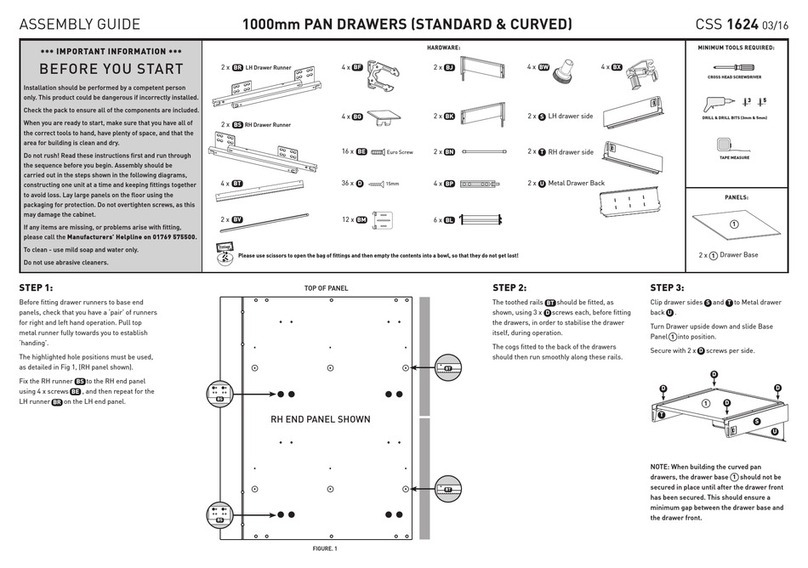
Fit shelf support rails
using 3 x screws per rail.
Insert as shown (16 positions). It's IMPORTANT
that arrow points to outside edge.
Prepare the end panels (supplied
separately) by inserting and
as shown for
both panels.
1 x Top Panel
1 x Base Panel
2 x Fixed Shelf
2 x Shelf Support Rails
2 x Adjustable Shelves
2 x End Panels
2 x Back Panels
1
66
2
1
3
2
4
4
7
7
5
5
5
6
7
Panels
Notes
Hardware Tools required
15mm
25mm
16 x
32 x
2 x
12 x
8 x
A
16 x
H
B
R
G
E
D30mm
6 x
1
6
2
H
H
H
H
H
H
H
H
H
3
H
H
H
3
H
H
H
H
1
2
GAG
A
A
A
G
6
6
G
Apply a small
droplet of glue
to hole before
inserting
900 Aperture
Oven Housing
600 Aperture
Oven Housing
Fridge Freezer
Housing
600mm WIDE
TALL
Oven/Fridge
Freezer Housing
3
3
To build a 900mm high oven housing:
Now affix your cabinet legs
Prior to standing unit upright, fit metal bracing
bars using 4 x screws per bracing bar
to rear of cabinet. Ensure these bracing bars
are fitted at positions that are clear of back of
the fridge appliance.
X
5
Now affix your cabinet legs
X
2 x
Connect base panel onto end panel as shown.
Repeat for top panel and
fixed shelves
3
26
H
H
2
1
6
3
1
3
3
Slide both back panels (supplied
separately) into grooves.
Note: the back panels will require
trimming to the correct height
behind the fixed shelves. Ensure
clear opening behind the oven
section in the centre.
Tighten clockwise
in 8 positions.
H
6
1
5
4
H
6
H
Run small
bead of glue
along all
grooves
2
3
7
7
3
Connect the second end panel as shown,
tighten clockwise in 8 positions.
H
6
H
6
1
H
23
7
3
6
5On back of cabinet, carefully drill through panel
into the edge of fixed shelf
and secure using
2 x screws.
6
7
4
5
2
3
6
4
D
D
D
3
B
B
3mm
2
H
Insert as shown (8 positions). It's IMPORTANT
that arrow points to outside edge.
H
H
H
H
H
H
H
H
4
2
H
H
H
1
Connect base panel and top panel onto
end panel , . Tighten clockwise
in 4 positions.
3
2
6H
1
H
2
6
1
H
2
6
61
Connect end panel as shown.
Tighten clockwise in
remaining 4 positions.
H
6
4
D
Note: End panels and
back panels are
purchased separately
from this shelf pack
A
G
Prepare the end panels (supplied
separately) by inserting and
as shown for
both panels.
Now follow Steps 2 to 6 above, as for the 900mm high
oven housing.
Note: that the position of the fixed shelves and so the
points at which you cut the back panels will differ from the
illustrations for the 900 housing, otherwise the construction
sequence is the same.
1
6
To build a 600mm high oven housing:
A
G
GAGAG
GAGAGGAGAG
Top edge of panels
GAG
AG
6
6
GAGAG
GAGAGGAGAG
Top edge of panels
G
Apply a small
droplet of glue
to hole before
inserting
Push shelf support
into chosen shelf
position holes,
4 per shelf.
Tilt and
slide in
shelf.
To fit shelves
Joining and Levelling
of Cabinets
Fitting to wall
Drill 3mm pilot hole.
Fix bracket
with screw.
B
F
Use appropriate fittings to secure
cabinet to wall (depending on
wall type).
All legs are pre-set
at 150mm height.
Rotate to adjust up
and down, to level the
unit.
3
R
3mm
900
F
Mark 20mm on a 3mm
dia. drill bit with
masking tape. Drill
between the 2 holes
drilled for the hinges,
through one cabinet
side (16mm) and
4mm into the next,
stopping when you reach
the marker. Join the
cabinets together with
2 x screws.
R
E
Prepare the end panels (supplied
separately) by inserting and
as shown for
both panels.
1
6
To build a 50/50 or a 60/40 tall fridge freezer housing:
A
G
GAG
AG
6
6
GAGAG
GAGAGGAGAG
Top edge of panels
G
Apply a small
droplet of glue
to hole before
inserting
G
A
A
A
AA
A
A
A
A
AA
A
A
A
A
ASSEMBLY GUIDE
2 x
F
CSS856 06/10
CSS856 06/10
Insert door hinge into
recess in door and affix
using 2x screws.
Door hinges (standard doors only)
Turn screw as shown, to adjust the door position
B
N
Separate hinge from hinge plate if supplied attached.
Connect door hinge to cabinet
and tighten screw shown.
Affix hinge plate to cabinet using
pre-drilled holes with
pre-mounted screws.
After adjustment is complete
apply cover plate
IM
Edge of panel
Hinges
4 x I4 x N
4 x M
Legs
B
(standard doors only)
If you have chosen framed doors, refer to the instructions supplied in the
separate hinge pack for frame fixing, fitting and adjustment of hinges.
Before you start . . .
WARNING: Installation should be performed by a competent person only. This product could be dangerous if incorrectly installed. Check the pack and
make sure all the components are included - if not, call the Manufacturers' Helpline on 01769 575500 and their team will get things sorted. When you are
ready to start make sure you have the right tools to hand, plenty of space and a clean dry area for building. Don't rush, read the instructions first and run
through the sequence before you begin. Assembly should be done in the stages shown in the following diagrams, constructing one unit at a time and
keeping fittings together to avoid loss. Lay large panels on the floor using the packaging for protection. Do not over tighten screws.
Cleaning - Use mild soap and water only. Do not use abrasive cleaners.
To protect your kitchen doors from any excess heat emitted by your oven, it is strongly recommended that an appropriate Oven Heat Deflector Kit is fitted
around the oven aperture in this unit. Suitable kits are available from B&Q and details can be found in the kitchen price list.
Video assembly guides can be viewed at www.mycabinetguide.co.uk
G
A
G
A
Cross Head Screwdriver
Drill & Drill Bits
To construct
cabinets & legs
3mm
To fit
handles
4.5mm
PVA Wood Glue
Pliers x 2
Hammer
Spirit Level
4 x O4 x Q2 x P
2 x S

Fit shelf support rails
using 3 x screws per rail.
Insert as shown (16 positions). It's IMPORTANT
that arrow points to outside edge.
Prepare the end panels (supplied
separately) by inserting and
as shown for
both panels.
1 x Top Panel
1 x Base Panel
2 x Fixed Shelf
2 x Shelf Support Rails
2 x Adjustable Shelves
2 x End Panels
2 x Back Panels
1
66
2
1
3
2
4
4
7
7
5
5
5
6
7
Panels
Notes
Hardware Tools required
15mm
25mm
16 x
32 x
2 x
12 x
8 x
A
16 x
H
B
R
G
E
D30mm
6 x
1
6
2
H
H
H
H
H
H
H
H
H
3
H
H
H
3
H
H
H
H
1
2
GAG
A
A
A
G
6
6
G
Apply a small
droplet of glue
to hole before
inserting
900 Aperture
Oven Housing
600 Aperture
Oven Housing
Fridge Freezer
Housing
600mm WIDE
TALL
Oven/Fridge
Freezer Housing
3
3
To build a 900mm high oven housing:
Now affix your cabinet legs
Prior to standing unit upright, fit metal bracing
bars using 4 x screws per bracing bar
to rear of cabinet. Ensure these bracing bars
are fitted at positions that are clear of back of
the fridge appliance.
X
5
Now affix your cabinet legs
X
2 x
Connect base panel onto end panel as shown.
Repeat for top panel and
fixed shelves
3
26
H
H
2
1
6
3
1
3
3
Slide both back panels (supplied
separately) into grooves.
Note: the back panels will require
trimming to the correct height
behind the fixed shelves. Ensure
clear opening behind the oven
section in the centre.
Tighten clockwise
in 8 positions.
H
6
1
5
4
H
6
H
Run small
bead of glue
along all
grooves
2
3
7
7
3
Connect the second end panel as shown,
tighten clockwise in 8 positions.
H
6
H
6
1
H
23
7
3
6
5On back of cabinet, carefully drill through panel
into the edge of fixed shelf
and secure using
2 x screws.
6
7
4
5
2
3
6
4
D
D
D
3
BB
3mm
2
H
Insert as shown (8 positions). It's IMPORTANT
that arrow points to outside edge.
H
H
H
H
H
H
H
H
4
2
H
H
H
1
Connect base panel and top panel onto
end panel , . Tighten clockwise
in 4 positions.
3
2
6H
1
H
2
6
1
H
2
6
61
Connect end panel as shown.
Tighten clockwise in
remaining 4 positions.
H
6
4
D
Note: End panels and
back panels are
purchased separately
from this shelf pack
A
G
Prepare the end panels (supplied
separately) by inserting and
as shown for
both panels.
Now follow Steps 2 to 6 above, as for the 900mm high
oven housing.
Note: that the position of the fixed shelves and so the
points at which you cut the back panels will differ from the
illustrations for the 900 housing, otherwise the construction
sequence is the same.
1
6
To build a 600mm high oven housing:
A
G
GAGAG
GAGAGGAGAG
Top edge of panels
GAG
AG
6
6
GAGAG
GAGAGGAGAG
Top edge of panels
G
Apply a small
droplet of glue
to hole before
inserting
Push shelf support
into chosen shelf
position holes,
4 per shelf.
Tilt and
slide in
shelf.
To fit shelves
Joining and Levelling
of Cabinets
Fitting to wall
Drill 3mm pilot hole.
Fix bracket
with screw.
B
F
Use appropriate fittings to secure
cabinet to wall (depending on
wall type).
All legs are pre-set
at 150mm height.
Rotate to adjust up
and down, to level the
unit.
3
R
3mm
900
F
Mark 20mm on a 3mm
dia. drill bit with
masking tape. Drill
between the 2 holes
drilled for the hinges,
through one cabinet
side (16mm) and
4mm into the next,
stopping when you reach
the marker. Join the
cabinets together with
2 x screws.
R
E
Prepare the end panels (supplied
separately) by inserting and
as shown for
both panels.
1
6
To build a 50/50 or a 60/40 tall fridge freezer housing:
A
G
GAG
AG
6
6
GAGAG
GAGAGGAGAG
Top edge of panels
G
Apply a small
droplet of glue
to hole before
inserting
G
A
A
A
AA
A
A
A
A
AA
A
A
A
A
ASSEMBLY GUIDE
2 x F
CSS856 06/10
CSS856 06/10
Insert door hinge into
recess in door and affix
using 2x screws.
Door hinges (standard doors only)
Turn screw as shown, to adjust the door position
B
N
Separate hinge from hinge plate if supplied attached.
Connect door hinge to cabinet
and tighten screw shown.
Affix hinge plate to cabinet using
pre-drilled holes with
pre-mounted screws.
After adjustment is complete
apply cover plate
IM
Edge of panel
Hinges
4 x
I
4 x
N
4 x
M
Legs
B
(standard doors only)
If you have chosen framed doors, refer to the instructions supplied in the
separate hinge pack for frame fixing, fitting and adjustment of hinges.
Before you start . . .
WARNING: Installation should be performed by a competent person only. This product could be dangerous if incorrectly installed. Check the pack and
make sure all the components are included - if not, call the Manufacturers' Helpline on 01769 575500 and their team will get things sorted. When you are
ready to start make sure you have the right tools to hand, plenty of space and a clean dry area for building. Don't rush, read the instructions first and run
through the sequence before you begin. Assembly should be done in the stages shown in the following diagrams, constructing one unit at a time and
keeping fittings together to avoid loss. Lay large panels on the floor using the packaging for protection. Do not over tighten screws.
Cleaning - Use mild soap and water only. Do not use abrasive cleaners.
To protect your kitchen doors from any excess heat emitted by your oven, it is strongly recommended that an appropriate Oven Heat Deflector Kit is fitted
around the oven aperture in this unit. Suitable kits are available from B&Q and details can be found in the kitchen price list.
Video assembly guides can be viewed at www.mycabinetguide.co.uk
G
A
G
A
Cross Head Screwdriver
Drill & Drill Bits
To construct
cabinets & legs
3mm
To fit
handles
4.5mm
PVA Wood Glue
Pliers x 2
Hammer
Spirit Level
o
Cabinet
Underside
Position as shown,
lip on underside of
side panel.
Ensure screw hole
is not over panel join.
Drill pilot holes
3mm x 3 positions
3mm
Secure with screw
x 3 positions
Push
adjustable leg, into
leg boss
O
Rotate to adjust
height
2
B
Q

Fit shelf support rails
using 3 x screws per rail.
Insert as shown (16 positions). It's IMPORTANT
that arrow points to outside edge.
Prepare the end panels (supplied
separately) by inserting and
as shown for
both panels.
1 x Top Panel
1 x Base Panel
2 x Fixed Shelf
2 x Shelf Support Rails
2 x Adjustable Shelves
2 x End Panels
2 x Back Panels
1
66
2
1
3
2
4
4
7
7
5
5
5
6
7
Panels
Notes
Hardware Tools required
15mm
25mm
16 x
32 x
2 x
12 x
8 x
A
16 x
H
B
R
G
E
D30mm
6 x
1
6
2
H
H
H
H
H
H
H
H
H
3
H
H
H
3
H
H
H
H
1
2
GAG
A
A
A
G
6
6
G
Apply a small
droplet of glue
to hole before
inserting
900 Aperture
Oven Housing
600 Aperture
Oven Housing
Fridge Freezer
Housing
600mm WIDE
TALL
Oven/Fridge
Freezer Housing
3
3
To build a 900mm high oven housing:
Now affix your cabinet legs
Prior to standing unit upright, fit metal bracing
bars using 4 x screws per bracing bar
to rear of cabinet. Ensure these bracing bars
are fitted at positions that are clear of back of
the fridge appliance.
X
5
Now affix your cabinet legs
X
2 x
Connect base panel onto end panel as shown.
Repeat for top panel and
fixed shelves
3
26
H
H
2
1
6
3
1
3
3
Slide both back panels (supplied
separately) into grooves.
Note: the back panels will require
trimming to the correct height
behind the fixed shelves. Ensure
clear opening behind the oven
section in the centre.
Tighten clockwise
in 8 positions.
H
6
1
5
4
H
6
H
Run small
bead of glue
along all
grooves
2
3
7
7
3
Connect the second end panel as shown,
tighten clockwise in 8 positions.
H
6
H
6
1
H
23
7
3
6
5On back of cabinet, carefully drill through panel
into the edge of fixed shelf
and secure using
2 x screws.
6
7
4
5
2
3
6
4
D
D
D
3
BB
3mm
2
H
Insert as shown (8 positions). It's IMPORTANT
that arrow points to outside edge.
H
H
H
H
H
H
H
H
4
2
H
H
H
1
Connect base panel and top panel onto
end panel , . Tighten clockwise
in 4 positions.
3
2
6H
1
H
2
6
1
H
2
6
61
Connect end panel as shown.
Tighten clockwise in
remaining 4 positions.
H
6
4
D
Note: End panels and
back panels are
purchased separately
from this shelf pack
A
G
Prepare the end panels (supplied
separately) by inserting and
as shown for
both panels.
Now follow Steps 2 to 6 above, as for the 900mm high
oven housing.
Note: that the position of the fixed shelves and so the
points at which you cut the back panels will differ from the
illustrations for the 900 housing, otherwise the construction
sequence is the same.
1
6
To build a 600mm high oven housing:
A
G
GAGAG
GAGAGGAGAG
Top edge of panels
GAG
AG
6
6
GAGAG
GAGAGGAGAG
Top edge of panels
G
Apply a small
droplet of glue
to hole before
inserting
Push shelf support
into chosen shelf
position holes,
4 per shelf.
Tilt and
slide in
shelf.
To fit shelves
Joining and Levelling
of Cabinets
Fitting to wall
Drill 3mm pilot hole.
Fix bracket
with screw.
B
F
Use appropriate fittings to secure
cabinet to wall (depending on
wall type).
All legs are pre-set
at 150mm height.
Rotate to adjust up
and down, to level the
unit.
3
R
3mm
900
F
Mark 20mm on a 3mm
dia. drill bit with
masking tape. Drill
between the 2 holes
drilled for the hinges,
through one cabinet
side (16mm) and
4mm into the next,
stopping when you reach
the marker. Join the
cabinets together with
2 x screws.
R
E
Prepare the end panels (supplied
separately) by inserting and
as shown for
both panels.
1
6
To build a 50/50 or a 60/40 tall fridge freezer housing:
A
G
GAG
AG
6
6
GAGAG
GAGAGGAGAG
Top edge of panels
G
Apply a small
droplet of glue
to hole before
inserting
G
A
A
A
AA
A
A
A
A
AA
A
A
A
A
ASSEMBLY GUIDE
2 x F
CSS856 06/10
CSS856 06/10
Insert door hinge into
recess in door and affix
using 2x screws.
Door hinges (standard doors only)
Turn screw as shown, to adjust the door position
B
N
Separate hinge from hinge plate if supplied attached.
Connect door hinge to cabinet
and tighten screw shown.
Affix hinge plate to cabinet using
pre-drilled holes with
pre-mounted screws.
After adjustment is complete
apply cover plate
IM
Edge of panel
Hinges
4 x I4 x N
4 x M
Legs
B
(standard doors only)
If you have chosen framed doors, refer to the instructions supplied in the
separate hinge pack for frame fixing, fitting and adjustment of hinges.
Before you start . . .
WARNING: Installation should be performed by a competent person only. This product could be dangerous if incorrectly installed. Check the pack and
make sure all the components are included - if not, call the Manufacturers' Helpline on 01769 575500 and their team will get things sorted. When you are
ready to start make sure you have the right tools to hand, plenty of space and a clean dry area for building. Don't rush, read the instructions first and run
through the sequence before you begin. Assembly should be done in the stages shown in the following diagrams, constructing one unit at a time and
keeping fittings together to avoid loss. Lay large panels on the floor using the packaging for protection. Do not over tighten screws.
Cleaning - Use mild soap and water only. Do not use abrasive cleaners.
To protect your kitchen doors from any excess heat emitted by your oven, it is strongly recommended that an appropriate Oven Heat Deflector Kit is fitted
around the oven aperture in this unit. Suitable kits are available from B&Q and details can be found in the kitchen price list.
Video assembly guides can be viewed at www.mycabinetguide.co.uk
G
A
G
A
Cross Head Screwdriver
Drill & Drill Bits
To construct
cabinets & legs
3mm
To fit
handles
4.5mm
PVA Wood Glue
Pliers x 2
Hammer
Spirit Level
To fit door handles
Position your choice
of handle (available
separately) using the
drilling guide available
in stores.
To fit plinths
Lay plinth panel in front of cabinet.
Position plinth clip plate opposite
front cabinet legs. Secure with 2 x
screws .
Slide into .
Stand plinth up.
S
S Q
S
P
B
Other Norbord Indoor Furnishing manuals
Norbord
Norbord 1000mm PAN DRAWERS User manual
Norbord
Norbord CSS 1610 User manual
Norbord
Norbord CSS 805 User manual
Norbord
Norbord Shaped OPEN BASE Cabinets User manual
Norbord
Norbord CSS791 User manual
Norbord
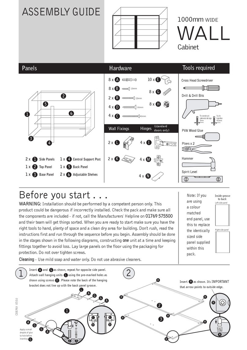
Norbord CSS 793 User manual
Norbord
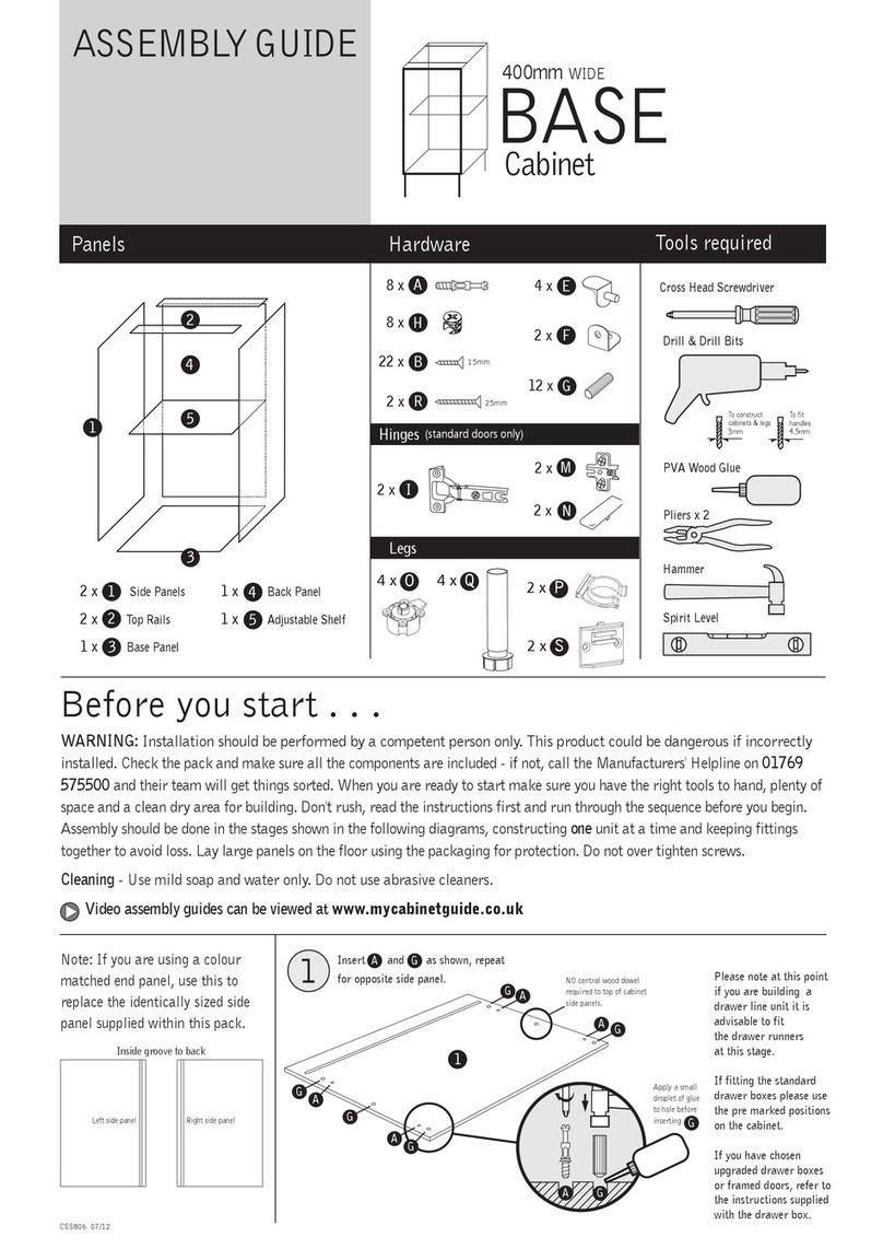
Norbord CSS806 User manual
Norbord
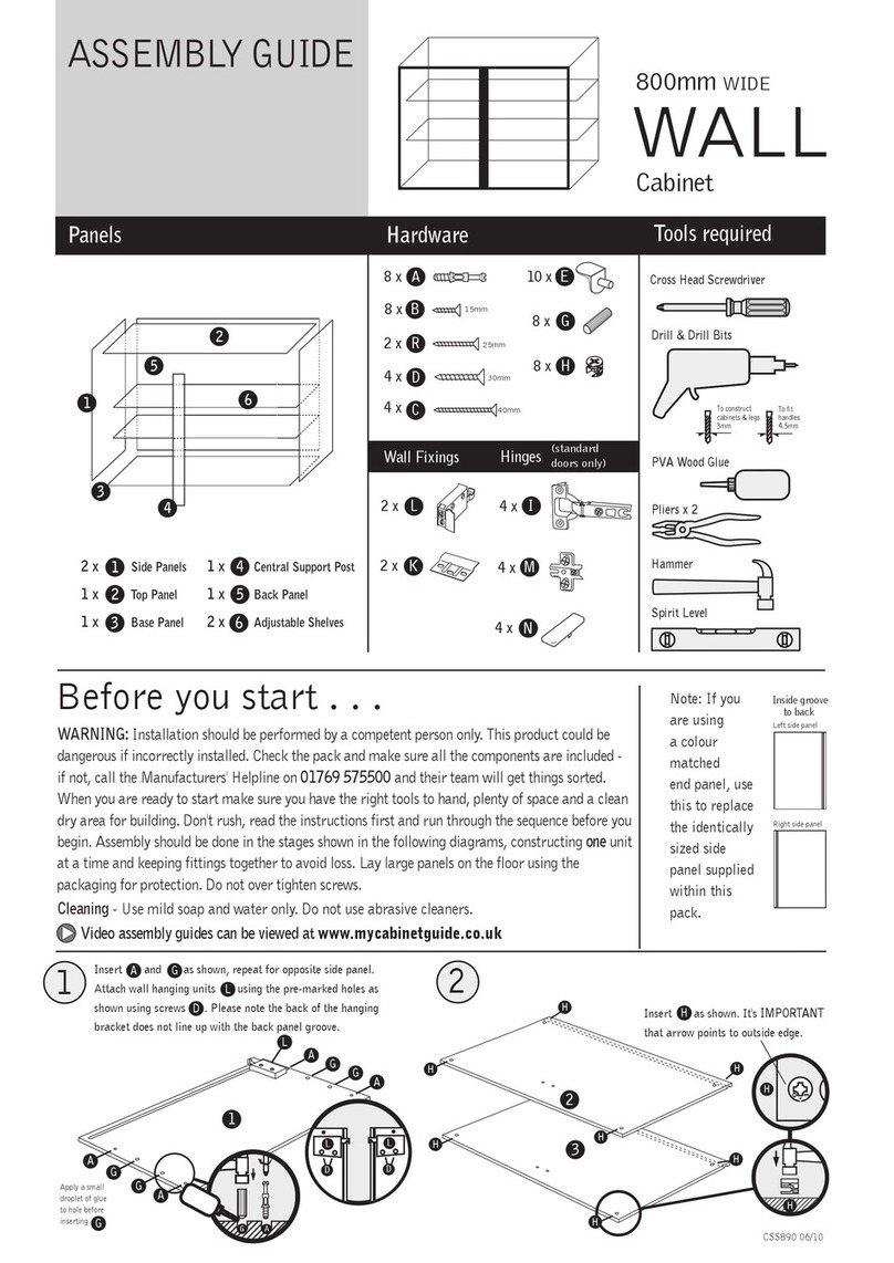
Norbord WALL CSS890 User manual
Popular Indoor Furnishing manuals by other brands
GPM
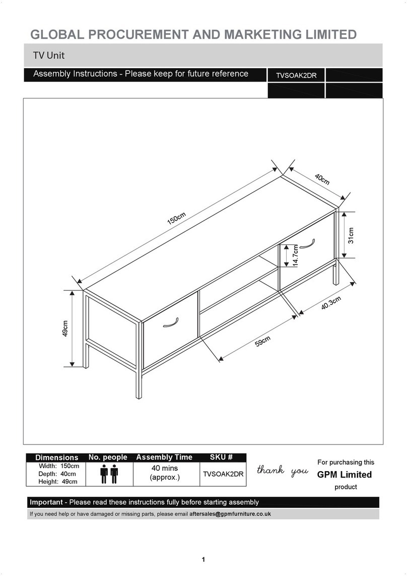
GPM TVSOAK2DR Assembly instructions
BRICK
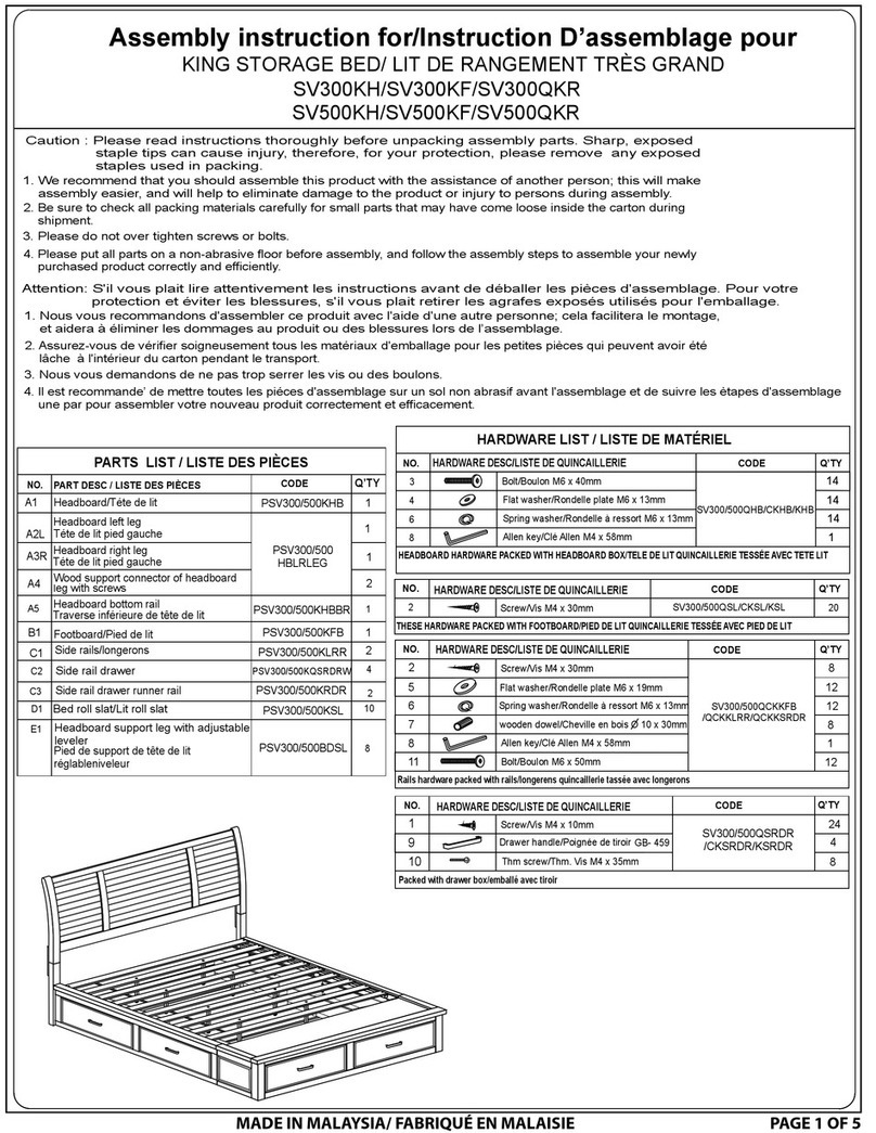
BRICK SV300KH Assembly instruction
Organized Living
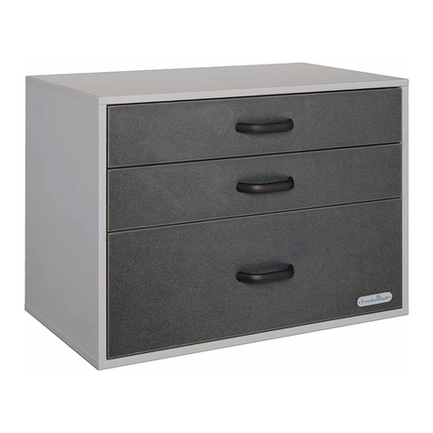
Organized Living freedomRail Garage 3 Drawer GOBox Assembly instructions
Bestar
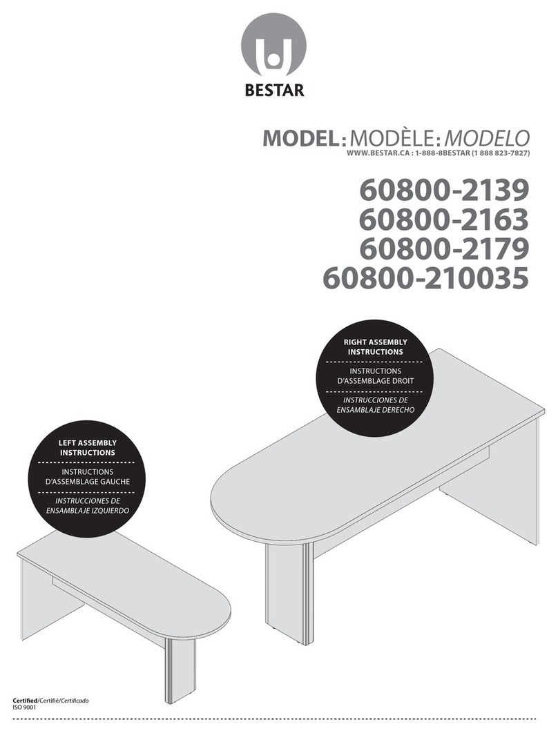
Bestar 60800-2139 Assembly instructions
The Stow Company
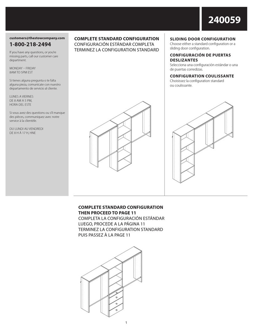
The Stow Company 240059 manual
Triarch
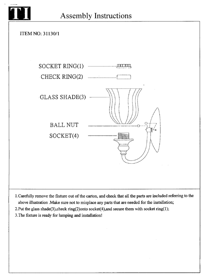
Triarch Indoor Lighting 31130/1 Assembly instructions
