manuals.online logo
Brands
  1. Home
  2. •
  3. Brands
  4. •
  5. Norbord
  6. •
  7. Indoor Furnishing
  8. •
  9. Norbord CSS791 User manual

Norbord CSS791 User manual

Position stay and secure with 2 x
and 2 x screws provided (standard
doors only). For framed doors, refer to
the instructions supplied in the
separate hinge pack.
R
Connect base panel
onto side panel as shown.
Repeat for top panel
Panels Hardware Tools required
15mm
25mm
8 x
6 x
4 x
8 x
D
30mm
4 x
A
8 x H
B
R
G
1 x P
600mm WIDE
Bridging Cabinet
WALL
Cross Head Screwdriver
H
H
H
H
H
H
H
H
HH
4
1
2
3
3
1
2
H
H
3
1
2
5
4
7
6
Insert as shown. It's IMPORTANT
that arrow points to outside edge.
Tighten clockwise
in 4 positions.
Connect side panel
as shown,
tighten clockwise
in 4 positions.
Slide back
panel into
groove.
Run small
bead of glue
along all
grooves
4
2
3
1
Now affix to wall
Joining and Levelling
of Cabinets
R
3mm
90
2
3
1
1
H
H
HH
H
R
B
B
Door
Cabinet
To fit door stay
Drill & Drill Bits
PVA Wood Glue
Pliers x 2
Hammer
Spirit Level
To construct
cabinets & legs
3mm
To fit
handles
4.5mm
Mark 20mm on a 3mm dia. drill bit with
masking tape. Drill between the 2 holes
drilled for the hinges, through one cabinet
side (16mm) and 4mm into the next,
stopping when you reach the marker.
Join the cabinets together with
2 x screws.
R
To fit door handles
4
CSS791 08/13
CSS791 08/13
3
G
A
GA
G
A
GA
L
G
Apply a small
droplet of glue
to hole before
inserting
1
A
G
DD
LL
AG
1
140mm
98mm
44mm
34mm
TOP OF CABINET
LH SIDE PANEL
2
108mm
32mm
Drill inside face of Bridging Cabinet Door with 2x Pilot Holes at positions shown.
34mm
2 x I
2 x N
2 x M
Marking the stay fixing positions on the
cabinet (standard doors only)
Insert and as shown, repeat for opposite side panel.
Attach wall hanging units using the pre-marked holes as
shown using screws . Please note the back of the hanging
bracket does not line up with the back panel groove.
H
D
L
Position your choice of handle
(available separately) using
the drilling guide available in
stores.
2 x L
2 x K
Fixing to Wall
Adjustment – IN & OUT to Wall
Adjustment – UP & DOWN to Wall
Spacing between side panels –
allow 18mm clearance each side
Measure
57mm from
top of unit
Position and secure fitting brackets to the wall with suitable fixings.
WARNING: This unit could be dangerous if fitted incorrectly to the
wall.(Fixings are not supplied with the pack as they vary according to the
type of walls you have. If you are unsure, ask an expert).
Hang cabinet onto
wall brackets
and adjust to level
as shown.
Ensure that front
face of unit is
vertical by using
spirit level.
K
K
K
K
K
K
K
K
Wall Fixings Hinges
(standard
doors only)
Drill 2x3mm pilot holes
for door stay screws to
inside face of Bridging
Cabinet Side Panel
If you have chosen framed doors, refer to the instructions
supplied in the separate hinge pack for stay fixing instructions.
Insert door hinge into
recess in door and affix
using 2x screws.
Turn screw as shown, to adjust the door position
B
N
Connect door hinge to cabinet
and tighten screw shown.
Affix hinge plate to cabinet using
pre-drilled holes with
pre-mounted screws.
After adjustment is complete
apply cover plate
IM
lenapfoegdE
Door hinges (standard doors only)
If you have chosen framed doors, refer to the instructions supplied in the
separate hinge pack for frame fixing, fitting and adjustment of hinges.
Before you start . . .
WARNING: Installation should be performed by a competent person only. This product could be dangerous if incorrectly installed. Check the pack and
make sure all the components are included - if not, call the Manufacturers' Helpline on 01769 575500 and their team will get things sorted. When you are
ready to start make sure you have the right tools to hand, plenty of space and a clean dry area for building. Don't rush, read the instructions first and run
through the sequence before you begin. Assembly should be done in the stages shown in the following diagrams, constructing one unit at a time and keeping
fittings together to avoid loss. Lay large panels on the floor using the packaging for protection. Do not over tighten screws.
Cleaning - Use mild soap and water only. Do not use abrasive cleaners.
Video assembly guides can be viewed at www.mycabinetguide.co.uk
Marking the stay fixing positions on the door (standard doors only)
NOTE: Some standard door ranges have different hinge fixing positions for the bridging
unit door, which may require you to drill some extra holes before assembling this unit.
Check your bridging unit door pack before assembling this unit. If any extra drilling is
required, you will find instructions in the door pack on how to do this.
This stay is designed for LH fixing only. However, if you wish to fit it to the RH side,
the 34mm dimension will need to be reduced to 14mm.
Drill 2 x 3mm
pilot holes
for door stay
screws
Position stay and secure with 2 x
and 2 x screws provided (standard
doors only). For framed doors, refer to
the instructions supplied in the
separate hinge pack.
R
Connect base panel
onto side panel as shown.
Repeat for top panel
Panels Hardware Tools required
15mm
25mm
8 x
6 x
4 x
8 x
D
30mm
4 x
A
8 x
H
B
R
G
1 x
P
600mm WIDE
Bridging Cabinet
WALL
Cross Head Screwdriver
H
H
H
H
H
H
H
H
HH
4
1
2
3
3
1
2
H
H
3
1
2
5
4
7
6
Insert as shown. It's IMPORTANT
that arrow points to outside edge.
Tighten clockwise
in 4 positions.
Connect side panel
as shown,
tighten clockwise
in 4 positions.
Slide back
panel into
groove.
Run small
bead of glue
along all
grooves
4
2
3
1
Now affix to wall
Joining and Levelling
of Cabinets
R
3mm
90
2
3
1
1
H
H
HH
H
R
B
B
Door
Cabinet
To fit door stay
Drill & Drill Bits
PVA Wood Glue
Pliers x 2
Hammer
Spirit Level
To construct
cabinets & legs
3mm
To fit
handles
4.5mm
Mark 20mm on a 3mm dia. drill bit with
masking tape. Drill between the 2 holes
drilled for the hinges, through one cabinet
side (16mm) and 4mm into the next,
stopping when you reach the marker.
Join the cabinets together with
2 x screws.
R
To fit door handles
4
CSS791 08/13
CSS791 08/13
3
G
A
GA
G
A
GA
L
G
Apply a small
droplet of glue
to hole before
inserting
1
A
G
DD
LL
AG
1
140mm
98mm
44mm
34mm
TOP OF CABINET
LH SIDE PANEL
2
108mm
32mm
Drill inside face of Bridging Cabinet Door with 2x Pilot Holes at positions shown.
34mm
2 x I
2 x
N
2 x M
Marking the stay fixing positions on the
cabinet (standard doors only)
Insert and as shown, repeat for opposite side panel.
Attach wall hanging units using the pre-marked holes as
shown using screws . Please note the back of the hanging
bracket does not line up with the back panel groove.
H
D
L
Position your choice of handle
(available separately) using
the drilling guide available in
stores.
2 x L
2 x
K
Fixing to Wall
Adjustment – IN & OUT to Wall
Adjustment – UP & DOWN to Wall
Spacing between side panels –
allow 18mm clearance each side
Measure
57mm from
top of unit
Position and secure fitting brackets to the wall with suitable fixings.
WARNING: This unit could be dangerous if fitted incorrectly to the
wall.(Fixings are not supplied with the pack as they vary according to the
type of walls you have. If you are unsure, ask an expert).
Hang cabinet onto
wall brackets
and adjust to level
as shown.
Ensure that front
face of unit is
vertical by using
spirit level.
K
K
K
K
K
K
K
K
Wall Fixings Hinges
(standard
doors only)
Drill 2x3mm pilot holes
for door stay screws to
inside face of Bridging
Cabinet Side Panel
If you have chosen framed doors, refer to the instructions
supplied in the separate hinge pack for stay fixing instructions.
Insert door hinge into
recess in door and affix
using 2x screws.
Turn screw as shown, to adjust the door position
B
N
Connect door hinge to cabinet
and tighten screw shown.
Affix hinge plate to cabinet using
pre-drilled holes with
pre-mounted screws.
After adjustment is complete
apply cover plate
IM
lenapfoegdE
Door hinges (standard doors only)
If you have chosen framed doors, refer to the instructions supplied in the
separate hinge pack for frame fixing, fitting and adjustment of hinges.
Before you start . . .
WARNING: Installation should be performed by a competent person only. This product could be dangerous if incorrectly installed. Check the pack and
make sure all the components are included - if not, call the Manufacturers' Helpline on 01769 575500 and their team will get things sorted. When you are
ready to start make sure you have the right tools to hand, plenty of space and a clean dry area for building. Don't rush, read the instructions first and run
through the sequence before you begin. Assembly should be done in the stages shown in the following diagrams, constructing one unit at a time and keeping
fittings together to avoid loss. Lay large panels on the floor using the packaging for protection. Do not over tighten screws.
Cleaning - Use mild soap and water only. Do not use abrasive cleaners.
Video assembly guides can be viewed at www.mycabinetguide.co.uk
Marking the stay fixing positions on the door (standard doors only)
NOTE: Some standard door ranges have different hinge fixing positions for the bridging
unit door, which may require you to drill some extra holes before assembling this unit.
Check your bridging unit door pack before assembling this unit. If any extra drilling is
required, you will find instructions in the door pack on how to do this.
This stay is designed for LH fixing only. However, if you wish to fit it to the RH side,
the 34mm dimension will need to be reduced to 14mm.
Drill 2 x 3mm
pilot holes
for door stay
screws

Other Norbord Indoor Furnishing manuals

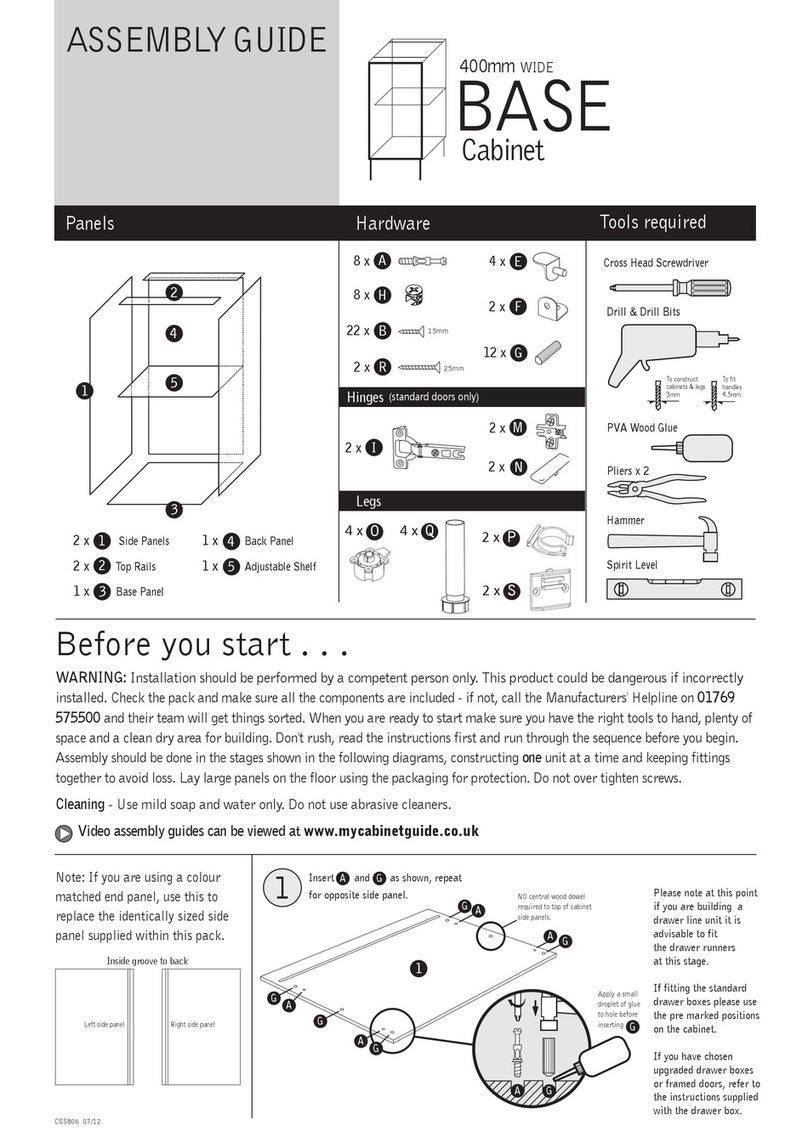
Norbord CSS806 User manual

Norbord

Norbord CSS806 User manual

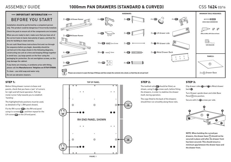
Norbord 1000mm PAN DRAWERS User manual

Norbord

Norbord 1000mm PAN DRAWERS User manual

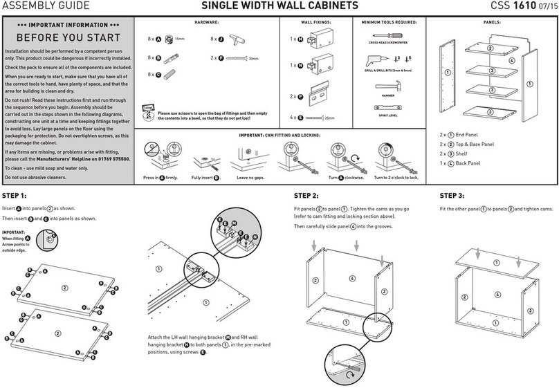
Norbord CSS 1610 User manual

Norbord

Norbord CSS 1610 User manual

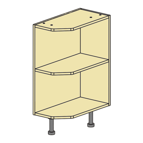
Norbord Shaped OPEN BASE Cabinets User manual

Norbord

Norbord Shaped OPEN BASE Cabinets User manual

Norbord CSS 805 User manual

Norbord

Norbord CSS 805 User manual

Norbord WALL CSS890 User manual

Norbord

Norbord WALL CSS890 User manual

Norbord CSS 793 User manual

Norbord

Norbord CSS 793 User manual

Norbord CSS 856 User manual

Norbord

Norbord CSS 856 User manual

Popular Indoor Furnishing manuals by other brands

HJH office TRON GI Assembly instructions

HJH office

HJH office TRON GI Assembly instructions

J.Burrows TYPHOON PRO JBRAPTBK Assembly instructions

J.Burrows

J.Burrows TYPHOON PRO JBRAPTBK Assembly instructions

Gelmar StarBox Slimline installation guide

Gelmar

Gelmar StarBox Slimline installation guide

Aqua ring Assembly instructions

Aqua

Aqua ring Assembly instructions

Studio Designs 13373 Assembly instructions

Studio Designs

Studio Designs 13373 Assembly instructions

Classic Exhibits euro lt HYBRIDS Mod-1122 manual

Classic Exhibits

Classic Exhibits euro lt HYBRIDS Mod-1122 manual

E-Ready Furniture THREE SHELF BOOKCASE LB-DUR-BS44 Assembly instructions

E-Ready Furniture

E-Ready Furniture THREE SHELF BOOKCASE LB-DUR-BS44 Assembly instructions

GFW LANCASTER Assembly instructions

GFW

GFW LANCASTER Assembly instructions

Leen Bakker VIC Assembly instruction

Leen Bakker

Leen Bakker VIC Assembly instruction

Multistore MAXI ULTRA-H1 Assembly instructions

Multistore

Multistore MAXI ULTRA-H1 Assembly instructions

Bestar 40166-1117 manual

Bestar

Bestar 40166-1117 manual

Allen + Roth WSCO-72C-AR manual

Allen + Roth

Allen + Roth WSCO-72C-AR manual

BIG FURNITURE WAREHOUSE Regal Ottoman Bedstead Assembly instructions

BIG FURNITURE WAREHOUSE

BIG FURNITURE WAREHOUSE Regal Ottoman Bedstead Assembly instructions

MAD terrazzo G56ST quick start guide

MAD

MAD terrazzo G56ST quick start guide

BDI CORRIDOR SV BAR 5621 instruction manual

BDI

BDI CORRIDOR SV BAR 5621 instruction manual

VIA Technologies Eclipse 646 Adjustment guide

VIA Technologies

VIA Technologies Eclipse 646 Adjustment guide

Malibu Boats 258/6890 Assembly instructions

Malibu Boats

Malibu Boats 258/6890 Assembly instructions

Lifely Nash Series Assembly instructions

Lifely

Lifely Nash Series Assembly instructions

manuals.online logo
manuals.online logoBrands
  • About & Mission
  • Contact us
  • Privacy Policy
  • Terms and Conditions

Copyright 2025 Manuals.Online. All Rights Reserved.