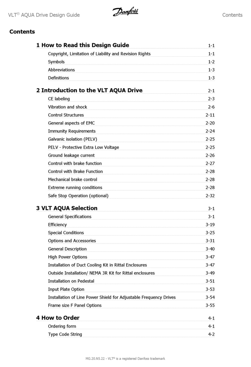
Table of Contents
BU 0240 en-US-3118 5
Pos: 10 /Al lg e mei n/S te u erm odul e/In hal ts ver z eic hnis @ 0\mod_1317978518480_14638.docx@ 14771@ @ 1
Table of Contents
=== En de der List e f ür T e xt mar ke I nh alt s ver z eic h nis == =
1General.........................................................................................................................................................9
1.1 Overview ............................................................................................................................................9
1.2 Delivery............................................................................................................................................10
1.3 Safety, installation and operating instructions ..................................................................................11
1.4 Warnings and hazard information ....................................................................................................16
1.4.1 Warnings and hazard information on the product...............................................................16
1.4.2 Warnings and hazard information in the document ............................................................17
1.5 Standards and approvals .................................................................................................................17
1.6 Model code/nomenclature................................................................................................................19
1.6.1 Nameplate ..........................................................................................................................19
1.6.2 Variable Frequency Drive model code - basic device.........................................................20
1.6.3 Variable Frequency Drive model code - connection unit ....................................................20
1.7 Output/size assignment....................................................................................................................21
1.8 Version with IP55/IP66 rating...........................................................................................................21
2Mounting and installation.........................................................................................................................23
2.1 Mounting SK 2xxE............................................................................................................................23
2.1.1 Installation of insulating plate – size 4 ................................................................................25
2.1.2 Motor installation steps.......................................................................................................26
2.1.2.1 Adapters for motor size 27
2.1.2.2 Dimensions, SK 2xxE mounted on motor 28
2.2 Braking resistor (BW) - (from size 1)................................................................................................29
2.2.1 Internal braking resistor SK BRI4-…...................................................................................29
2.2.2 External braking resistor SK BRE4-... / SK BRW4-… / SK BREW4-…...............................32
2.3 Electrical connection ........................................................................................................................33
2.3.1 Wiring guidelines ................................................................................................................34
2.3.2 Electrical connection of power unit .....................................................................................35
2.3.3 Electrical connection of the control unit ..............................................................................36
2.4 Operation in potentially explosive environments..............................................................................41
2.4.1 Operation in potentially explosive environments - ATEX zone 22 3D.................................42
2.4.1.1 Modification of the device for compliance with category 3D 42
2.4.1.2 Options for ATEX zone 22, category 3D 43
2.4.1.3 Maximum output voltage and torque reduction 45
2.4.1.4 Commissioning information 45
2.4.1.5 EU conformity declaration - ATEX 47
2.4.2 Operation in potentially explosive environments - EAC Ex.................................................48
2.4.2.1 Modification of the device 48
2.4.2.2 Further information 49
2.4.2.3 EAC Ex Certificate 49
3Display, operation and options ................................................................................................................50
3.1 Control and parameterization options ..............................................................................................51
3.1.1 Use of control and parameterization units ..........................................................................52
3.1.2 Potentiometer adapter, SK CU4-POT.................................................................................53
4Commissioning .........................................................................................................................................55
4.1 Factory settings................................................................................................................................55
4.2 Starting up the device ......................................................................................................................57
4.2.1 Connection .........................................................................................................................57
4.2.2 Configuration ......................................................................................................................58
4.2.2.1 Parameterization 58
4.2.2.2 DIP switches (S1) 59
4.2.2.3 DIP switches, analog input (only SK 2x0E) 61
4.2.2.4 Potentiometers P1 and P2 (SK 2x0E size 4 and SK 2x5E) 62
4.2.3 Commissioning examples...................................................................................................63
4.2.3.1 SK 2x0E minimum configuration 63
4.2.3.2 SK 2x5E minimum configuration 64
5Parameter...................................................................................................................................................66
5.1 Parameter overview .........................................................................................................................69
6Operating status messages .....................................................................................................................74


