www.nordsonefd.com
[email protected] 800-556-3484 Sales and service of Nordson EFD dispensing systems are available worldwide.781Mini Series Spray Valve
8
Making the System Connections
For complete installation, setup, and testing instructions, refer to the controller operating manual.
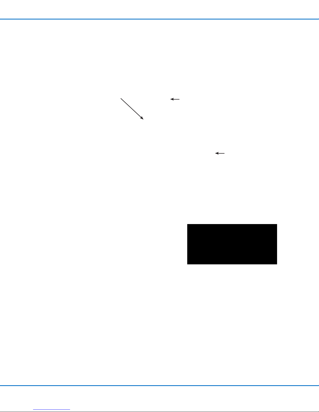
ValveMate 8040 System with a 781Mini Valve
NOTE: The area of spray coverage is determined (1) by the distance between the spray valve nozzle and the work surface and
(2) by the stroke adjustment and uid pressure. Refer to “Round Pattern Spray Area Coverage” on page 10 to determine the
distance.
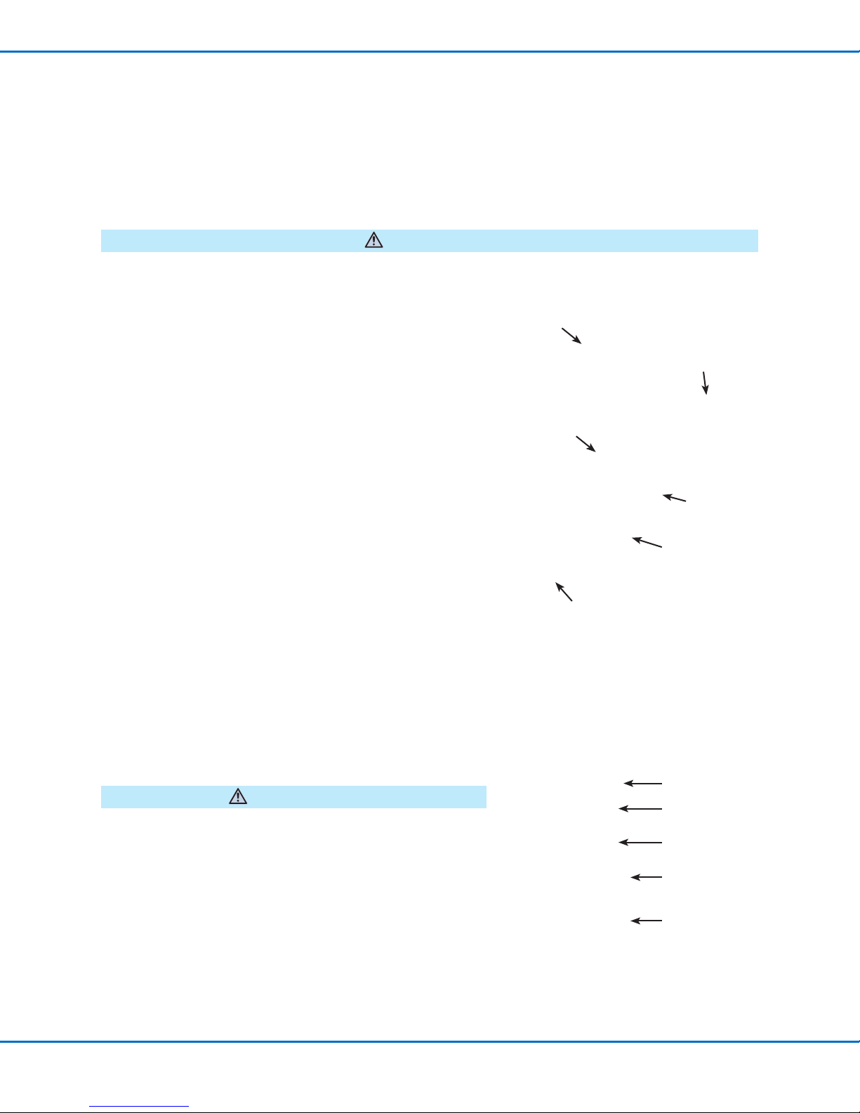
Always de-pressurize the uid reservoir before opening it. To do this, slide the shutoff valve on the air line away from the reservoir.
Before opening the reservoir, check the pressure gauge to verify that pressure is zero (0). If using an EFD tank, also open the
pressure relief valve.
On all EFD cartridge reservoirs, the unique threaded design provides fail-safe air pressure release during cap removal.
CAUTION
1. Connect the valve actuating air tubing
(white) and the nozzle air tubing
(black) to the ValveMate 8040 dual
solenoid pack used to control valve
open time (white) and nozzle air
(black).
2. Connect the white male quick-
connect on the constant air line to the
white female quick-connect on the
5-micron lter / regulator.
3. Install the syringe barrel reservoir
on the uid inlet tting (for use with
Optimum® syringe barrels). For low
viscosity uids, ll the reservoir after
installing it on the uid inlet tting.
NOTE: Fill syringe barrel reservoirs no
more than 2/3full.
4. Attach the syringe barrel adapter
to the barrel reservoir using the air
interconnect coupler to connect the
adapter to the uid pressure regulator
air line.
5. Set the uid pressure regulator to
low for thin uids and higher for thick
uids.
6. Use the MODE button on the
ValveMate controller to place the
controller in the PURGE mode. In the
PURGE mode only, channels 1 and
3 can be selected independently
without nozzle air pressure.
7. Use the stroke control knob on the
781Mini valve to set the desired ow
rate. Lower strokes (< 5) will produce
smaller patterns. Check the ow rate
by actuating the controller in the TIME
OVERRIDE mode.
NOTE: Make valve stroke
adjustments only when the valve is
not cycling.
8. Set the nozzle air pressure to 0.7 bar
(10 psi) and actuate the controller.
The valve will produce a ne spray.
To change uid ow, use the stroke
control knob and / or the reservoir
pressure. To change the nozzle air,
use the nozzle air pressure regulator.
Higher pressures will provide ner
spray.
NOTE: The 5-micron lter / regulator
assembly is not included. Order
separately:
7020584: 0–100 psi lter / regulator
7020585: 0–15 psi lter / regulator
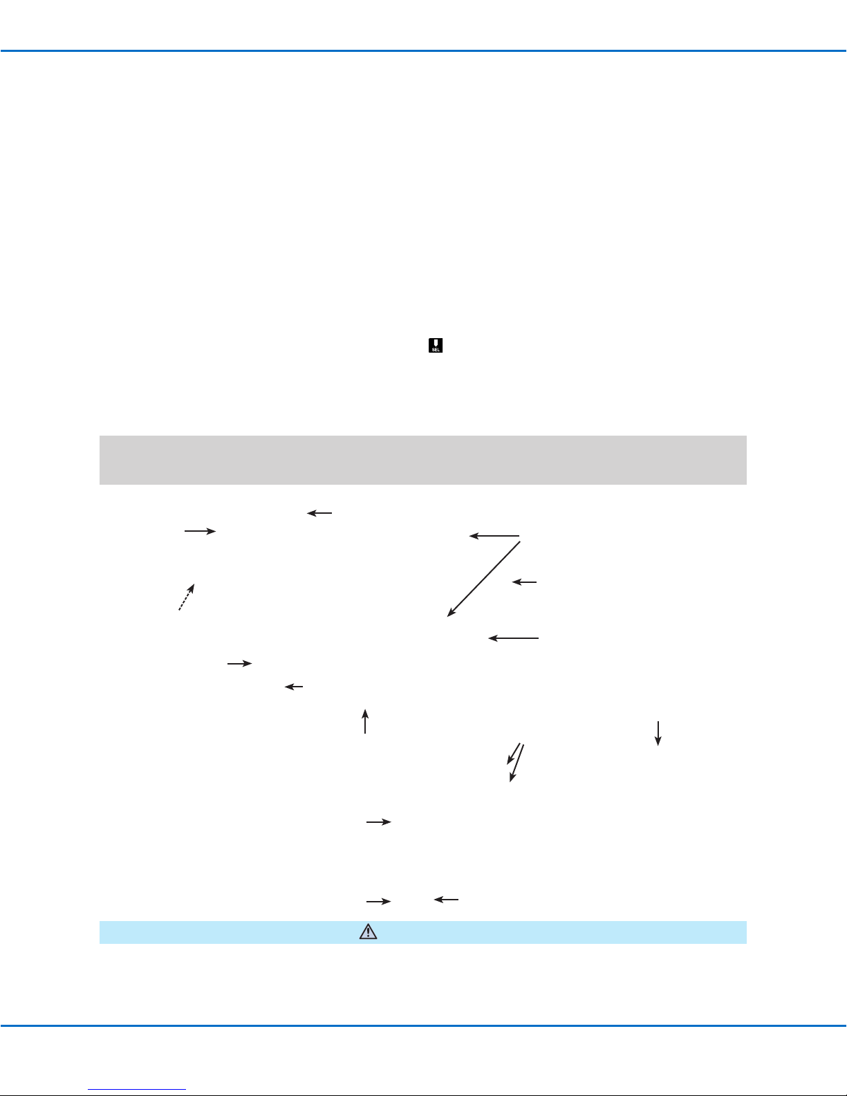
Nozzle air pressure
regulator
5-micron lter /
regulator
781Mini valve
30 cc syringe barrel
Constant air
Fluid pressure
regulator
Constant uid
pressure
Valve actuating air (white)
ValveMate 8040
Controller
Plant air
4.8–6.8 bar
(70–90 psi)
Dual solenoid pack
Nozzle air (black)
Solenoid cables
Fluid inlet tting