manuals.online logo
Brands
  1. Home
  2. •
  3. Brands
  4. •
  5. Nordson EFD
  6. •
  7. Control Unit
  8. •
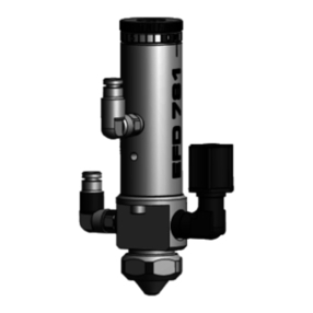
  9. Nordson EFD 725HF-SS Manual

Nordson EFD 725HF-SS Manual

™
Electronic pdf les of Nordson EFD
manuals are also available at
nordsonefd.com
IMPORTANT!
Save this Sheet.
Forward to
Maintenance or
Tool Crib Supervisors
725HF-SS and 725HF-A Piston Valves
Maintenance & Parts Guide
725HF-SS and 725HF-A Piston Valves
2nordsonefd.com [email protected] 800-556-3484 Sales and service of Nordson EFD dispensing systems are available worldwide.
Valve Disassembly and
Reassembly Procedures
To prevent damage, the valve must be disassembled
starting at the uid outlet end of the valve.
CAUTION
1. Put threaded rod in mounting hole.
2. Remove body cap.
3. Remove sealing head. 
4. With a wrench on the ats of the air cylinder body,
turn to loosen uid body.
5. Remove uid body. 
6. Remove input air hose from push-in tting on air
cap.
7. Insert 1/8" hex wrench through air inlet hole in cap
and turn shaft, locking screw out two turns. 
8. Using the hex on the shaft, unthread shaft, and
remove shaft and diaphragm. 
9. Unscrew air cylinder cap from air cylinder
body. 
10. Remove piston and spring.
NOTE: Before reassembling valve, clean all parts,
replace O-rings, sealing head and diaphragm.
Inspect for damaged threads, piston pins for
straightness and uid body seat for pitting.
Do not thread uid inlet ttings too far into the valve.
Doing so can obstruct the piston shaft, causing
leakage, poor dispensing performance, and damage
to the valve.
CAUTION
Reassemble the valve in reverse order of disassembly.
Lubricate parts indicated with Nye Lubricant #865
included in the General Maintenance Kit.
O-ring only
Fluid body
#7021023
(stainless steel)
#7021040
(acetal copolymer)
Fluid tting
#7021038
Body cap
with O-ring
#7021025
(stainless steel)
#7021042
(acetal copolymer)
Sealing head
#7021026 (stainless steel)
#7021045 (PTFE-coated
stainless steel)
Shoulder “A”
Shaft
#7021029 (stainless steel)
#7021043 (PTFE-coated
stainless steel)
Diaphragm
#7020925
1
2
3
5
8
725HF-SS and 725HF-A Piston Valves
3nordsonefd.com [email protected] 800-556-3484 Sales and service of Nordson EFD dispensing systems are available worldwide.
Parts that require a specic torque when reassembling the valve.
General Maintenance Kit
#7021019 for 725HF-SS (7021020) valve
#7021016 for 725HF-A (7021015) valve†
Includes air cylinder and body cap O-rings,
diaphragm, sealing head with screw and lubricant.
†Repair kit for 725HF-A valve also includes
PTFE-coated sealing-head screws.
Maintenance Tools:
1/8" hex wrench
1/4" at-tip screwdriver
3/8" box wrench
7/8" open-end wrench
8" adjustable wrench
1/4" NPT male pipe or rod
Air cylinder
body assembly
#7020924
Push-in tting
1/8 NPT x 4 mm
(5/32")
#7021718
Nye gel lubricant, 1 gram
foil packet (not shown)
Air piston with O-ring
and shaft locking screw
#7020917
O-ring only #7014738
Shaft
locking
screw
#7014737
Air cylinder cap
with O-ring
#7020910
O-ring only
#7014735
4
6
7
9
10
725HF-SS assembly of piston,
diaphragm and shaft.
step part newton meters (inch pounds)
3 Sealing head screw 1.69 Nm (15 inch pounds)
5 Stainless steel uid body 10.8 - 13.6 Nm (8 - 10 foot pounds)
5 Acetal uid body .033 Nm (.30 inch pounds)
7 Shaft locking screw 2.82 Nm (25 inch pounds)
8 Shaft 1.69 Nm (15 inch pounds)
9 Air cylinder cap 10.8 Nm (8 foot pounds)
Thrust washer
#7014739
Spring
#7014734
For Nordson EFD sales and service in over
40 countries, contact Nordson EFD or go to
nordsonefd.com
Global
East Providence, RI USA
800-556-3484; +1-401-431-7000
[email protected]
Europe
Dunstable, Bedfordshire, UK
0800 585733; +44 (0) 1582 666334
[email protected]
Asia
China: +86 (21) 3866 9006; [email protected]
India: +91 80 4021 3600; [email protected]
Japan: +81 03 5762 2760; [email protected]
Korea: +82-31-736-8321; [email protected]
SEAsia: +65 6796 9522; [email protected]
©2016 Nordson Corporation 7026828 v012416
725HF-SS and 725HF-A Piston Valves
Troubleshooting Guide
No uid ow
• If valve operating air pressure is too low, the valve
will not open. Increase air pressure to 4.8 bar
(70psi) minimum.
• The reservoir air pressure may not be high
enough. Increase pressure.
• The dispensing nozzle may be clogged. Replace
nozzle.
• Fluid may have solidied in the uid body. Clean
the uid body.
Fluid drools after the valve closes,
eventually stopping
• This is caused when air is trapped in the
outlet section of the uid body or the uid has
entrapped air. The air will expand after the valve
closes, causing extrusion until the air reaches
atmospheric pressure.
• Purge the valve by dispensing at a steady
ow until clear. If a small tip is used, it may
be necessary to remove the tip while purging
to obtain sufcient ow to carry the air down
through the tip adapter.
• If the uid has entrapped air, the material must be
degassed before dispensing.
NOTE: For stripes and lines, input air pressure
can be lowered to eliminate opening surge.
Fluid drips at a steady rate after
the valve closes
• A steady drip indicates failure of the sealing
head to close fully due to particle build-up or
wear. In either case, replace the sealing head in
accordance with the maintenance instructions.
• Fluid leakage can also occur when a uid inlet
tting is threaded too far into the valve, thus
obstructing the piston shaft. Ensure that the uid
inlet tting is properly installed.
Valve responds slowly when opening and
closing
• Valve response is related to control air hose
length and size. The valve is supplied with 5-feet
of 4 mm (5/32") tubing attached. Any additional
length or size change will affect response time.
Check to be sure the length and size have not
been changed.
Fluid ows out of the drain hole
• Fluid owing out of the drain hole indicates a
ruptured diaphragm. Replace in accordance with
the maintenance instructions.
Inconsistent deposits
• Inconsistent deposits can result if the air pressure
controlling the valve and/or supplying the
reservoir is uctuating or if the valve operating
pressure is less than 4.8 bar (70 psi). Check to
be sure air pressures are constant and the valve
operating pressure is 4.8 bar (70 psi).
• The time the valve is open must be constant.
Check to be sure the valve controller is providing
a consistent output.

This manual suits for next models

1

Other Nordson EFD Control Unit manuals
Nordson EFD 725HF User manual

Nordson EFD

Nordson EFD 725HF User manual

Nordson EFD 741V Series User manual

Nordson EFD

Nordson EFD 741V Series User manual
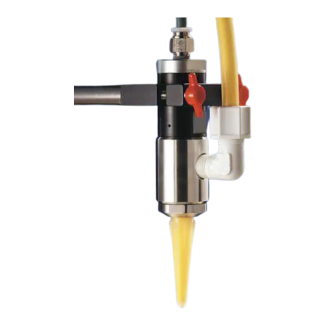
Nordson EFD 725HF-SS Manual

Nordson EFD

Nordson EFD 725HF-SS Manual

Nordson EFD 7860C-RS User manual

Nordson EFD

Nordson EFD 7860C-RS User manual

Nordson EFD 752V-HL User manual

Nordson EFD

Nordson EFD 752V-HL User manual

Nordson EFD 741MD-SS Series User manual

Nordson EFD

Nordson EFD 741MD-SS Series User manual

Nordson EFD 750 Series User manual

Nordson EFD

Nordson EFD 750 Series User manual
Nordson EFD 725DA-SS Manual

Nordson EFD

Nordson EFD 725DA-SS Manual
Nordson EFD 736HPA-NV Manual

Nordson EFD

Nordson EFD 736HPA-NV Manual
Nordson EFD 781Mini Series User manual
Nordson EFD

Nordson EFD 781Mini Series User manual

Nordson EFD 745NC User manual

Nordson EFD

Nordson EFD 745NC User manual

Nordson EFD 782RA Manual

Nordson EFD

Nordson EFD 782RA Manual
Nordson EFD 754V-SS Manual

Nordson EFD

Nordson EFD 754V-SS Manual
Nordson EFD 752V Series Manual

Nordson EFD

Nordson EFD 752V Series Manual

Nordson EFD 754V-SS User manual

Nordson EFD

Nordson EFD 754V-SS User manual
Nordson EFD Liquidyn P-Jet SolderPlus User manual

Nordson EFD

Nordson EFD Liquidyn P-Jet SolderPlus User manual

Nordson EFD 741MD-SS Series Manual

Nordson EFD

Nordson EFD 741MD-SS Series Manual

Nordson EFD 750V Manual

Nordson EFD

Nordson EFD 750V Manual

Nordson EFD 736HPA Manual

Nordson EFD

Nordson EFD 736HPA Manual
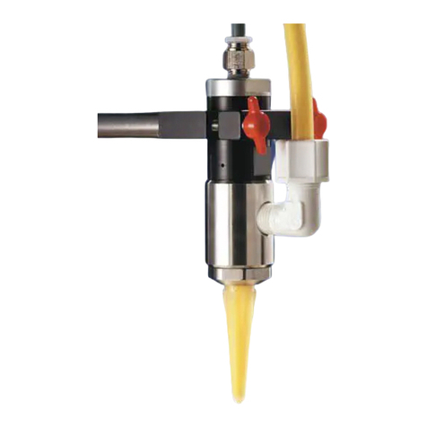
Nordson EFD 725HF Series User manual

Nordson EFD

Nordson EFD 725HF Series User manual

Nordson EFD 781S Series User manual

Nordson EFD

Nordson EFD 781S Series User manual

Popular Control Unit manuals by other brands
iNetVu STM Satlink 2900 user guide

iNetVu

iNetVu STM Satlink 2900 user guide

scigiene RFR-0510-2 user guide

scigiene

scigiene RFR-0510-2 user guide

ABB REF 542plus Operator's manual

ABB

ABB REF 542plus Operator's manual

Waters 61164 installation guide

Waters

Waters 61164 installation guide

Arsin AR1230 user manual

Arsin

Arsin AR1230 user manual

Baker Hughes Masoneilan 41005 Series instruction manual

Baker Hughes

Baker Hughes Masoneilan 41005 Series instruction manual

Cabletron Systems SmartSwitch 9500 Hardware and installation guide

Cabletron Systems

Cabletron Systems SmartSwitch 9500 Hardware and installation guide

SEW-Eurodrive Movidrive MDX61B manual
SEW-Eurodrive

SEW-Eurodrive Movidrive MDX61B manual

McQuay OM 1057 Operation manual

McQuay

McQuay OM 1057 Operation manual
Cosmo CFWME Installation and operating manual
Cosmo

Cosmo CFWME Installation and operating manual

FrSky XJT Lite D8 instruction manual

FrSky

FrSky XJT Lite D8 instruction manual
Pneumax 2 SAFELI 412/2 Series Installation, Use and Maintenance Instruction

Pneumax

Pneumax 2 SAFELI 412/2 Series Installation, Use and Maintenance Instruction

ICP DAS USA ET-2200 Series quick start

ICP DAS USA

ICP DAS USA ET-2200 Series quick start

Siemens MPS-6 installation instructions

Siemens

Siemens MPS-6 installation instructions

ARI Stevi 422 Series Operating and installation instructions

ARI

ARI Stevi 422 Series Operating and installation instructions

RAK RAK815 user manual

RAK

RAK RAK815 user manual

Chandler Systems DROP CS125 Series manual

Chandler Systems

Chandler Systems DROP CS125 Series manual

Fulling Motor FD542 user manual

Fulling Motor

Fulling Motor FD542 user manual

manuals.online logo
manuals.online logoBrands
  • About & Mission
  • Contact us
  • Privacy Policy
  • Terms and Conditions

Copyright 2025 Manuals.Online. All Rights Reserved.