41-VL500-OC-01
Issued 8/01 7
Vista Control System Programming Procedures (contd)
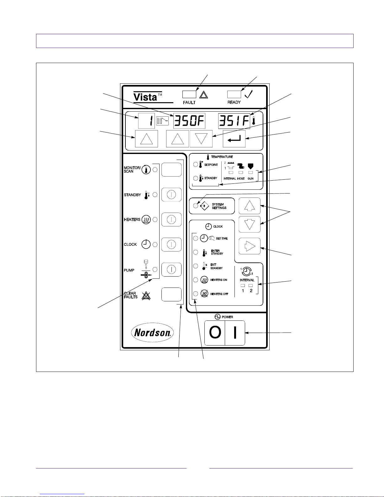
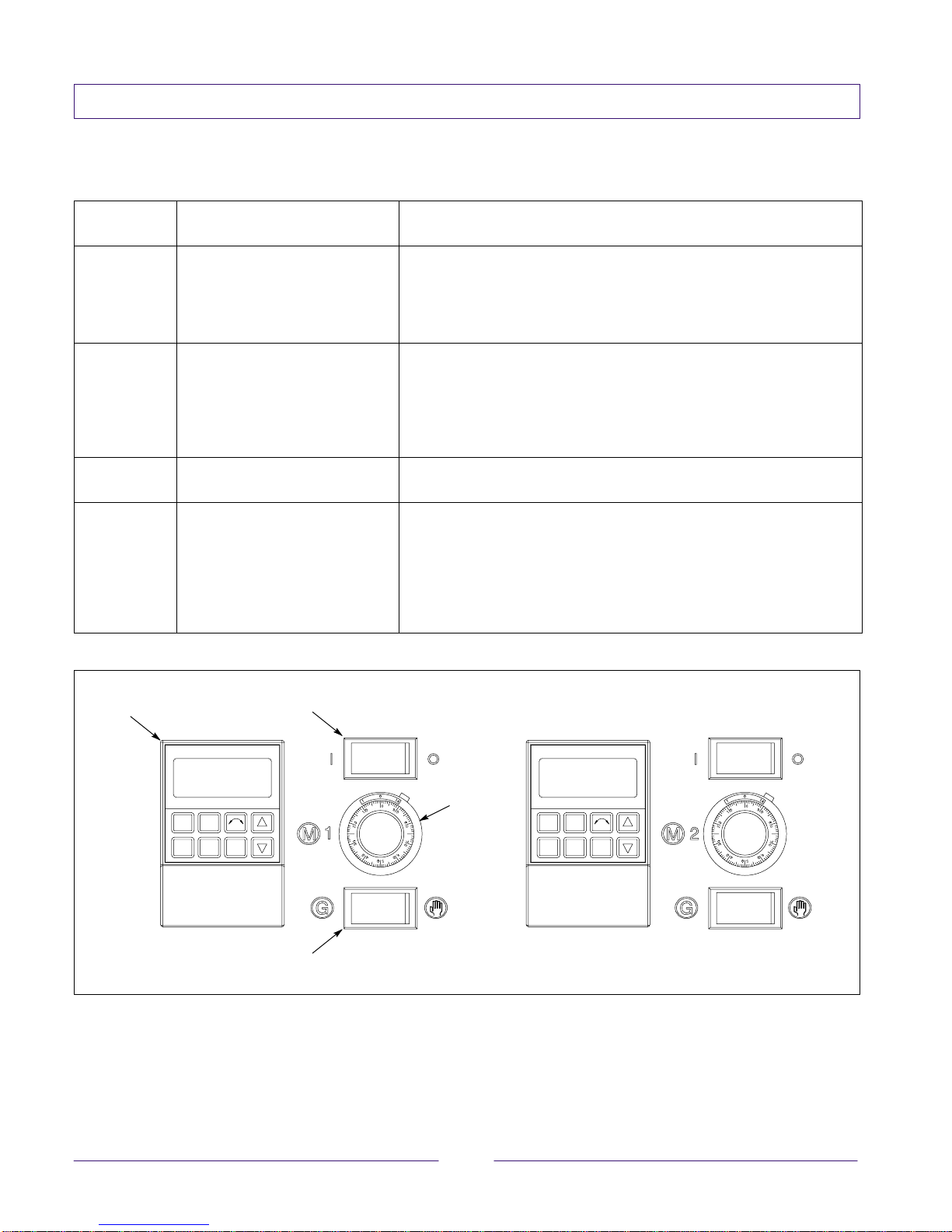
NOTE: See Figure 4 for the location of the displays,
keys, and lights on the Vista control panel.
Setting the Clock
1. Press the up or down arrow keys next to the
SYSTEMS SETTINGS light until the SET TIME
light turns on.
2. Press the up arrow key under the selector display
until the correct day code is shown (1=Monday,
2=Tuesday, and so on); then press enter.
3. Press the up or down arrow key under the
multipurpose display until the correct hour is
shown in the left side of the display; then press
enter.
4. Press the up or down arrow key under the
multipurpose display until the correct minutes are
shown on the right side of the display; then press
enter.
5. Press the MONITOR/SCAN key to exit the
clock-setting mode.
Setting Heaters On/Off or Enter/Exit
Standby Times
1. Press the up or down arrow keys next to the
SYSTEM SETTINGS light until the HEATERS ON,
HEATERS OFF, ENTER STANDBY, or EXIT
STANDBY light turns on.
2. Press the right arrow key (under the up/down
arrow keys) until the INTERVAL 1 or INTERVAL 2
light turns on. You can program two sets of times
for each feature (heaters on/off or enter/exit
standby).
3. Press the up arrow key under the selector display
until the correct day code is shown (1=Monday,
2=Tuesday, and so on); then press enter.
4. Press the up or down arrow key under the
multipurpose display until the correct hour is
shown in the left side of the display; then press
enter. If you wish to delete a time, press the key
until four dashes appear in the display; then press
enter and skip to step 7.
5. Press the up or down arrow key under the
multipurpose display until the correct minutes are
shown on the right side of the display; then press
enter.
6. Repeat steps 1–5 for each interval time you wish
to program.
7. Press the MONITOR/SCAN key to exit the heaters
on/off or enter/exit standby setting mode.
Using the Automatic Functions
If you want the automatic, clock-related functions to
occur (heaters on/off and enter/exit standby), press
the CLOCK key to turn the clock on. The CLOCK light
turns on when the clock is on.
Checking the Warning or Fault Log
1. Press the up or down arrow keys next to the
SYSTEMS SETTINGS light until the light turns on.
2. Press the up arrow key under the selector display
until feature number 35, 36, 37, (first, second, and
third most recent warnings) or 26, 27, or 28 (first,
second, and third most recent faults) appears.
3. The multipurpose display will show two numbers:
one that represents the affected zone and one that
represents the type of warning or fault that
occurred. Refer to Table 2.
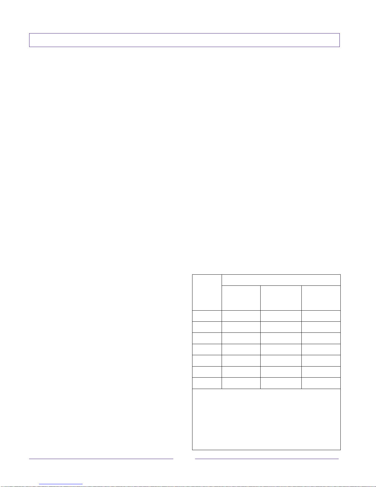
Table 2 Warning/Fault Log Numbers (See Note)
Warning
Number Fault
Number Meaning
not used 0No fault
not used 1Zone below operating
temperature setpoint
2 2 Open RTD
3 3 Shorted RTD
4 4 Zone out of band or
undertemperature
not used 5Defective control board
not used 6Brownout occurred
NOTE: The first number in the multipurpose display
represents the affected zone: 0 = reservoir, 1 = grid,
2–7 = hoses 1–6, and 8–13 = applicators 1–6.
Remember that if you have heated-air zones, that zone
number will be represented as one of the hose or
applicator zone numbers. The second number in the
multipurpose display represents the warning or fault
number.