Nordson FP-200 User manual

Instruction Sheet
Part 237494_02
E2012 Nordson Corporation
P/N 237494_02
Converting an FP-200 Extrusion Gun to
an FP-200 Swirl Gun
WARNING! Allow only qualified personnel to perform the following tas s.
Follow the safety instructions in this document and all other related
documentation.
Introduction
This conversion it provides instructions to convert an FP-200 extrusion gun
(P/N 234897) to an FP-200 swirl gun (P/N 234896). It does not
accommodate any other FP-200 gun part numbers.
The Nordson FP-200 gun, when combined with the appropriate
balance-assist devices, allows the operator to maintain a neutral wrist
position while manually applying hot melt adhesives and sealants to
horizontal substrates. Two versions of the FP-200 gun are available:
extrusion and swirl. Extrusion guns can meet a wide variety of bead
deposition requirements while swirl guns permit exceptional control of spiral
pattern density and size.
Nordson offers two conversion its: One to convert an extrusion gun to
a swirl gun and one to convert a swirl gun to an extrusion gun. This
instruction sheet contains the procedures for converting an extrusion gun to a
swirl gun.
Using this Instruction Sheet
This instruction sheet contains the following procedures:
S
Preparing to Convert an FP-200 Gun. Complete this procedure
before performing the conversion.
S
Converting an FP-200 Extrusion Gun to a Swirl Gun
S
Restoring the System to Normal Operation
Use the parts lists at the end of this instruction sheet to order any necessary
Nordson parts, such as swirl nozzles or the FP-200 swirl gun heat shield.

Converting an FP-200 Extrusion Gun to an FP-200 Swirl Gun
2
Part 237494_02
E2012 Nordson Corporation
Preparing to Convert an FP-200 Gun
WARNING! Hot! Ris of burns! Hot applicator parts, splashed hot melt
material, and hot gun surfaces can cause severe burns. Wear long-sleeved,
heat-protective clothing, safety goggles, and heat-protective gloves. Hot
melt material may be released forcefully.
WARNING: Ris of burns. System or material pressurized. Air trapped in
hoses and guns can spit out molten adhesive that can cause severe burns.
Failure to relieve hydraulic pressure can result in serious burns. Relieve
hydraulic pressure when instructed to do so.
WARNING! Even when switched off, Nordson applicators, hoses, and guns
contain electrical potentials that can cause death. Disconnect and loc out
line voltage to the applicator when instructed to do so.
1. Relieve hydraulic pressure (refer to the Relieving ydraulic Pressure
procedure in the FP-200 gun product manual).
2. Switch the applicator circuit brea er to the OFF position.
3. Disconnect and loc out electrical power to the applicator.
4. Shut off the air supply to the gun.
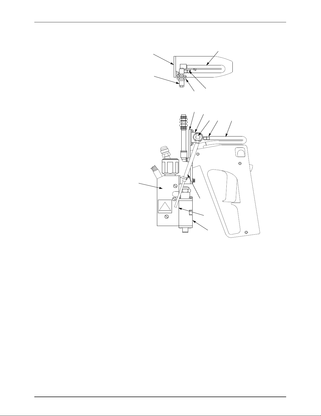
5. Remove the heat shield from the existing gun as follows:
a. Remove the auxiliary guide handle.
b. Disconnect the extrusion air line from the service bloc .
c. Remove the heat shield.
d. Reconnect the extrusion air line. Do not reinstall the auxiliary guide
handle.
6. Remove the existing gun from the suspension system by disconnecting
the hose hydraulically and electrically and by disconnecting the air line.

Converting an FP-200 Extrusion Gun to an FP-200 Swirl Gun
3
Part 237494_02
E2012 Nordson Corporation
Converting an FP-200 Extrusion Gun to a Swir Gun
CAUTION! The it for converting an extrusion gun to a swirl gun does not
include a heat shield. To comply with Underwriter's Laboratory (UL),
Canadian (C-UL), and Conformité Européenne (CE) standards, heat shield
P/N 234 965 must be used on the converted swirl gun. The extrusion gun
heat shield is 19 mm (
3
/
4
in.) shorter than the swirl gun heat shield and thus
cannot sufficiently cover a swirl gun as required to meet UL, C-UL, and CE
safety requirements.
Follow this procedure to convert an FP-200 extrusion gun to a swirl gun.
Figures 1 and 2 identify the components referred to in the procedure
(for clarity, the heat shield is not shown).
See Figure 1.

Converting an FP-200 Extrusion Gun to an FP-200 Swirl Gun
4
Part 237494_02
E2012 Nordson Corporation
Converting an FP-200 Extrusion Gun to a Swir Gun
(contd)
1
10
5
1
34
9
8
6
2
5
3
4
7
Figure 1 FP-200 Extrusion Gun Components
1. Gun mounting plate
2. Mounting brac et
3. Extrusion air line universal elbow
4. Outlet air line swivel fitting
5. Outlet air line
6. Extrusion air line
7. Extrusion air line male connector
and tube nut
8. Module
9. Service bloc
10. Bul head fitting

Converting an FP-200 Extrusion Gun to an FP-200 Swirl Gun
5
Part 237494_02
E2012 Nordson Corporation
Figure 1FP-200 Swirl Gun Components
1. Multi-plane swivel fitting
(hydraulic hose connection)
2. High-temperature air line tube
3. Gun mounting plate
4. Air regulator
5. Urethane air line tube
6. Trigger safety
7. Trigger
8. Trigger handle
9. Extrusion air line
10. Module (CF-200 Wide Pattern)
11. Air manifold
12. Swirl air line
13. Service bloc (gun body)
14. Cordset connection
15. Mounting brac et

Converting an FP-200 Extrusion Gun to an FP-200 Swirl Gun
6
Part 237494_02
E2012 Nordson Corporation
Disassembling the Extrusion Gun
Ma e sure you have completed the Preparing to Convert an FP-200 Gun
procedure before proceeding.
See Figure 3 for the following procedure.
1. Unthread and remove the outlet air line swivel fitting from the outlet air
line universal elbow.
2. Disconnect the mounting brac et from the gun mounting plate.
3. Disconnect the outlet air line universal elbow from the bul head fitting
and set it aside. It will be used later.
4. Disconnect the bul head fitting and mounting brac et from the extrusion
air line universal elbow.
5. Extract the bul head fitting from the mounting brac et.
5
4
2
3
1
6
Figure 2 Disconnecting the Extrusion Air Line (Top View)
1. Gun mounting plate
2. Outlet air line universal elbow
3. Outlet air line swivel fitting
4. Bul head fitting (including washers
and loc ing nut)
5. Extrusion air line universal elbow
6. Mounting brac et

Converting an FP-200 Extrusion Gun to an FP-200 Swirl Gun
7
Part 237494_02
E2012 Nordson Corporation
Assembling the Extrusion Gun
See Figure 4 for steps 1 through 5.
1. Reinstall the mounting brac et on the opposite side of the gun mounting
plate. Ensure that the mounting brac et is positioned as shown in
Figure 4.
2. Install the air regulator in the mounting brac et by removing one loc ing
nut and washer, inserting the regulator through the hole in the mounting
brac et, then replacing and tightening the loc ing nut and washer.
Ensure that the T manifold inlet is facing away from the gun mounting
plate.
NOTE: For best results, lightly coat the connector threads of the
universal elbows, T manifold, outlet air line swivel fitting, and #10–32
connector with an anaerobic sealant before assembling them as directed
in steps 3 through 5 and step 8.
CAUTION! Do not overtighten fittings when performing the following steps.
Overtightening can cause the connectors to crac and snap off.
Finger-tightening, combined with the use of a sealant, is usually sufficient.
CAUTION! Only a small amount of sealant is required. Do not overcoat
connectors with sealant. Overcoating can cause excess sealant to migrate
into the air passages.
3. Attach the extrusion air line universal elbow to the T manifold.
4. Thread the T manifold into the air regulator, then thread the outlet air line
swivel fitting into the T manifold. Carefully tighten the fittings.

Converting an FP-200 Extrusion Gun to an FP-200 Swirl Gun
8
Part 237494_02
E2012 Nordson Corporation
Assembling the Extrusion Gun
(contd)
5. Connect the universal elbow that was removed in step 4 of
Disassembling the Extrusion Gun to the air regulator.
36
7
1
5552
5
8
44
4
4
Figure 3 Installing the Air Regulator (Top View)
1. Mounting brac et
2. Air regulator, washers, and loc ing
nuts
3. T manifold inlet
4. Sealant
5. T manifold
6. Outlet air line swivel fitting
7. Extrusion air line universal elbow
8. Swirl air line universal elbow

Converting an FP-200 Extrusion Gun to an FP-200 Swirl Gun
9
Part 237494_02
E2012 Nordson Corporation
6. Install the air manifold on the service bloc using the two soc et-head
screws.
1
2
3
Figure 4 Installing the Air Regulator (Top View)
1. Service bloc
2. Air manifold
3. Soc et-head screws
See Figure 5 for steps 7 through 9.
7. Thread the swirl air line male connector into the air manifold.
8. Thread the #10–32 connector into the swirl air line universal elbow and
carefully tighten it.

Converting an FP-200 Extrusion Gun to an FP-200 Swirl Gun
10
Part 237494_02
E2012 Nordson Corporation
Assembling the Extrusion Gun
(contd)
9. Assemble the swirl air line as follows:
a. Slide the blac plastic tube clamp onto the plastic tube.
b. Insert the curved end of the metal tube into the male connector and
tighten the tube nut.
c. Insert the other end of the metal tube into the plastic tube.
d. Slide the tube clamp to within 6 mm (0.25 in.) of the end of the plastic
tube and squeeze it shut with pliers.
2
1
5
6
7
8
9
6 mm (0.25 in.)
3
4
Figure 5 Assembling the Swirl Air Line
1. Swirl air line universal elbow
2. Sealant
3. #10–32 connector
4. Plastic tube
5. Tube clamp
6. Metal tube
7. Service bloc (partially shown)
8. Male connector tube nut
9. Air manifold

Converting an FP-200 Extrusion Gun to an FP-200 Swirl Gun 11
Part 237494_02
E2012 Nordson Corporation
10. Install the new CF-200 wide pattern module on the service block as
follows:
a. Remove the old module.
b. Lubricate the new module's o-rings.
c. Wipe off any hot melt material on the service block, especially around
the air passages.
d. Apply anti-seize lubricant to the two module socket-head screws.
CAUTION: Do not overtighten. Overtightening can strip the threads.
e. Use the socket head screws to secure the new module to the service
block. Torque the screws to 30 in-lb.
NOTE: For best results, torque the screws again after the applicator
reaches operating temperature.
NOTE: Nozzles must be ordered separately. Refer to Parts.
11. Install the swirl gun heat shield as follows:
a. Disconnect the swirl and extrusion air lines by unthreading the tube
nuts at the male connectors on the service block and air manifold.
b. Wrapthecoveraroundthemoduleandserviceblockandfastenit.
c. Reconnect the swirl and extrusion air lines.
Figure 6Installing the New
Module
12. Reinstall the auxiliary guide handle.
13. Go to Restoring the System to Normal Operation.

Converting an FP-200 Extrusion Gun to an FP-200 Swirl Gun
12
Part 237494_02
E2012 Nordson Corporation
Restoring the System to Norma Operation
Use this procedure to restore the applicator and converted gun to normal
operation.
1. Reconnect the gun to the suspension system by reconnecting the gun
and hose hydraulically and electrically, then reconnecting the gun to the
air supply.
2. Restore electrical power to the applicator.
3. Move the applicator circuit brea er to the ON position.
4. Let the unit and hose reach operating temperature.
5. Retighten gun-to-hose and gun-to-applicator fittings.
6. Chec for low pressure lea s at the gun-to-hose fitting.
7. Turn the air supply on.
8. While slowly restoring air pressure to the gun to 379.2 Pa (55 psi), chec
for lea s. Retighten fittings as necessary.
9. Resume normal operation.
Parts
To order parts, call the Nordson Customer Service Center at 800-241-8777
or contact your local Nordson representative. Use the following parts lists to
describe and locate parts correctly.

Converting an FP-200 Extrusion Gun to an FP-200 Swirl Gun
13
Part 237494_02
E2012 Nordson Corporation
Conversion Kit and Accessories
Table 1 lists the FP-200 conversion it part number (P/N) and the part
numbers for the parts contained in the it. It also lists the part numbers for
the extrusion gun heat shield and for Loctite, which is an anaerobic sealant.
Table 1 FP-200 Gun Conversion Kit and Accessories
Part Description Quantity Note
303 028
Kit, Extrusion to Swirl, FP-200 Gun
– A, B
234 894
SFitting, #10–32, T, Manifold
1
220 643
SConnector, Male, 1/8 in. x 1/8 in.
1
981 056
SScrew, Soc et #8–32 x 0.750 in.
2
983 011
SWasher, Loc , Internal, #8
2
234 964
SManifold, Air, FP-200
1
234 880
STube, Manifold, FP-200
1
101 887
SClamp, Tube 0.228 in.
1
234 969
STube, Manifold Assembly
1
234 882
SRegulator, Air, Miniature
1
157 266
SModule, CF-200, Wide Pattern
1
234 965
Shield, Heat, FP-200, Swirl
1
174 885
Loctite 222, low strength, 0.5 ml
–
NOTE A: This it converts P/N 234 897 to P/N 234 896. Order the heat shield (P/N 234 965) separately.
B: Order nozzles separately. Refer to Table 2.

Converting an FP-200 Extrusion Gun to an FP-200 Swirl Gun
14
Part 237494_02 E2012 Nordson Corporation
Nozzles
The FP-200 swirl gun accommodates a variety of swirl nozzles. Table 2 lists
the part numbers for nozzles commonly used with the FP-200 swirl gun.
Table 2 Nozzles Commonly Used with the FP-200 Swirl Gun
Nozzle Type P/N Orifice Diameter Notes
Wide pattern
swirl nozzles
125 607 0.64 mm (0.025 in.) One-piece nozzle and
nut assembly
Use with CF-200 wide
pattern module
(P/N 157 266)
131 998 0.76 mm (0.030 in.)
131 635 1.17 mm (0.046 in.)
Swirl nozzles 104 100 0.20 mm (0.008 in.) Use with CS-WF
nozzle retaining nut
(P/N 119 202)
Use with CF-200 wide
pattern module
(P/N 157 266)
104 101 0.25 mm (0.010 in.)
860 548 0.31 mm (0.012 in.)
860 574 0.36 mm (0.014 in.)
860 575 0.41 mm (0.016 in.)
860 226 0.46 mm (0.018 in.)
860 435 0.51 mm (0.020 in.)
100 728 0.64 mm (0.025 in.)
810 381 0.76 mm (0.030 in.)
810 382 1.02 mm (0.040 in.)
810 300 1.27 mm (0.050 in.)
Issued 10/12
Original copyright date 1997. Nordson and the Nordson logo are registered trademarks of Nordson Corporation.
Loctite is a registered trademark of Loctite Corporation.
Other manuals for FP-200
2
This manual suits for next models
2
Other Nordson Power Tools manuals
Popular Power Tools manuals by other brands

Sima
Sima CEL-30 Original user guide

TorcUP
TorcUP TXU Series Operation and maintenance manual

HIKOKI
HIKOKI M 12SA2 Handling instructions

HOLZMANN MASCHINEN
HOLZMANN MASCHINEN BF20V operating instructions

Hercules
Hercules HCB43B Owner's manual & safety instructions

Bosch
Bosch GSH 500 Original operating instructions