Norfield MasterLine Multipoint Lock Fixture User manual

NORFIELD
MasterLine Multipoint Lock Fixture
IMPORTANT SAFETY INSTRUCTIONS
WARNING: When using electric tools, basic precautions should be followed to reduce
the risk of fire, electric shock and personal injury.
READ & FOLLOW ALL INSTRUCTIONS: This tool was designed for specific
applications. Norfield Industries strongly recommends that this tool NOT be modified
and/or used for applications other than those for which it was designed. If you have any
questions about additional applications or uses, DO NOT attempt those uses or
modifications until you have been advised by a qualified Norfield Representative.
Any and all modifications to or misuses of the tool will void all warranties
For any questions or concerns regarding the multi-point lock please contact:
NORFIELD IND
PO BOX 459
CHICO CA 95927
Telephone#: (800)824-6242
Fax#: (530)879-3140
www.Norfield.com
Avoid Dangerous Environments
Do not expose equipment in rain or use in damp conditions.
Do not use tool in presence of flammable liquids or gases.
Dress Properly
Do not wear loose clothing or jewelry. Loose clothing, drawstrings and jewelry can be
caught in moving parts. Wear protective hair covering to contain long hair.
ALWAYS Use Safety Glasses
Maintain Machine Tools Properly
Keep cutters sharp and clean for better and safer performance.
Always use correct-size cutters.
Inspect all electrical cords periodically and replace if damaged.
Disconnect Electrical Supply Cord

2
Always disconnect cord before servicing, cleaning, changing cutters or adding
accessories.
Stay Alert
Watch what you are doing. Use common sense. Do not operate equipment when you are
tired or under the influence of medication, alcohol or drugs.
SAVE THESE INSTRUCTIONS
DOCUMENT NUMBER: 17-360

3
ADDITIONAL SAFETY INSTRUCTIONS
Use Only ½” Diameter Shank Router Bit
Using a smaller shank could result in injury to the operator due to the distance the shank
must protrude outside the router collet.
Begin Routing With Router Base Firmly Against Template and Router Bit
Retracted
DO NOT Insert Router Bit Through Template Slot with Router Running
This will greatly increase the risk of injury to the operator and increase the potential of
permanent damage to templates and the fixture.
DO NOT Lift Router Base from Template Until Router Bit has Come to a Stop
This will greatly increase the risk of injury to the operator and increase the potential of
permanent damage to templates and the fixture.
Avoid Cutting Materials with Nails or Knots
Inspect for and remove all nails and attempt to lay out cuts between knots.
Make Multiple Shallow Cuts Instead of One Deep Cut

4
RECOMMENDED EQUIPMENT USED WITH THE MULTIPOINT LOCK
FIXTURE
DOOR
ROUTER
Porter-Cable 893PK 2HP Plunge Router (Norfield P/N POR893PK) or equivalent
(recommended because of quick change template guide)
BITS
½” diameter x 5-1/2” OAL (Overall Length) router bit: FOR53486 or equivalent. (use
with 13/16” OD guide)
TEMPLATE GUIDE
13/16” outside diameter guide: Norfield NOR62949 or equivalent (use with ½” dia. bit)
and Norfield POR42237 nut.
TEMPLATES
A set of templates and alignment blocks for the specific hardware to be installed
NORFIELD MasterLine Stylizer II (MFG400)
This can be used to make the Eurogroove in the door
Router –POR690 –FIXED BASE
Bit –Eurogroove bit
JAMB OR T-ASTRAGAL
NORFIELD MasterLine StrikeMaster (MFG600)
This can be used to mortise strike jambs and t-astragals for strike plates
Router –DEW621 - PLUNGE
Bit –SAF85
Template Guide –POR42045 –5/8” diameter
A set of strike plate templates (these templates will work on either the StrikeMaster or the
T-Master
If it is desired to mortise the t-astragal after it has been attached to the door use the
following fixture. The above tools and templates for the StrikeMaster will also work on
the T-Master.
NORFIELD MasterLine T-Master (MFG650)
5
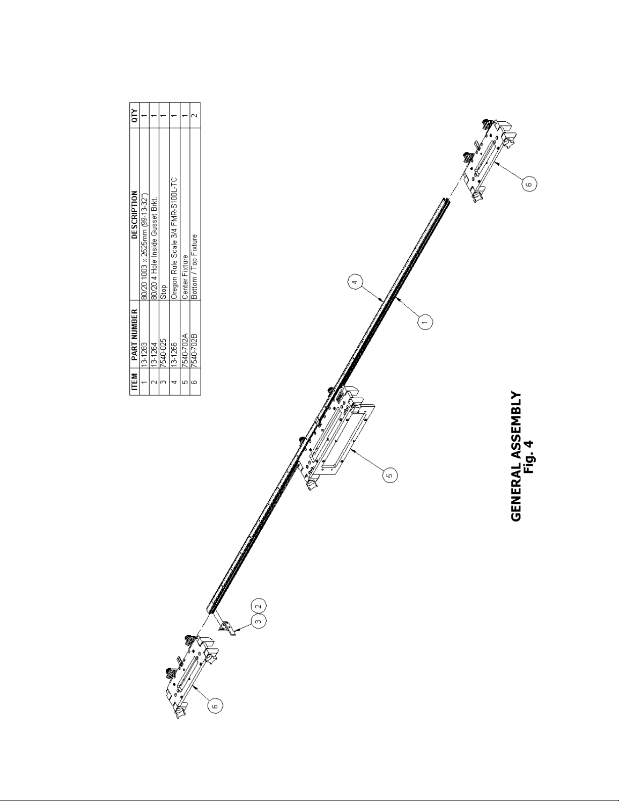
ASSEMBLY AND OPERATION
This fixture is designed to work on square edged doors either 1-3/4” or 2-1/4” thick.
TOOLS REQUIRED FOR SET-UP
• Set of SAE hex keys (1/8”, 5/32” & 3/16”)
BASIC ASSEMBY
The lock installation instructions should be read carefully to determine if the lock
location should be referenced from the top or the bottom of the door. Traditionally, in
prehanging the lock is located from the top of the door, however many multipoint locks
are referenced from the bottom of the door. All three Base Units are symmetrical, so they
will operate from either the top or bottom reference. The Top and Bottom Base Units are
identical, so they will operate in either case.
The following setup is for reference from the bottom of the door.
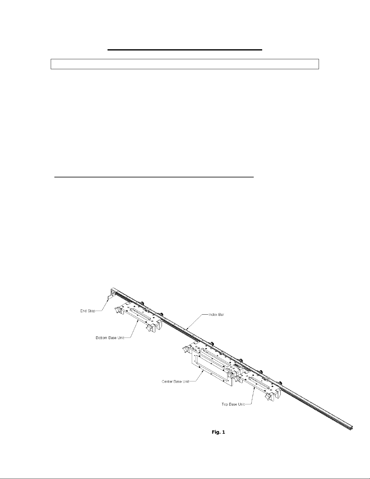
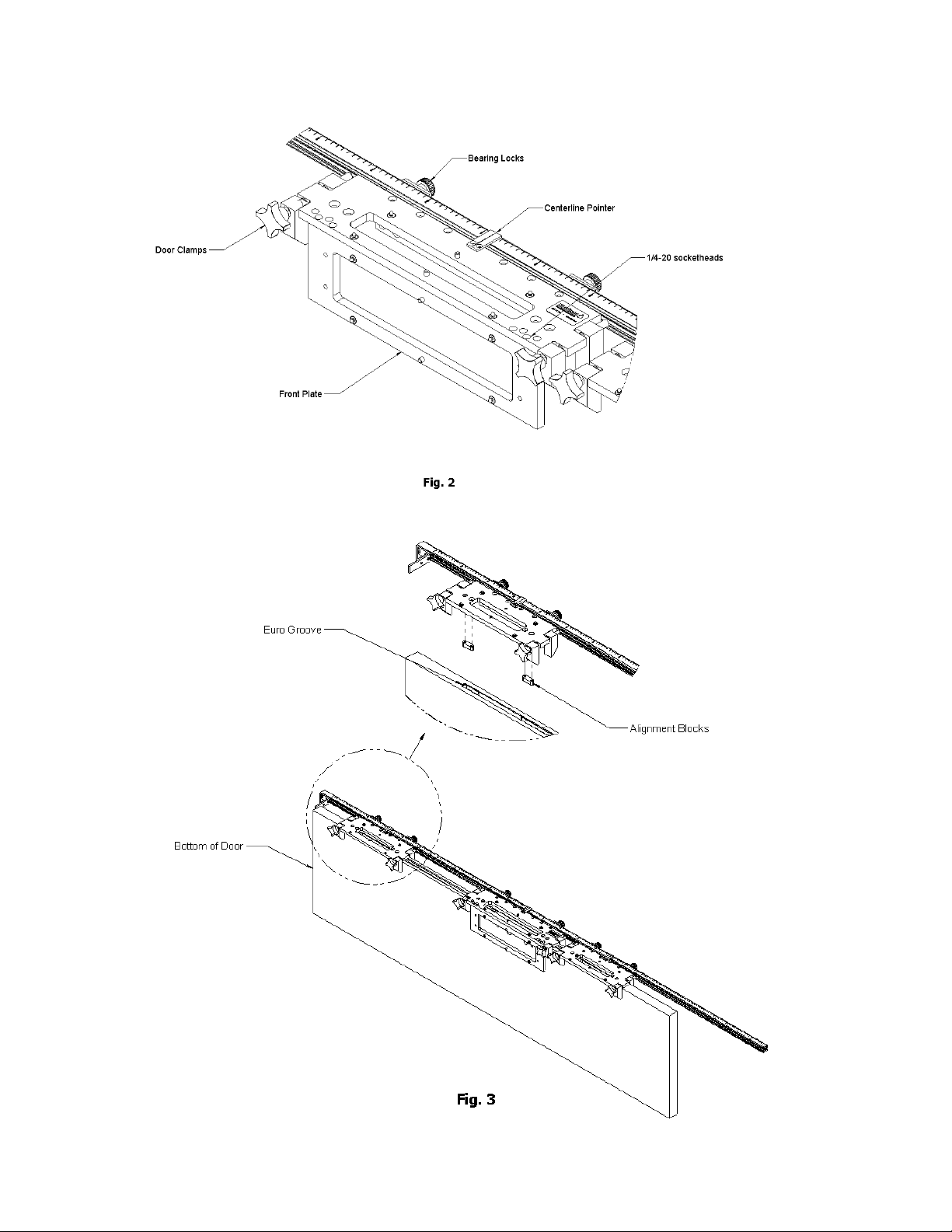
Reference figures 1, 2 & 3
Note: This will position the lock so that the bottom of the faceplate will be flush with the
bottom of the door. The lock location from the top of the door will vary depending upon
the exact height of the door.
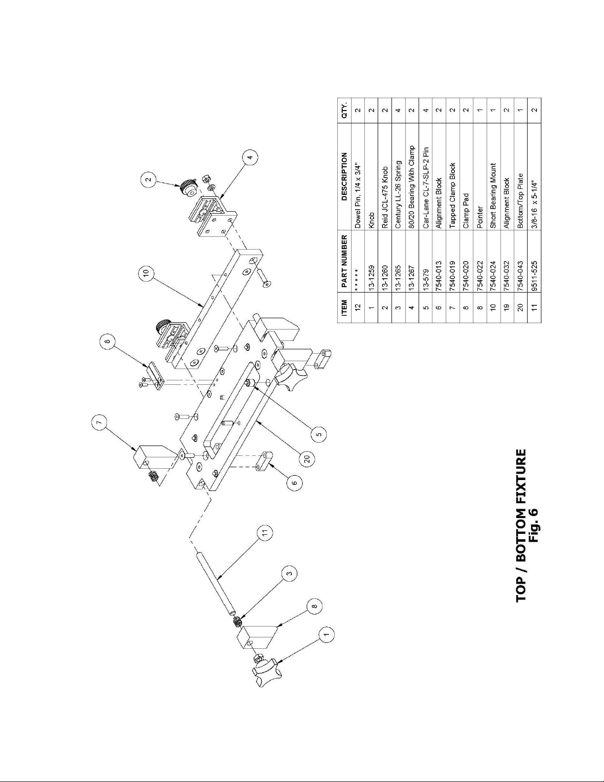
BASE UNITS –The Index Bar should be oriented such that the scale can be read
from the side on which the Base Units are installed. Install the Top, Center and
Bottom Base Units by aligning the 80/20 bearing with clamp (part number 4 in
figures 5 & 6) on the Index Bar.
END STOP –The End Stop should be installed to align with the “0” position on
scale. Use a 5/32”hex key to install screws.

6
The following setup is for reference from the top of the door.
Reference figures 1, 2 & 3
Note: This will position the lock so that the lock handle will always be the same distance
from the top of the door.
BASE UNITS –The Index Bar should be oriented such that the scale can be read
from the side on which the Base Units are installed. Install the Top, Center and
Bottom Base Units by aligning the 80/20 bearing with clamp (part number 4 in
figures 5 & 6) on the Index Bar.
END STOP –The End Stop should be installed to align with the dimension on
the scale that represents the header clearance that is wanted between the top of the
door and the head jamb. Use a 5/32” hex key to install screws.
ALIGNMENT BLOCKS
Alignment blocks are provided to provide accurate alignment of the mortising fixtures to
the Eurogroove (see part number 8 in figure 5 and part number 6 in figure 6). Different
width alignment blocks are available to match the width of other Eurogrooves. Attach the
appropriate alignment blocks to the fixtures with the flathead screws. (3/16” hex key),
ADJUSTMENTS
After assembly is completed, the only adjustment is mortise spacing
Refer to hardware drawings for mortise locations.
MORTISE SPACING
With the Bearing Locks loose, position each fixture according to the specifications for the
hardware being installed. Use the centerline on the Pointer and the scale on the Index Bar
to locate the fixtures. Remember to determine if the measurements are from the top or the
bottom of the door. Tighten both Bearing Locks on each fixture (knurled knobs) to
maintain location relative to the End Stop.
BACKSET
Backset is fixed at 45mm.
TEMPLATES
Typically 4 templates are required for each lock prep; two on the center Base Unit and
one each for the top and bottom Base Units. These snap into position on the ¼” diameter
pins. The templates are marked for orientation to the bottom of the door.
2-1/4” THICK DOORS
When processing 2-1/4” thick doors, the front plate (part number 11 in figure 5) on the
center fixture needs to be moved to the outboard position on part number 9 in figure 5.
Remove the four ¼”-20 socket head cap screws (3/16” hex key), relocate the plate and re-
install the fasteners.
7

8
OPERATION
STEP 1
Use an appropriate tool like the Norfield Stylizer II to mortise the door for the
Eurogroove.
STEP 2
Place the fixture on the door with the End Stop against the end of the door. Ensure that
the fixtures sit flat on the edge of the door with the alignment blocks fully inserted in the
Eurogroove (Detail A in fig. 3). Tighten the Door Clamps on each fixture.
STEP 3
Setup a plunge router with a ½” diameter bit (Norfield P/N WHI10731) and a 13/16”
template guide (Norfield P/N NOR62949). The bit should not project more than ¾” from
the router base when the bit is fully retracted. Determine the mortise depth for the lock
bodies and set a plunge depth stop accordingly. Mortise the pockets starting with the
plunge depth set as shallow as possible. Make multiple passes increasing the plunge
depth on each pass until the desired depth is achieved. Most plunge routers have a
maximum plunge of approximately 2”. If the required depth is greater than approximately
2” make the mortise 2” deep and then reposition the bit in the router to make the deeper
cut. Remove the bit and locking nut with collet. Reposition the router bit so that it is flush
with the top of the collet and reinstall in the router. This should provide a mortise depth
of approximately 3”.
Note: To optimize production time, a second router may be setup for the
deeper mortise requirement.
WARNINGS
DO NOT Install the router bit with the top of the bit below the top of the collet as
the bit could come loose during operation.
DO NOT Insert the router bit through template slot with router running
This will greatly increase the risk of injury to the operator and increase the
potential of permanent damage to templates and the fixture.
STEP 4
Using the plunge router, now in a horizontal position, mortise for the lock function holes.
Again, use multiple passes on each hole until the bit passes through the door.
DOUBLE DOORS
The inactive door in a double or French door unit can be processed as above before the t-
astragal is installed.
STRIKE PLATES
The accurate locations of the strike plates are very important. It is recommended that
their locations should be measured from the top of the door. This will help insure proper
placement in relationship to the clearance between the top of the door and the frame head
jamb. Measure from the top of the door to each of the centerlines on the door mortising
fixture. Be sure to make any adjustment necessary for header clearance. Mark these
locations for the strike plates. You can now use the appropriate tools to mortise for the
strike plates.
STRIKE PLATES ON A JAMB

9
The Norfield MasterLine StrikeMaster (MFG600) can be used to make the strike jamb
mortise for the strike plates
STRIKE PLATES ON A T-ASTRAGAL
The Norfield MasterLine StrikeMaster (MFG600) can be used to make the mortise on
the T-astragal before it is attached to the inactive door OR the Norfield MasterLine T-
Master (MFG650) can be used to make the mortise on the t-astragal after it is attached to
the inactive door. The strike plate templates will work on either MasterLine fixture.
10

11

12
13
Table of contents
Popular Power Tools Accessories manuals by other brands

Atlas Copco
Atlas Copco 4250327580 Instruction supplement

Milwaukee
Milwaukee 5317-DE Operator's manual

Dynabrade
Dynabrade 52061 manual

Metabo
Metabo GED 125 Original instructions

Magswitch
Magswitch MagJig Series Operation and instruction manual

Atlas Copco
Atlas Copco BBD 46WS-6 Safety and operating instructions


RHEINZINK
RHEINZINK CLIPFIX 2.0 Operation, Installation, Maintenance, Spare Parts

SCHUNK
SCHUNK ROTA THW Series Translation of original operating manual

Makita
Makita UB400MP Original instruction manual

Tohnichi
Tohnichi RTDZ Operating instruction

EXAKTOR
EXAKTOR EX40 manual

Milwaukee
Milwaukee 3000 Operator's manual