Norsonic nor145 User manual
nor145
SOUND ANALYSER
INSTRUCTION
MANUAL
INSTRUMENT SOFWARE 3.0
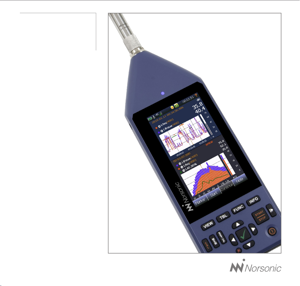
Norsonic has always been at the
forefront introducing new technology
to sound level meters. The Nor145
Sound Analyser sets a new standard in
user-friendliness. Featuring the largest
colour touch screen in a handheld
meter on the market today, the Nor145
provides the user-friendliness of a
smart phone. Further features include
built in web server, LTE and WiFi,
GPS, sound recording, voice and text
notes, sophisticated marker handling
and event triggers in addition to high
resolution time profile, multi-frequency
spectra and on board BA rating
bringing the sophistications normally
found in laboratory instrumentation out
in the field. The instrument is designed
to cover a variety of applications
besides being a sophisticated sound
level meter. This instruction manual
is covering software version 3.0
which with its features address the
noise assessment, noise monitoring
and building acoustics market.

Nor145 User Guide – November 2019 Edition
Im145_1Ed2R0En
Norsonic is a registered trademark of Norsonic AS. All
other brand or product names are trademarks or registered
trademarks of their respective companies. Every effort
has been made to supply complete and accurate informa-
tion. However, Norsonic AS assumes no responsibility for
the use of – nor for the consequential damages of the use
of – this information and/or the instrumentation described
herein. Furthermore Norsonic AS assumes no responsibility
for any infringement of the intellectual property rights of third
parties, wherever applicable, which would result from such
use. Norsonic AS reserves the right to amend any of the
information given in this manual in order to take account of
new developments.
If you wish to communicate with us, please feel welcome.
Our address is:
Norsonic AS, Gunnersbråtan 2, N-3409 Tranby, Norway
Find us on the web: www.norsonic.com
Tel: +47 3285 8900,
E-mail: [email protected]
Copyright © Norsonic AS 2018 All rights reserved

Finding the information you need
The instruction manual describes a fully equipped
instrument. Your version of the instrument may not
have all the optional extensions available. Software
extensions may, however, be installed as retrofit at
any time, However, hardware extensions like the
LTE, WiFi and GPS cannot be installed as retrofit.
Denotes
Some denotes are used in the manual to ease the use
and distinguish a keyboard key, a soft key or a menu.
VIEW denotes the View button found on the rubber
keyboard.
Stop denotes a soft key mostly found in the lower line
of the display.
Instrument denotes a menu point.
Thank you for choosing Norsonic!
The Nor145 has been designed to give you many years
of safe, reliable operation.
Your approach to the Nor145 documentation depends
on what you want to do and how much you already know.
This manual is divided into several sections plus an
index. Each section provides useful and in depth infor-
mation about the available features. Depending on your
requirements and your familiarity with measurements
as such, you may find that you use some parts of this
manual quite often and others not at all.
A brief introduction of the user philosophy and use of
the instrument is described in chapter 2. We recom-
mend reading this chapter before use, and as a mini-
mum, reading the safety instructions and precautions
in chapter 1.
If you do not have this manual at hand, useful help is
found in context sensitive help function in the instrument.
In most pictures there is a red question mark “?“ in the
upper right corner of the display. Tap it to access the
help function.


i
Norsonic Nor145
Instruction Manual
Contents
Chapter 1 Important information�����������������������������������������������������������������������������������������������������1
Safety instructions .............................................................................................................................. 1
Precautions......................................................................................................................................... 2
Chapter 2 Taking a closer look at the instrument��������������������������������������������������������������������������4
Switching ON/OFF ............................................................................................................................. 5
Keyboard ........................................................................................................................................... 5
Touch sensitive screen....................................................................................................................... 7
The Main Status LED.......................................................................................................................... 8
Input and output connectors.............................................................................................................. 9
On the use of the internal battery vs. external DC ............................................................................. 9
Charging the Internal Battery ............................................................................................................10
If power fails ......................................................................................................................................10
Power saving - maximize your battery power ...................................................................................10
Optional extensions...........................................................................................................................11
Software maintenance.......................................................................................................................11
Chapter 3 Your first measurement ������������������������������������������������������������������������������������������������12
Turn on the instrument.......................................................................................................................12
Select the transducer ........................................................................................................................12
Check the calibration.........................................................................................................................12
Select a standard set up ...................................................................................................................12
Start and Stop of the measurement ..................................................................................................12
Saving the measurement to the memory ..........................................................................................13
Reducing the influence of the operator.............................................................................................13
Removing the influence of the instrument itself ................................................................................13
Limiting the influence of wind and dust ............................................................................................13

ii Contents
Chapter 4 The measurement functions available������������������������������������������������������������������������14
Chapter 5 Setting up the analyser�������������������������������������������������������������������������������������������������19
The organisation of the display .........................................................................................................19
The status bar ............................................................................................................................ 20
Symbol # 1 Battery gauge / external power .............................................................................. 20
Symbol # 2; Overload indication.................................................................................................21
Symbol # 7, Measurement status................................................................................................21
Symbol # 8, Application mode....................................................................................................21
The soft key bar...........................................................................................................................21
The measurement picture .......................................................................................................... 22
On-screen menus............................................................................................................................. 23
Activate and deactivate the result displays ................................................................................24
Cursor handling.......................................................................................................................... 25
The main menu system - an overview.............................................................................................. 25
On/Off/Available/Disabled indication........................................................................................ 26
Chapter 6 Selecting the different views and the parameters to display�����������������������������������27
Function selection – selecting the measurement parameters ..........................................................31
SPL Live in ended mode ................................................................................................................. 33
Numerical tables .............................................................................................................................. 33
Chapter 7 Input selection Menu ����������������������������������������������������������������������������������������������������34
The Sound channel menu ................................................................................................................ 35
The Transducer menu ................................................................................................................ 36
Adding a new sensor ................................................................................................................. 39
Preamplifier selection................................................................................................................. 39
Using other transducers................................................................................................................... 39
Chapter 8 Calibrating the instrument - field check�����������������������������������������������������������������������������40
When to calibrate ....................................................................................................................... 40
Carrying out the field check / calibration................................................................................... 40
Calibrating a vibration sensor ................................................................................................... 42
Microphone check............................................................................................................................ 43

iii
Norsonic Nor145
Instruction Manual
Chapter 9 Measurement Setup Menu��������������������������������������������������������������������������������������������44
High-pass input filter.................................................................................................................. 45
Weather Station...........................................................................................................................47
Chapter 10 FFT ����������������������������������������������������������������������������������������������������������������������������������48
Introduction....................................................................................................................................... 48
How to select FFT ............................................................................................................................ 48
Making a measurement.................................................................................................................... 48
Calibration ........................................................................................................................................ 49
Corrections ....................................................................................................................................... 49
Chapter 11 Trigger Selection Menu�������������������������������������������������������������������������������������������������50
Global Trigger................................................................................................................................... 50
The Event Trigger ............................................................................................................................. 53
Chapter 12 Working with Markers ���������������������������������������������������������������������������������������������������56
Setting up Markers - the Marker Setup menu .................................................................................. 56
System specified markers................................................................................................................ 57
Adding a marker to an ongoing measurement ................................................................................ 58
Working with markers - post processing.......................................................................................... 58
Chapter 13 Recording the sound - Audio record and replay ���������������������������������������������������������������� 59
Making a recording .......................................................................................................................... 60
Listening - replaying an audio recording ..........................................................................................61
Insert a reference tone as a recording..............................................................................................61
Chapter 14 Camera ���������������������������������������������������������������������������������������������������������������������������62
Device camera ................................................................................................................................. 62
IP camera. ....................................................................................................................................... 62
Chapter 15 Voice and Text notes�����������������������������������������������������������������������������������������������������64
Adding text and voice notes............................................................................................................. 64
Retrieving text and voice notes. ....................................................................................................... 64
Chapter 16 Pausing and resuming a measurement ����������������������������������������������������������������������66
The difference between a “Pause” and a “Hold” function............................................................... 67

iv Contents
Chapter 17 Storing a measurement - Memory Organising Menu ��������������������������������������������������68
File name .......................................................................................................................................... 69
Unique Measurement identifier ........................................................................................................ 70
Save and Manage Measurement setup ........................................................................................... 70
Write Protected Setup....................................................................................................................... 70
Rename, Delete, Move ..................................................................................................................... 70
Set Factory default.............................................................................................................................71
Save Debug Log................................................................................................................................71
Chapter 18 Application Selection Menu - Predefined Setups������������������������������������������������������72
Creating a user defined setup.......................................................................................................... 73
Chapter 19 Signal Generator (Optional)����������������������������������������������������������������������������������������� 74
Chapter 20 Building Acoustic����������������������������������������������������������������������������������������������������������75
Introduction....................................................................................................................................... 75
Measurement Mode ..........................................................................................................................76
Display views in Measurement Mode .........................................................................................76
The views ....................................................................................................................................76
On-screen menus ...................................................................................................................... 78
Setup ................................................................................................................................................ 78
Input - Setup............................................................................................................................... 78
Type - Setup ............................................................................................................................... 79
Level - Setup .............................................................................................................................. 79
Reverberation - Setup) ............................................................................................................... 80
Rating – Setup.............................................................................................................................81
Standard:.....................................................................................................................................81
Source .........................................................................................................................................81
Receiving ................................................................................................................................... 82
Test Specimen............................................................................................................................ 82
Various parameters ................................................................................................................... 83
Signal Generator - Setup ........................................................................................................... 83
Memory – Setup......................................................................................................................... 83
Making the Level measurements ..................................................................................................... 84
Making the Background noise measurements ................................................................................ 85
Making the Reverberation time measurements ............................................................................... 86

v
Norsonic Nor145
Instruction Manual
Project Mode ..............................................................................................................................87
Display views in Project Mode .............................................................................................87
Rating views 1 - 4 ................................................................................................................89
Rating View-1 .......................................................................................................................89
Rating View-2 .......................................................................................................................90
Rating View-3 .......................................................................................................................90
Rating View-4 .......................................................................................................................90
Measurements views 1 – 4...................................................................................................91
View 1 - 4 for reverberation time measurements: ................................................................92
View 1 - 4 for receiving room measurements: .....................................................................92
Measurement View-1 ...........................................................................................................93
Measurement View-2 ...........................................................................................................94
Measurement View-3 ...........................................................................................................95
Measurement View-4 ...........................................................................................................96
Exclude measurement positions ................................................................................................97
Adjust reverberation decay line..................................................................................................97
Start a new project .....................................................................................................................98
Continue an existing project.......................................................................................................98
Chapter 21 Instrument Specific Setup��������������������������������������������������������������������������������������99
Digital and Analog I/O................................................................................................................99
Digital Output .....................................................................................................................100
Headset..............................................................................................................................100
Analog Output....................................................................................................................100
Communication ........................................................................................................................101
Security ..............................................................................................................................103
Reference Tone ........................................................................................................................106
Power Settings..........................................................................................................................107
Instrument Name......................................................................................................................107
Date and Time ..........................................................................................................................107
Language...........................................................................................................................109
Number Format ..................................................................................................................109
About..................................................................................................................................109
Install new software, service pack or new fonts.......................................................................109
The software license system .................................................................................................... 110
Installing new options............................................................................................................... 111
Activate evaluation license ....................................................................................................... 111

vi Contents
Chapter 22 Norsonic software������������������������������������������������������������������������������������������������������� 112
NorRemote Nor1050 - option 11 .....................................................................................................112
Using the program – Nor145 ...........................................................................................................113
Main display ..............................................................................................................................113
Editing views settings................................................................................................................115
Operating in the graphs ............................................................................................................116
Editing parameters in views ......................................................................................................116
Editing markers .........................................................................................................................117
Configuration ...................................................................................................................................118
Configuration menu...................................................................................................................118
Measurement configuration ......................................................................................................118
Timing........................................................................................................................................119
Functions...................................................................................................................................119
Filter...........................................................................................................................................119
Recording..................................................................................................................................119
Saving configuration .................................................................................................................119
Trigger configuration.................................................................................................................119
Camera......................................................................................................................................122
Alarm channels, only for monitoring .........................................................................................123
Configuration.............................................................................................................................124
Date and Time...........................................................................................................................124
User information........................................................................................................................124
Chapter 23 Technical Specifications ��������������������������������������������������������������������������������������������126
Firmware version .............................................................................................................................126
Type of instrument ...........................................................................................................................126
Analog inputs...................................................................................................................................127
Input connector.........................................................................................................................127
Microphone input socket (outside view)...................................................................................127
High-pass input filter .......................................................................................................................128
Nor1227 technical data ............................................................................................................128
Preamplifier..................................................................................................................................... 129
Nor1209 data ........................................................................................................................... 129
Nor1209 Technical data in combination with Nor145;............................................................. 129
Windscreen ............................................................................................................................. 129
Cables and cable length ................................................................................................................ 130

vii
Norsonic Nor145
Instruction Manual
Acoustical data for Nor1227 and Nor1209 mounted on Nor145........................................................... 130
Reference direction: .............................................................................................................................. 130
Microphone Reference Point ................................................................................................................. 130
Corrections used for verification and stating conformance to EN/IEC 61672-1 ................................... 131
Detailed table for level corrections according to IEC 62585................................................................. 132
Directional response – Horizontal.......................................................................................................... 136
Directional response - Vertical............................................................................................................... 138
Directional response – Horizontal with Wind Screen............................................................................. 140
Directional response – Vertical with Wind Screen ................................................................................. 142
Verification of the free field response ......................................................................................................... 144
Analog to digital converters ......................................................................................................................... 144
Frequency weightings .................................................................................................................................. 144
Weighting networks:............................................................................................................................... 144
Filters...................................................................................................................................................... 144
Construction........................................................................................................................................... 144
Frequency range:................................................................................................................................... 145
Exact mid-band frequencies.................................................................................................................. 145
Reference attenuation:........................................................................................................................... 145
Operation ............................................................................................................................................... 145
Table of octave and one-third octave band filters ................................................................................. 145
Octave frequencies................................................................................................................................ 146
One-third-octave frequencies................................................................................................................ 146
FFT................................................................................................................................................................ 147
Level detector............................................................................................................................................... 147
Detector type.......................................................................................................................................... 147
Crest factor capability ............................................................................................................................ 147
Overload indication................................................................................................................................ 148
Under-range indication .......................................................................................................................... 148
Time weightings and measured functions............................................................................................. 148
Level distribution .......................................................................................................................................... 148
Statistics ................................................................................................................................................. 149
Indication on the screen of the Nor145........................................................................................................ 149
Indication range............................................................................................................................................ 150
Self-noise levels ........................................................................................................................................... 150
Electric self-noise ......................................................................................................................................... 150
Acoustic self-noise................................................................................................................................. 150

viii Contents
Considerations for low noise measurements............................................................................151
Measurement duration and resolution ...........................................................................................151
Measurement ranges ......................................................................................................................151
Total range for measurement of A-weighted levels .................................................................151
Total range for measurement of C-weighted levels ................................................................152
Total range for measurement of Z-weighted levels ..................................................................152
Measurement range for C-weighted peak levels .....................................................................152
The Nor145 used for electrical measurements.............................................................................. 153
Electrical verification measurements ............................................................................................. 153
Power supply .................................................................................................................................. 153
Internal battery ........................................................................................................................ 153
Power consumption.................................................................................................................. 154
External DC / Charging input................................................................................................... 154
Mains adapter .......................................................................................................................... 154
Display............................................................................................................................................ 154
Keyboard ........................................................................................................................................ 154
Adjustment of indicated levels ....................................................................................................... 155
Random response.................................................................................................................... 155
Windscreen .............................................................................................................................. 155
Diffraction around the instrument casing ...................................................................................... 155
The general I/O socket................................................................................................................... 156
Signal output – Noise generator .............................................................................................. 156
Signal output – Microphone signal .......................................................................................... 156
Serial I/O port........................................................................................................................... 156
Digital inputs ............................................................................................................................ 156
Digital output control lines ........................................................................................................157
Headset input and output socket....................................................................................................157
LAN interface...................................................................................................................................157
USB interface ................................................................................................................................. 158
Wi-Fi and HotSpot (optional) ......................................................................................................... 158
Wireless LTE modem (optional) ..................................................................................................... 158
GPS (optional) ................................................................................................................................ 158
Data /Setup storage ....................................................................................................................... 158
SD-card.................................................................................................................................... 158
Internal memory ....................................................................................................................... 158

ix
Norsonic Nor145
Instruction Manual
Appendix A Index �����������������������������������������������������������������������������������������������������������������������������163
Appendix B Supplier’s Declaration of Conformity
47 CFR § 2�1077 Compliance Information����������������������������������������������������������������� 171
Appendix C Battery Certification N38�3 Transport of Dangerous Goods ������������������������������� 172
Appendix D Declaration of Conformity������������������������������������������������������������������������������������������175
Environmental conditions ................................................................................................................159
Warm-up time ..................................................................................................................................159
Changes in the environmental conditions.......................................................................................159
Sensitivity to static pressure............................................................................................................159
Sensitivity for vibration.....................................................................................................................159
Sensitivity for magnetic fields......................................................................................................... 160
Sensitivity for radio frequencies ..................................................................................................... 160
Emission of radio frequencies ........................................................................................................ 160
Sensitivity for AC power frequency ................................................................................................ 160
Recovery after electrostatic discharge ...........................................................................................161
Size and weight ...............................................................................................................................161


nor145
SOUND ANALYSER


1
Norsonic Nor145
Instruction Manual
Important information
Please read all safety, precaution and storage information
before use. These sections contain vital information to
maintain safety and warranty.
Safety instructions
• Read these instructions.
• Follow all warnings and safety instructions.
• Do not use the instrument in rain or moisture.
• Keep the instrument out of corrosive atmosphere
and do not use it in a hazardous area.
• Clean the instrument only with dry cloth, except for
the display where special wipes are available.
• Do not place this instrument near any heat sources
such as radiators, heat registers, stoves, or other
apparatus that produce heat.
• Use the original mains adapter supplied with the
instrument, Nor345A or Nor345B - both are in use.
• The internal battery is a Li-ion type. Make sure it is
recycled properly if it is going to be replaced
• Make sure the instrument and any accessories are
not damaged before use.
• Only use attachments/accessories allowed or
specified by Norsonic AS.
• Be careful when using the instrument on a tripod or
in combination with a rotating boom.
• Unplug this instrument during lightning storms or
when unused for long periods of time.
• Refer all servicing to qualified service personnel.
Caution!
Never expose the batteries to temperatures out-
side maximum operation temperature range;
-10 °C / 14 °F to +50 °C / 122 °F.
Maximum storage temperature range is -30 °C /
-22 °F to +50 °C / 122 °F. Room temperature is
recommended for long time storage. Always fully
charge the batteries before storage. Recharge
batteries fully every third month for long time
storage.
Never use mechanical damaged batteries.
Shipment of batteries via air or brought as hand
luggage / luggage are governed by IATA /
UN3481, PI 967 section II when shipped as a
part of the instrument and PI 966 part II if shipped
separate. See IATA standard for labelling the
parcel and to acquire latest information about
shipment instructions.
NOTE Damaged batteries are strictly prohibited to
be shipped as airfreight or brought onto a plain as
hand luggage or checked in luggage.

2Chapter 1
Important information
Failing to follow these precautions may damage the
batteries, void the warranty conditions and/or lead to
hazardous situations.
There are NO user-serviceable parts inside. Servicing
is required when the instrument has been damaged in
any way, such as power failure, battery failure or any
plug is damaged, liquid has been spilled or objects
have fallen into the apparatus, the instrument has been
exposed to rain or moisture, does not operate normally,
or has been dropped.
Important notice! Never block the tiny hole located
at above the knurled screw on the preamplifier.
This is the ventilation hole to equalize static
pressure difference in the microphone. Blocking this
hole may give wrong measurement results.
Precautions
You probably already know it but…
…. Always turn on the password protection if you
connect the instrument to a public or unsecured
network. If not, the instrument is an easy victim for
cyber-attack. It is a good practice to always use a FTP
password regardless of the connection environment.
Also, enable a password protection for the NorRemote
program. “Security” on page 103.
… the microphone is an especially fragile device. It is
easily broken, so take care.
…. always keep the microphone cartridge mounted on
the preamplifier. This is the safest way to avoid damage
and access of dirt on the contact pin between the pre-
amplifier and microphone cartridge.
… keep the instrument in its carrying case, don’t leave
it everywhere.
… even the instrument is a field instrument, prevent it
from direct contact with dust and moisture.
… Nor145 is a measurement instrument; protect it from
impacts and strong vibration.
… never store the instrument with empty batteries. This
may permanent damage the batteries.
… fully recharge batteries every third month if the
instrument is not in use.
… always calibrate the microphone before and after a
measurement.
… send the instrument for verification at an accredited
laboratory minimum every 24 months.

3
Norsonic Nor145
Instruction Manual
This equipment has been tested and found to
comply with the limits for a Class B digital device,
pursuant to part 15 of the FCC Rules. These limits
are designed to provide reasonable protection
against harmful interference in a residential instal-
lation. This equipment generates, uses and can
radiate radio frequency energy and, if not installed
and used in accordance with the instructions, may
cause harmful interference to radio communica-
tions. However, there is no guarantee that interfer-
ence will not occur in a particular installation.
If this equipment does cause harmful interference
to radio or television reception, which can be
determined by turning the equipment off and on,
the user is encouraged to try to correct the inter-
ference by one or more of the following measures:
- Reorient or relocate the receiving antenna.
- Increase the separation between the equipment
and receiver.
- Connect the equipment into an outlet on a
circuit different from that to which the receiver
is connected.
- Consult the dealer or an experienced radio/TV
technician for help.
4Chapter 2
Taking a closer look at Nor150
Norsonic Nor145
Instruction Manual
Taking a closer look at
the instrument
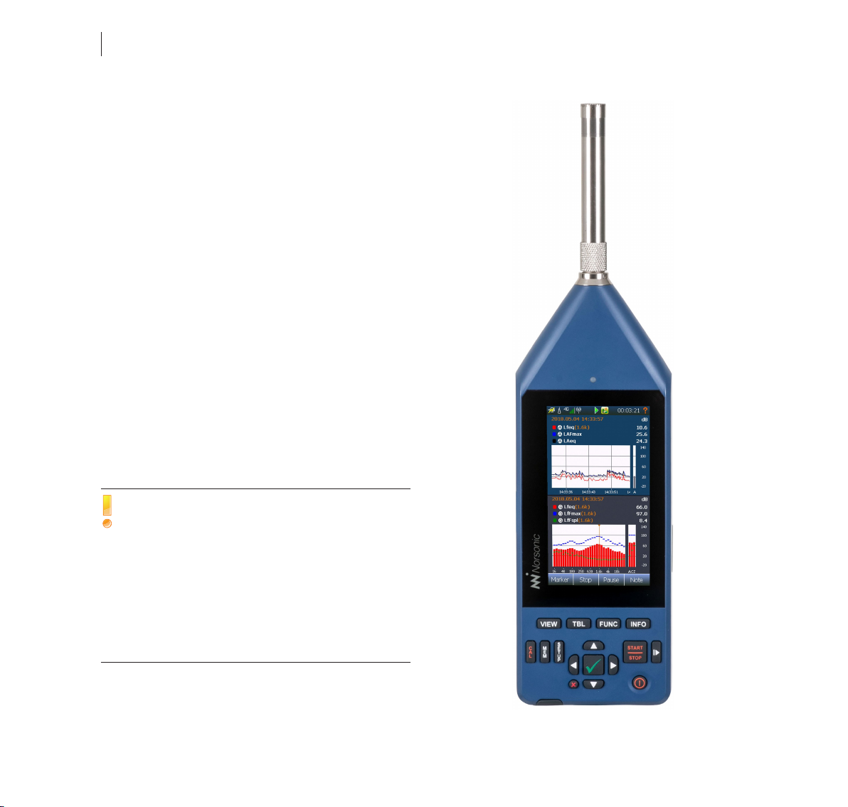
Be sure to take utmost care when mounting a micro-
phone cartridge onto a preamplifier. Finger tight only!
The picture shows the Nor145 fitted with the standard
preamplifier Nor1209 and the microphone Nor1227.
The instrument is powered from an internal recharge-
able Li-ion battery pack. The battery is charged when
leaving the factory, but due to self-discharge, you may
experience the battery gauge shows a lower value than
full. The batteries will be charged once the instrument
is connected to mains via the supplied mains adapter
Nor345A
Always keep the microphone cartridge mounted on
the preamplifier. This is the safest way to avoid
damage and access of dirt on the contact pin
between the preamplifier and microphone cartridge.
The preamplifier input has extremely high input
impedance (10 Giga ohms) in order not to load the
microphone cartridge. Hence, dust, finger prints or
other types of contamination may change the
sensitivity of the microphone, especially at high
humidity.
Other manuals for nor145
2
Table of contents
Other Norsonic Measuring Instrument manuals

Norsonic
Norsonic 140 User manual

Norsonic
Norsonic nor103 User manual

Norsonic
Norsonic NOR150 User manual

Norsonic
Norsonic Nor1545 Instruction Manual

Norsonic
Norsonic nor140 Operating and maintenance manual

Norsonic
Norsonic nor121 User manual

Norsonic
Norsonic nor145 User manual

Norsonic
Norsonic nor140 User manual

Norsonic
Norsonic nor118 User manual

Norsonic
Norsonic NOR150 User manual


