Nortech F20 User manual

F20
Twin Earth Fault Indicator
© Nortech Management Ltd, United Kingdom
Page 2 of 16
Publication Notice
Copyright © Nortech Management Limited (NML). All rights reserved. No part of this publication
may be reproduced, stored in a retrieval system, or transmitted in any form or by any means,
including photocopying, electronic, mechanical, recording or otherwise, without the prior written
permission of the copyright holder.
NML provide this document as is, without warranty of any kind either expressed or implied
including, but not limited to, the implied warranties of merchantability and fitness for a particular
purpose. NML may make changes or improvements in the software, equipment, or specifications
described in this document at any time and without notice. These changes may be incorporated in
new releases of this document.
This publication could contain technical inaccuracies or typographical errors. NML shall not be
liable for any damages (including, but not limited to, consequential, indirect or incidental, special
damages or loss of profits or data) even if NML have been informed of their potential occurrence,
arising out of or in connection with this document or its use.
English Edition
IBM PC is a trademark of International Business Machines Inc.
Windows is a trademark of Microsoft Corporation.
All other trademark names used in this manual are hereby acknowledged.

F20
Twin Earth Fault Indicator
© Nortech Management Ltd, United Kingdom
Page 3 of 16
Contents
1Description.......................................................................................4
2Operation.........................................................................................5
2.1 Local Indication ...........................................................................5
2.2 Indication Period .........................................................................5
2.3 Reset .........................................................................................5
2.4 Current Transformers ...................................................................5
2.5 Sensitivity ..................................................................................5
2.6 Test ...........................................................................................6
3Operation worked examples ...............................................................7
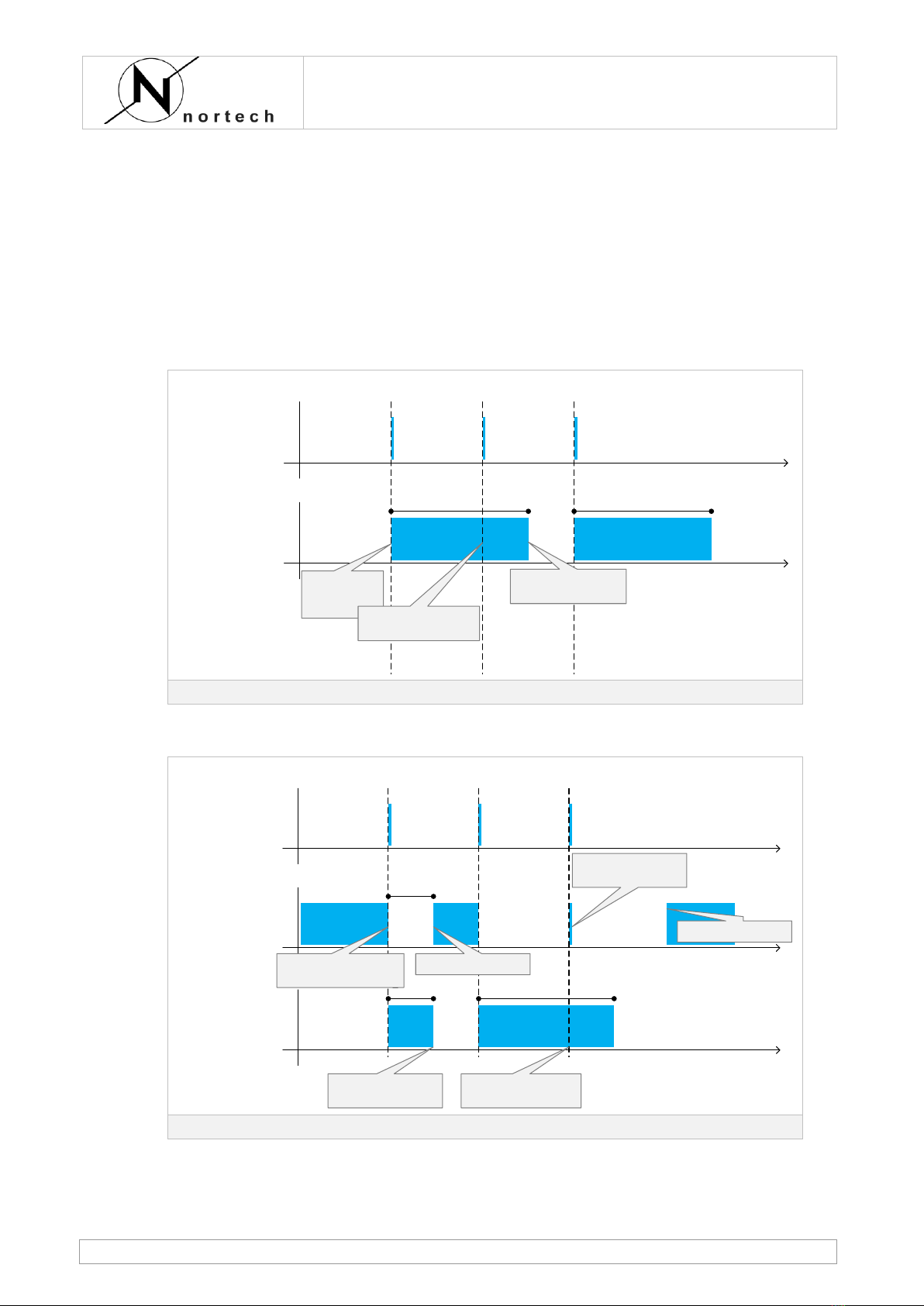
3.1 Indication with no electrical reset ..................................................7
3.2 Indication with AC reset signal ......................................................7
3.3 Indication with DC reset signal ......................................................8
4Installation.......................................................................................9
4.1 Physical......................................................................................9
4.2 CT earthing.................................................................................9
4.3 CT connections .......................................................................... 10
4.4 Wiring connections .................................................................... 11
4.5 Enclosure Mounting.................................................................... 12
4.5.1 Enclosure options................................................................. 12
5Maintenance ................................................................................... 13
5.1 Technical Assistance .................................................................. 13
5.2 Simple Test............................................................................... 13
5.3 Primary Injection ....................................................................... 13
5.4 Replace battery ......................................................................... 13
5.5 Recycling.................................................................................. 13
6Specification................................................................................... 14
6.1 General .................................................................................... 14
6.2 EMC ......................................................................................... 14
6.3 Environmental........................................................................... 15
7Notices .......................................................................................... 16

F20
Twin Earth Fault Indicator
© Nortech Management Ltd, United Kingdom
Page 4 of 16
1Description
The F20 Twin Earth Fault Indicator enables electricity distribution network
engineers to quickly determine which section of the underground MV network
is responsible for the interruption of consumer supplies.
The F20 has two independent Earth Fault (EF) elements. This allows the F20
to be used to monitor both the incoming and outgoing cables at a Ring Main
Unit site on the distribution network.
An indication of the passage of fault current is given by a flashing LED for a
pre-set time period. At the same time the relay contacts operate giving an
electrical remote alarm.
On completion of the time period the unit will automatically self reset and is
then ready to detect subsequent faults. The F20 may also be manually reset,
remotely reset via a telecontrol DC reset signal or on restoration of AC
supplies.
Each of the EF elements is available for use with either a core balance CT or
three phase CTs. The CT arrangements are factory set.
A lithium battery provides power to the unit. The battery will provide up to 20
years life between changes.
A 12-24V dc supply can be connected as an alternative to the lithium battery.

F20
Twin Earth Fault Indicator
© Nortech Management Ltd, United Kingdom
Page 5 of 16
2Operation
2.1 Local Indication
On detection of fault current above the earth fault sensitivity threshold and for
the minimum required duration the F20 will operate as follows: -
1Flashing LED with an interval of 1.5 seconds for the duration of the
indicating period.
2Volt free contacts operate during the indicating period.
2.2 Indication Period
The default value is 3 hours flashing when a fault is detected.
Different indication periods may be selected to suit local requirements either
at time of order or in the field using a laptop and the F20 Field Support Kit.
2.3 Reset
Automatic
The indicator returns to the ready state (LED not flashing, volt-free contacts
reset, ready to detect fault current) after the indication period has elapsed.
Each Earth fault element has its own reset timer.
Manual
The F20 may be reset early, at any time during the indication period, by
pressing the RESET button on the front of the F20. Once the button is
released the F20 will be reset to the ready state. Each Earth fault element
has its own reset button.
Electrical
The F20 may be reset early, at any time during the indication period, by either
a DC pulse (from a telecontrol RTU) or on restoration of a local AC supply.
Electrical reset signals reset both EF elements.
2.4 Current Transformers
The CT combinations to be used is a factory option –check with Nortech for
suitable part numbers. The F20 is designed for use with either:
Core Balanced CT
One 60/1 core balance CT having a minimum rating of 1.5VA and an accuracy
of 10% up to 4 times primary current (10P4).
Switchgear Phase CTs
Three single phase CT (typically 500:1) supplied with the Ring Main Unit.
These CT arrangements should be tested by Nortech to confirm suitability
prior to use.
2.5 Sensitivity
The F20 is designed to operate at 45 Amps primary current. Exact operating
sensitivity can be affected by the model of CT used and fault characteristic.

F20
Twin Earth Fault Indicator
© Nortech Management Ltd, United Kingdom
Page 6 of 16
The F20 requires the fault to be present for a minimum of 50ms, the operating
curve can be assumed to be close to definite time.
2.6 Test
A simple manual test of the F20 is achieved by pressing each of the TEST
buttons.
When pressed the associated LED will flash, however the output contacts will
not operate.
This simple test proves the processor, LED, test button and battery are
healthy. It does not test the integrity of the CT connections or output
contacts.
A primary injection into the CT arrangement is the best local test available.
Nortech supply a portable battery powered test set for this purpose.

F20
Twin Earth Fault Indicator
© Nortech Management Ltd, United Kingdom
Page 7 of 16
3Operation worked examples
The examples below illustrate how applying electrical reset can affect
detection and indication of faults.
The examples assume the F20 is configured with a 3 hour indication period
and consider only one Earth Fault element.
The three faults occur at 2 hour intervals. After Fault 1 supplies are lost for 1
hour. After Fault 2 supplies are lost for 5 hours except for a few milliseconds
while Fault 3 is on the network.
3.1 Indication with no electrical reset
time
fault current
time
LED indication
and relay contacts
3 hours 3 hours
Fault 1 Fault 2 Fault 3
Unit starts
indication for
fault 1 Fault 2 not detected as
already indicating
Reset at end of 3 hour
timer
Indications with timer reset only
3.2 Indication with AC reset signal
time
fault current
time
LED indication
and relay contacts
time
AC supply status
1 hour 3 hours
1 hour
Fault 1 Fault 2 Fault 3
AC supply restored
Reset occurs 10 seconds
after AC is restored
No Reset as AC is on for
<10 seconds
AC supply lost when fault
occurs
AC supply restored
AC on for less than 10
seconds
Indications with AC reset connected

F20
Twin Earth Fault Indicator
© Nortech Management Ltd, United Kingdom
Page 8 of 16
3.3 Indication with DC reset signal
time
fault current
time
LED indication
and relay contacts
time
DC reset signal
Fault 1 Fault 2 Fault 3
In all cases RTU sends DC
reset signal as soon as F20
indication is detected. F20
resets within 1 second of
DC reset signal
Indications with DC reset connected

F20
Twin Earth Fault Indicator
© Nortech Management Ltd, United Kingdom
Page 9 of 16
4Installation
4.1 Physical
The F20 has an outer polycarbonate enclosure. The electronics are
encapsulated in the lid. The LED and buttons are located on the front of the
F20.
The F20 should be mounted for good visibility and as close as practical to the
CT.
4.2 CT earthing
For safety reasons, it is normal practice for the CT to be mounted in a
position over the cable sheath or screening tape, and in accordance
with local safety regulations.
When an earth fault occurs in a cable network the majority of return current
will flow through the cable sheath, thus resulting in a null output from the
core balance CT, as shown in the figure below.
INCORRECT Earthing
Incorrect Earthing
This effect can be prevented if the cable earthing connection between the
cable and adjacent switch is routed through the core balance CT shown below.
Correct Earthing
Correct Earthing
Where single core cables are used, each sheath earth-wire must be routed
through the single core balance CT.

F20
Twin Earth Fault Indicator
© Nortech Management Ltd, United Kingdom
Page 10 of 16
4.3 CT connections
The CT arrangement the F20 will be used with is a factory set option.
Wire the summated output from the
CT secondary’s to the CT terminals
of the F20.
The current transformers should be
connected as shown in the diagram,
it is important that the polarities are
as shown.
Wire the output from the CT secondary
to the CT terminals of the F20.
3 phase CT connections
Single core balanced CT connection

F20
Twin Earth Fault Indicator
© Nortech Management Ltd, United Kingdom
Page 11 of 16
4.4 Wiring connections
F20 wiring connections are provided as screw terminals inside the lid of the
enclosure.
If mounted within a cable termination enclosure, one core of the CT should be
connected to earth for safety.
Battery
EF 1 EF 2 EF 1 EF 2 RESET
L N+ -
COM
CT PWR
CT
3 x 500:1 60:1
+ -
12-24V 90-240V
ALARM ALARM
DC AC
12-24V
DC
CT1
CT2
CT3
5 63 41 2 11 129 107 8 17 1815 1613 14
Power Supply
If it is not already connected the
battery should be plugged in.
As an alternative to battery
power the F20 may be powered
from an external 12-24V DC
source connected across
terminals 7 & 8, observe correct
polarity.
AC Reset
Apply 90V-240V ac between
terminals 17 & 18 for 10s to
reset both of the EF elements.
Observe correct polarity.
DC Reset
Apply 12V-24V dc between
terminals 15 & 16 for 1s to reset
both of the EF elements.
Observe correct polarity.
EF element 1: CT connections
Observe the CT ratio expected (in the
example above 500:1)
Connect CT secondary positive
outputs to terminals 1, 2 & 3.
Terminals 1, 2 & 3 are internally
connected together on the F20 pcb.
Connect CT secondary common
output to terminal 4.
EF element 1: Output contacts (Alarm)
Circuit between terminals 9 & 10 is
normally closed and will open when
EF element 1 is indicating.
Circuit between terminals 10 & 11 is
normally open and will close when EF
element 1 is indicating.
EF element 2: CT connections
Observe the CT ratio expected (in the
example above 60:1)
Connect CT secondary output to
terminals 5 & 6.
EF element 2: Output contacts (Alarm)
Circuit between terminals 12 & 13 is
normally closed and will open when
EF element 2 is indicating.
Circuit between terminals 13 & 14 is
normally open and will close when EF
element 2 is indicating.
F20 wiring connections

F20
Twin Earth Fault Indicator
© Nortech Management Ltd, United Kingdom
Page 12 of 16
4.5 Enclosure Mounting
The enclosure has four 4mm fixing holes suitable for use mounting the F20 on
a wall or switchgear bracket.
120.0mm
122.0mm
90.0mm 4 off Mounting holes
110.0mm
Rear view of F20 enclosure
F20 enclosure fixing holes
4.5.1 Enclosure options
The F20 can be supplied with custom drillings, cable entry glands and
blanking.
The F20 can be supplied with different depth enclosures if required.
An optional switchgear leg mounting bracket is available.
Please contact Nortech with your requirements or ask for a full list of available
part numbers.

F20
Twin Earth Fault Indicator
© Nortech Management Ltd, United Kingdom
Page 13 of 16
5Maintenance
5.1 Technical Assistance
In case of technical assistance please contact either the supplier of the F20 or
Nortech, please see www.nortechonline.co.uk for contact details.
In case of mal function contact Nortech.
5.2 Simple Test
Press and hold down the left TEST/RESET button (under the EFI1 label). The
left LED (EFI1) will light for 3 seconds then start to flash. The EF1 relay
contacts will not operate. Release the button and the LED will stop flashing.
Repeat for right hand button to test the EFI2 LED.
5.3 Primary Injection
If possible primary injection of current into the CT(s) is recommended.
For core balanced CTs mounted external to the switchgear Nortech
manufacture a Test Set which can be used for this purpose.
For phase CTs mounted internal to the switchgear it is often considered
unnecessary to retest the CT wiring to the F20.
5.4 Replace battery
The battery will provide up to 20 years life and 1000 hours of flashing
indication (or 500 hours if both LEDs are operating). Battery life is subject to
environmental conditions.
When replacement is necessary contact Nortech for a replacement part. The
old battery pack is simply unplugged and the new pack plugged in.
Re-test indicator for correct operation.
5.5 Recycling
When replacing the internal battery dispose of the old lithium battery
responsibly in accordance with local rules.
F20 units may be returned to Nortech for recycling at the end of their life.

F20
Twin Earth Fault Indicator
© Nortech Management Ltd, United Kingdom
Page 14 of 16
6Specification
6.1 General
Power Supply
3.6V Lithium battery. The battery is plug in for simple
replacement.
OR
12-24V dc external supply.
Threshold current
45 Amps nominal
Indicator
Ultra bright LEDs, one for each Earth Fault element.
1.5 seconds flash rate
3 –24 hours duration (as ordered) or until reset by
manual (button) or voltage reset
Remote Alarm options
Volt free change-over contacts. Normally open and
normally closed contacts are provided.
One set of contacts for each Earth Fault element.
DC Remote Reset
12V-24V dc for 1000ms
AC Remote Reset
90V-240V ac for 10 seconds
6.2 EMC
The F20 indicator has been designed for compliance in accordance with the
high level standard 61326-1:2006 industrial class.
Immunity
ESD
IEC61000-4-2
4kV contact, 8kV air
EM Field
IEC61000-4-3
10V/m 80MHz-1GHz
3V/m 1GHz-2GHz
3V/m 2.0GHz-2.7GHz
Power Freq Mag Field
IEC61000-4-8
Not Applicable
Power and I/O Signal Lines
Burst (Fast Transient)
IEC61000-4-4
Not Applicable
Surge
IEC61000-4-5
Not Applicable
Conducted RF
IEC61000-4-6
Not Applicable
Voltage Dips and
Interruptions
IEC61000-4-11
Not Applicable
Voltage Dips and
Interruptions
IEC61000-4-11
Not Applicable
Emissions
Radiated Emissions
EN55011
Class B
Insulation
1kV RMS for 1 minute insulation tests on NO/NC contact
Not called for by the standard

F20
Twin Earth Fault Indicator
© Nortech Management Ltd, United Kingdom
Page 15 of 16
6.3 Environmental
Protection
IP66 fitted with an optional 3mm drain hole
Temperature
Overall: -25 to +75 degrees C
IEC60068-2-1 Cold -20°C
IEC60068-2-2 Heat +70°C
Salt Mist
IEC60068-2-52
Humidity
0-95% non-condensing
Storage: In addition to the above environmental considerations, the
F20 should be stored in an environment that is dry,
corrosive-free, and not in direct sunlight.
Correct storage: Prevents premature component failures caused by
environmental factors such as moisture or corrosive gases.
Exposure to high humidity or corrosive environments will
prematurely degrade the electronic components in any
electronic device regardless of its use or manufacturer.

F20
Twin Earth Fault Indicator
© Nortech Management Ltd, United Kingdom
Page 16 of 16
7Notices
Battery
Do not attempt to charge the battery –risk of
explosion. Do not short circuit, crush, dissemble or
heat above 100°C, incinerate or expose contents to
water.
LEDs
Warning - the EFI element LEDs are very bright. Do
not look directly at the LEDs.
AC Reset
(only where
connected by
user)
Isolate from mains before removing cover
100-240V AC
50-60Hz
100mA rated current
Disposal
Battery and F20 unit should be disposed of in
accordance with local regulations.
Table of contents
Other Nortech Diagnostic Equipment manuals