Nortek Door-Gard 212iLM Installation manual

6-051344 X2 1
212iLM Keypad Installation & Programming
PRINTER’S INSTRUCTIONS:
INSTR/PROG,212ILM-AL/212ILM-BZ - P/N: 6-051344 X2 - INK: BLACK - MATERIAL: 20 LB. MEAD BOND - SIZE: FLAT 17.000” X 11.000” FOLDED 8.500” X 11.000” - TOLERANCE: ± .125” - SCALE: 1-1
Specifications
Case Dimensions:
6-1/2” L x 1-3/4” W x 1-1/8” D
Electrical:
Voltage: 12-24 VAC/DC
Current:
53mA@12VDC
72 mA @ 24 VDC
95 mA@12 VAC
108 mA @ 24 VAC
Relay Contacts:
Main Relay (controller): 2 Amps
Bell Relay:
Form A; 1 Amp @ 30 VAC/DC
Environmental:
-20º F to 130° F
For Indoor and Outdoor Use
Features
●120 User Capacity
●Programmable Relay Time (0 to 99 seconds)
●Request to Exit (REX) Input
●Vandal Resistant Case
●Sealed for Indoor or Outdoor Applications
●LED’s for Relay Status Indication
●Bell Output
●Surface Mount
●Illuminated Hardened Keys
●Rated for Greater than One Million Key Cycles
Applications
●Low to Medium/Heavy Traffic Areas
●Rough Service Environments
●Mullion Frame Mounting
●Dimly Lit Areas
Description:
The Door ♦ Gard Series 212iLM keypad combines
elegant looks with a mullion mount design in a rugged,
vandal resistant case, which you can use for almost
any application. The 212iLM has hardened backlit keys
designed to perform in medium to high traffic areas and
in rough duty environments. The electronics are also
conformal coated, which makes the keypad suitable for
indoor or outdoor applications.
Basic Operation:
To gain access through the door enter your code
(1-6 digits) followed by the ✱key on the keypad.
Packing List:
(1) 212iLM Keypad
(1) Eight-Conductor Wire Harness
(1) Mullion Hardware Pack
(1) 5/64” Allen Wrench
(1) Anti-Oxidant Grease Pack
(1) Installation/Programming Manual
Wire Harness Configuration:
Pin Wire Color Signal Name
1 Red Power (+)
2 Black Power (-)
3 White/Black REX
4 White/Yellow Main Relay NC
5 Blue Main Relay Common
6 Brown Main Relay NO
7 White Bell Relay Contact (A)
8 White Bell Relay Contact (B)
212iLM Keypad
Installation & Programming Instructions
Note: This product is designed to be installed and serviced
by security and lock industry professionals.

2 6-051344 X2
212iLM Keypad Installation & Programming
Keypad Installation Procedure:
Step 1: Drill through the back plate using a 11/64” bit. Use the template on the back page to accurately mark the mounting
holes before drilling. Then drill the mounting holes with a 9/64” drill bit. Also drill the hole for the wires. This may
vary depending on the number of conductors required. Refer to mounting height below.
Step 2: Wire the keypad using the diagrams in the following sections.
Step 3: Mount the 2121iLM keypad onto the mounting surface using the provided screws. Do no over-tighten the screws,
which may result in damage.
Keypad Mounting Height
Mounting height can vary depending on requirements. An appropriate range is typically between 48 and 52 inches on
center off the floor.

6-051344 X2 3
212iLM Keypad Installation & Programming
Wiring an Electromagnetic Lock (Maglock)
1. Connect the red (V+) and black (V-) wires to your power supply.
2. Connect the blue wire (relay common) to positive on your power supply.
3. Connect the white/yellow wire (relay normally closed) to the positive connection on your maglock.
4. Connect negative connection on your maglock to the negative on the power supply.
Basic Access Control Using an Electric Door Strike
1. Connect the red (V+) and black (V-) wires to your power supply.
2. Connect the blue wire (relay common) to positive on your power supply.
3. Connect the brown wire (relay normally open) to the positive connection on your door strike.
4. Connect negative connection on your door strike to the negative on the power supply.
A filtered and regulated
DC power supply is
recommended.
A filtered and regulated
DC power supply is
recommended.

4 6-051344 X2
212iLM Keypad Installation & Programming
Shunting a Normally Closed Zone
1. Connect the red (V+) and black (V-) wires to your power supply.
2. Connect the blue wire (relay common) to the common connection on the alarm contacts.
3. Connect the brown wire (relay normally open) to the normally open connection on the alarm contacts.
Wiring a Request to Exit Device (REX)
The 212iLM is equipped with a REX input. The normally open REX input triggers the main relay for the amount of time you
programmed for the master code. If the master code is set to toggle, the REX only triggers the relay for 5 seconds. There
is no programming required for the REX to operate.
1. Connect the red (V+) and black (V-) wires to your power supply.
2. Connect the common connection on the REX device to the negative on your power supply.
3. Connect the white/black wire to the normally open connection on the REX device.
A filtered and regulated
DC power supply is
recommended.
A filtered and regulated
DC power supply is
recommended.

6-051344 X2 5
212iLM Keypad Installation & Programming
Wiring the Bell Output to a Speaker:
The 212iLM keypad has a built in bell button, which triggers a relay output when pressed. This relay is normally open and
the contact closes when triggered. You can use this relay output to trigger devices that require a momentary closure, such
as a doorbell. The relay output provides a dry contact, but you can run up to 30 volts AC/DC through it for devices that
require power to operate. The diagram below shows these connections.

6 6-051344 X2
212iLM Keypad Installation & Programming
Programming the 212iLM Keypad
To program the 212iLM you first must enter program mode.
To enter program mode enter the following on the keypad: 99 # master code ✱(default master code is 1234).
Keypad Default Settings
Option Default Setting Option Default Setting
Master Code 1234 Main Relay Time 5 Seconds
Audio Keypress Feedback Enabled Visual Keypress Feedback Enabled
Auto-Entry Disabled Door Bell Select Continuous
Keypad Illumination Enabled Keypad Dimming Enabled
Programming Options Chart
Command/Action Keys to Enter/Details
Change Master Code 1 # new code ✱ new code ✱
Change Main Relay Time relay time # 1 # master code ✱ master code ✱
Add/Change User user location # new code ✱ new code ✱
Note: Users programmed with this command use master code relay time.
Add Toggle User 00 # user location # new code ✱ new code ✱
Add User with Specific Relay Time relay time # user location # new code ✱ new code ✱
Command 30
Set/Clear Keypad Options
(options below, defaults in bold)
30 # option # set/clear # ✱ ✱
Option Clear Set
0 – Audio Keypress Feedback 0 = Disabled 1 = Enabled
1 – Visual Keypress Feedback 0 = Disabled 1 = Enabled
2 – Auto-Entry 0 = Disabled 1 = Enabled
3 – Keypad Illumination 0 = Disabled 1 = Enabled
4 – Keypad Dimming 0 = Disabled (always bright) 1 = Enabled
5 – Door Bell Select 0 = Disabled 1 = Enabled
Command 32
Set Bell Output Time
32 # 0 # time # ✱ ✱ Set timed output (1 – 99 seconds)
32 # 0 # 0 # ✱ ✱ Set to continuous
Command 46
Reset Keypad to Default Settings 46 # 00000 # 00000 # ✱ ✱
Exit Program Mode Press the ✱Key
Notes:
1. The 212iLM can store 120 user codes, including the master code. Codes can be from 1 to 6 digits long.
2. When auto-entry is enabled, users with codes the same length as the master code do not have to press the ✱
key after entering their code to enter the door.
3. When keypad dimming is disabled the backlighting remains at full intensity (does not dim).
4. When the door bell output is set to continuous the relay is energized as long the door button is pressed. When
you release the button the relay de-energizes.

6-051344 X2 7
212iLM Keypad Installation & Programming
Programming Examples
Changing the Master Code
The following example show how to change the master code to 4875 from the default of 1234.
1. Enter Program Mode 99 # 1234 ✱
2. Program New Master Code 1 # 4875 ✱ 4875 ✱
3. Exit Program Mode ✱
Changing the Main Relay Time
The following example shows how to change the main relay time. The master code is 4875.
1. Enter Program Mode 99 # 4875 ✱
2. Change the Main Relay Time 10 # 1 # 4875 ✱ 4875 ✱
3. Exit Program Mode ✱
Adding User Codes
The following example shows how to program user 2 with a code of 1749 and user 3 with 9328. The master code is 4875.
1. Enter Program Mode 99 # 4875 ✱
2. Program User # 2 2 # 1749 ✱ code ✱
3. Program User # 3 3 # 9328 ✱ code ✱
4. Exit Program Mode ✱
Programming a Toggle User
The following example shows how to program user 4 as a toggle user with a code of 98773. The master code is 4875.
1. Enter Program Mode 99 # 4875 ✱
2. Change the Main Relay Time 00 # 4 # 98773 ✱ 98773 ✱
3. Exit Program Mode ✱
LED Indications
LED State Description
Red Solid Door Locked
Green Solid Door Unlocked
Yellow Solid Programming Error
Yellow Flashing Slowly Program Mode
Yellow Momentary Flash Visual Keypress Feedback

8 6-051344 X2
212iLM Keypad Installation & Programming
Troubleshooting
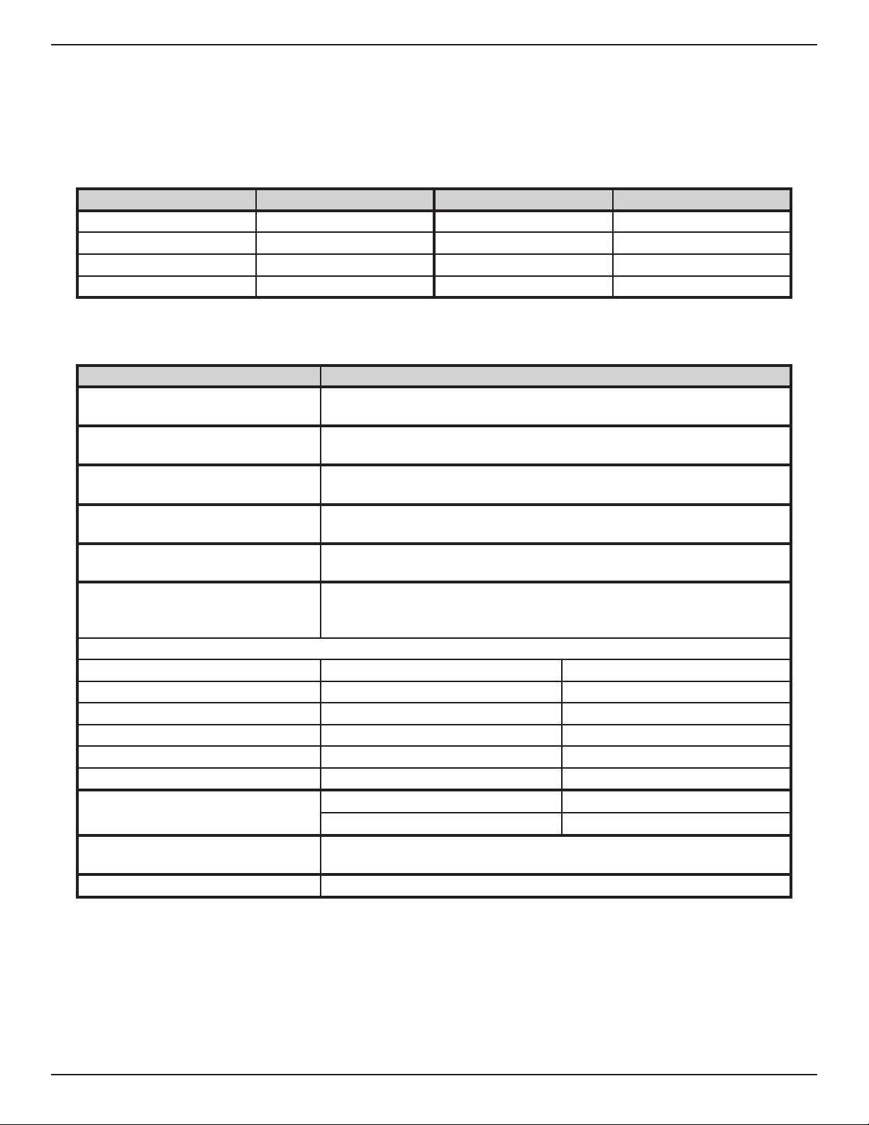
Issue Explanation Solution
LED’s cycling slowly from right to
left.
The 212iLM Mullion is designed to
monitor for low voltage. Once low
voltage is detected, the keypad
turns off the backlighting to ensure
operation of the keypad until the
problem can be attended to.
Verify the power supply output
voltage. If it is below the voltage
threshold of 7.5 Volts AC or 9 Volts
DC, you must increase the voltage
to between 12-24 Volts.
LED’s cycling rapidly from left to
right and the keypad has lost all
operation.
The 212iLM Mullion is designed
to monitor for over voltage. This
is a very “severe” condition and
significantly affects the keypad’s
operation. Once the over voltage is
detected, the keypad shuts down all
operation and does not operate until
the voltage is lowered.
Verify the power supply output
voltage. If it is over the voltage
threshold of 35 Volts, you must
lower the voltage below 29 Volts.
Can’t access programming mode
using the master code.
The code you are entering is likely
not the master code.
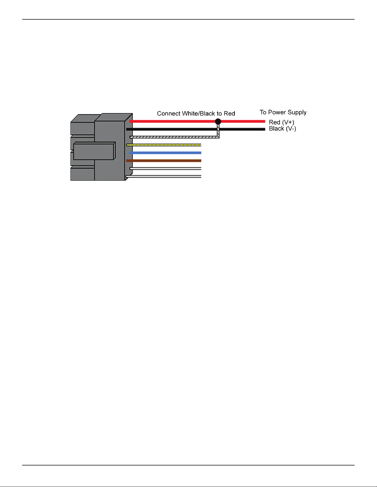
Perform the program mode
loopback in the following section to
enter program mode and reprogram
the master code.
No LED’s are lit on the keypad. Power is not reaching the keypad. First verify there is voltage at
the keypad. If not, verify there is
voltage at the power supply. If
there is voltage, verify continuity
on the wires out to the keypad.
Otherwise contact the power supply
manufacturer or Nortek Security &
Control if there is a problem with the
keypad. You also may try power the
keypad with a 12V battery to verify
operation.
DEALERS/INSTALLERS ONLY! End users must contact the dealer/installer for support. If the keypad still does not
work after troubleshooting, please call the Technical Services department at 1-800-421-1587.
Testing the Keypad
After installing the keypad, it is recommended that you perform the keypad self-test once a year, to ensure that the keypad
is working properly.
●To perform the self-test, with the unit powered up, press the following keys on the keypad: 7890 # 123456 ✱
●If all 12 key presses are accepted, the keypad enters self-test mode.
●The LEDs alternate three times followed by the sounder beeping three times.

6-051344 X2 9
212iLM Keypad Installation & Programming
Program Mode Loopback
If you’ve forgotten the local program code use the following loopback connection to enter program mode. Power down
the unit, short the wires in the configuration illustrated, then power the unit back up. The yellow LED should be flashing.
Now change your local program code or reset the unit. Power the keypad down and reconnected the wire harness in the
original configuration.

10 6-051344 X2
212iLM Keypad Installation & Programming
Limited Warranty
This Nortek Security & Control product is warranted against defects in material and workmanship for twenty four (24)
months. This warranty extends only to wholesale customers who buy direct from Nortek Security & Control or through
Nortek Security & Control’s normal distribution channels. Nortek Security & Control does not warrant this product to
consumers. Consumers should inquire from their selling dealer as to the nature of the dealer’s warranty, if any. There
are no obligations or liabilities on the part of Nortek Security & Control LLC for consequential damages arising
out of or in connection with use or performance of this product or other indirect damages with respect to loss of
property, revenue, or profit, or cost of removal, installation, or reinstallation. All implied warranties, including implied
warranties for merchantability and implied warranties for fitness, are valid only until the warranty expires. This Nortek
Security & Control LLC Warranty is in lieu of all other warranties express or implied.
All products returned for warranty service require a Return Authorization Number (RA#). Contact Returns at
1-855-546-3351 for an RA# and other important details.

6-051344 X2 11
212iLM Keypad Installation & Programming
PAGE LEFT BLANK INTENTIONALLY

12 6-051344 X2
212iLM Keypad Installation & Programming
212ilM Mounting Template
Copyright ©2015 Nortek Security & Control LLC
Table of contents
Other Nortek Keypad manuals