manuals.online logo
Brands
  1. Home
  2. •
  3. Brands
  4. •
  5. North Star
  6. •
  7. Paint Sprayer
  8. •
  9. North Star 2820 User manual

North Star 2820 User manual

16 GALLON
EXTENDED BOOM KIT
ITEM # 2820
M2820E.1
OWNER’S MANUAL
00989
Any Questions, Comments or Problems
Call NorthStar Product Support 1-800-270-0810
Hours: Monday - Friday 7:00 AM to 5:00 PM CST
Saturday 7:30 AM to 11:30 AM
THANK YOU
2
Thank you for purchasing the North Star, 15 Gallon Extended Boom Kit. This boom kit is designed for long life,
dependability, and the top performance you demand. Please take time now to read through this manual so you can better
understand the machine’s operation, maintenance and safety precautions. Everyone who operates this sprayer with this
boom kit must read and understand this manual. The time you take now will prolong your sprayer’s life and prepare you
for it’s safe operation. Enjoy the exceptional performance of your North Star 15 Gallon Extended Boom Kit.
NOTICE
Northern Tool + Equipment Co., Inc. reserves the right to make improvements in design and/or
changes in specifications at any time without incurring any obligation to install them on units
previously sold.
This symbol means CAUTION, WARNING, or
DANGER. Pay particular attention to this symbol
throughout the manual. Failure to comply with these
instructions may result in personal injury or product
damage.
TABLE OF CONTENTS
THANK YOU 2
NOTICE 2
PARTS LIST 3
ASSEMBLY INSTRUCTIONS 3
SAFETY INSTRUCTIONS 6
CHEMICAL SAFETY 7
OPERATION INSTRUCTIONS 8
BOOM CALIBRATION 9
STORAGE INSTRUCTIONS 10
TROUBLESHOOTING 10
WARRANTY INFORMATION 11
PART LIST - 2820
3
47.5” Extended
Boom Arm
Qty - 2
35” Hose
Qty - 2
11.5” Hose
Qty - 1
21.5” Hose
Qty - 1
Small Hose Clamp
Qty - 8
Flat Seat Hose Barb
Qty - 2
Rubber Washer
Qty - 2
Female Garden
Hose Swivel
Qty - 2
11/16” x 3/8”
Tee Hose Barb
Qty - 2
Nozzle Nut
Qty - 4
#1.5 Spray Nozzle
Qty - 4
Nozzle Strainer
Qty - 4
Swivel Nut
Qty –4
11/16” x 3/8”
Elbow Hose Barb
Qty - 2
Boom Arm
Support
Qty - 2
ASSEMBLY INSTRUCTIONS
4
UNPACKING
1. Closely inspect all the contents of the carton.
2. If you have missing or damaged components:
Contact our Product Support department at 1-800-270-0810.
STEP 1: Disconnect the two FEMALE
GARDEN HOSE CONNECTORS from
the 3-WAY VALVE. Disassemble the
existing boom arms by removing the (2)
5/16 x 1” hex bolts, (2) 5/16 nyloc nuts,
and (4) 5/16” flat washers as shown.
Do not discard these fasteners, you will
need them in step 5.
00984
STEP 2: Assemble the 11.5” and 21.5” HOSE ASSEMBLY. Insert the FLAT SEAT HOSE
BARB into the FEMALE GARDEN HOSE SWIVEL. Insert the RUBBER WASHER into the
FEMALE GARDEN HOSE SWIVEL. Slide one SMALL HOSE CLAMP over one end of the
11.5” HOSE and insert FLAT SEAT HOSE BARB into one end of the hose and tighten the
clamp. Repeat this step with the 21.5” HOSE.
00985
ASSEMBLY INSTRUCTIONS CONTINUED
5
STEP 3: Insert the elbow hose barb
into the boom arm as shown.
Fasten to the boom arm using the
nozzle nut. Insert the nozzle strainer
into the hose barb. Place the nozzle
on top of the strainer. Be sure that
the opening on the nozzle is
positioned so that when the unit is
assembled, the opening points at the
ground. Tighten the nozzle and
nozzle strainer into the hose barb
using the swivel nut. Insert the “T”
hose barb into the holes in the boom
arm and the boom arm support as
shown. Install the nozzle nut, nozzle
strainer, nozzle and swivel nut.
Make sure that both nozzles point in
the same direction. Repeat this step
for the other boom arm switching the
direction of the nozzles so it doesn’t
point to the ground.
STEP 4: Assemble the 35” HOSE to the BOOM ARM ASSEMBLY. Slide a SMALL HOSE
CLAMP on each end of the 35” HOSE. Push the 35” HOSE on one of the hose barbs of the
BOOM ARM ASSEMBLY, tighten the SMALL HOSE CLAMP. Push the other end of the 35”
HOSE onto the other hose barb of the BOOM ARM ASSEMBLY, tighten the SMALL HOSE
CLAMP. Repeat this step with the other BOOM ARM ASSEMBLY.
00986
11/16” x 3/8” Hose Barb Elbow
11/16” x 3/8” “T” Hose Barb
Boom Arm Support
Boom Arm
Nozzle Nut
Nozzle Strainer
Nozzle
11/16” Swivel Nut
02367
ASSEMBLY INSTRUCTIONS CONTINUED
6
STEP 5: Attach BOOM ARM ASSEMBLY to BOOM BRACKET with existing (2) 5/16 x 1” hex
bolts, (2) 5/16 nyloc nuts, and (4) 5/16” flat washers as shown. Tighten the nuts until the arms will
hold their position but still pivot freely. Be sure to direct all nozzles downward.
STEP 6: Connect the 11.5” and 21.5” HOSE ASSEMBLIES assembled in step 2 to the BOOM
ARM ASSEMBLIES. Slide a SMALL HOSE CLAMP on the 11.5” HOSE ASSEMBLY then push
the hose onto the hose barb of the right BOOM ARM ASSEMBLY, tighten the SMALL HOSE
CLAMP. Thread the FEMALE GARDEN HOSE SWIVEL onto the 3-WAY VALVE. Repeat this
step with the 21.5” HOSE ASSEMBLY and the left BOOM ARM ASSEMBLY.
SAFETY INSTRUCTIONS
7
1. Never spray flammable liquids.
2. Never use an undersized discharge
nozzle.
3. Never operate the unit with broken or
missing parts.
4. Always wear safety glasses or goggles
and appropriate clothing when filling the
tank with chemicals.
5. Always follow the chemical
manufacturer’s recommendations when
using chemicals with this sprayer.
6. Always spray on calm days. Wind can
cause the sprayed chemicals to drift into
areas not intended for the spray.
7. Always use water that is clear and free
from debris.
8. Always Protect the sprayer from freeze
damage during storage.
9. Never point the spray gun at people or
animals, the sprayed chemical can be very
dangerous.
10. Never leave the spray gun unattended
while the unit has power to it.
11. Always flush the sprayer immediately
after use, especially before storing for
extended periods. Storing with chemical
residue will slowly degrade all parts in the
system.
12. Always wear eye protection when
spraying chemicals.
13. Always seek emergency medical care
immediately if: any chemical penetrates
your skin.
14. Never use the unit when under the
influence of drugs, alcohol or medication.
15. Never use the sprayer for anything
other than it’s intended use
16. Never attempt to clean nozzles when
there is power to the sprayer
17. Always follow all other guidelines and
safety instructions described in this manual.
18. Always tow the sprayer on flat or level
ground. If absolutely necessary, traverse
slopes up and down only!. Never tow the
sprayer sideways across a slope, you may
tip the sprayer or the tow vehicle.
CHEMICAL INSTRUCTIONS
8
1. Pay strict attention to all labels on the chemicals you are using.
2. Measure all chemicals carefully and follow all directions exactly.
3. Emulsion-type liquid sprays can be added directly to the tank.
4. Mix wettable powder herbicides properly. Be sure to allow for the proper concentration
as stated in the directions for the chemical you are using.
a. Pre-mix herbicide, with water, in a pail
b. Fill the tank half way with water.
c. Pour the premixed herbicide slowly in to the tank.
d. Finish filling the tank to the desired height and begin spraying.
* Don’t leave powdered chemicals in the tank over night, or vigorous mixing will be
required to remix the solution.
* Wash all body parts, clothing, and other materials that may have come in contact with
any chemicals.
* Clean the sprayer with the chemical manufacturer’s recommended cleaning agent.
Proper care of the sprayer will prepare the machine for safe operation and prolong it’s
useful life.
OPERATION INSTRUCTIONS
9
Before operating the sprayer, thoroughly read all safety and operation instructions.
TESTING FOR LEAKS
Before operating the sprayer with chemicals, read all of the chemical safety instructions
and test for leaks.
1. Fill the tank with water.
2. Close the boom valves.
3. Turn on the pump with the remote switch. The pump is an “on-demand”
pump. This means when turned on the pump will pump until a preset
pressure is reached (60 psi) then it will shut itself off. When the boom valves
are opened or a gun trigger is squeezed the pump will automatically start
again...unless the remote switch is turned OFF.
4. Run the Boom as instructed in the BOOM OPERATION section. Run the
gun as instructed in the GUN OPERATION section.
GUN OPERATION
1. Turn both boom valves to the OFF position.
2. Turn on the sprayer.
3. Squeeze the gun trigger to turn on the pump and begin spraying.
BOOM OPERATION
1. Make sure the gun trigger is not locked open.
2. Open the boom valves as desired.
3. Unfold one or both of the boom arms as necessary for use of the desired nozzle.
4. Make sure both boom nozzles are directed towards the ground.
OFF
OFF
ON
ON
BOOM VALVES
BOOM VALVES
00602
5. The height of the unfolded boom nozzles should be about 23” from the ground.
The sprayer must be level with the ground to get this height. This will give the
correct double overlap spray pattern between the four nozzles. However, 1/5 of the
spray pattern must be overlapped each pass to get equal coverage throughout the
spray area.
0099
Use the tables on the next page to determine what speed to tow the sprayer at for the
desired application rate.
BOOM CALIBRATION
10
Below are some guidelines to calibrate a North Star boom sprayer with DT1.5 (253421) spray nozzles. This is a very
important step in operating the boom sprayer so the right amount of chemical is applied.
1. Use the suggested application rate from the chemical manufacturer (i.e. gallons per Acre, 1000 sq.ft., or 100 sq.ft.)
2. Using Table 1, find the application rate that most closely matches the chemical manufacturers suggested application
rate, and pressure at which the sprayer is operating.
3. Follow this application rate up the chart to find the speed at which to drive the vehicle.
TABLE 1
Spray
Pressure
Flow
GALLONS PER ACRE - Based on water
Height
Tip #
(PSI)
(GPM)
1 MPH
2 MPH
3 MPH
4 MPH
5 MPH
7 MPH
10 MPH
23”
1.5
15
.18
29.7
14.9
9.9
7.4
5.9
4.2
3.0
23”
1.5
25
.24
39.6
19.8
13.2
9.9
7.9
5.7
4.0
23”
1.5
35
.28
46.2
23.1
15.4
11.6
9.2
6.7
4.6
Spray
Pressure
Flow
GALLONS PER 1000 SQ.FT. - Based on water
Height
Tip #
(PSI)
(GPM)
1 MPH
2 MPH
3 MPH
4 MPH
5 MPH
7 MPH
10 MPH
23”
1.5
15
.18
.68
.34
.23
.17
.14
.10
.07
23”
1.5
25
.24
.91
.46
.30
.23
.18
.13
.09
23”
1.5
35
.28
1.06
.53
.35
.27
.21
.15
.11
Spray
Pressure
Flow
GALLONS PER 100 SQ.FT. - Based on water
Height
Tip #
(PSI)
(GPM)
1 MPH
2 MPH
3 MPH
4 MPH
5 MPH
7 MPH
10 MPH
23”
1.5
15
.18
.068
.034
.023
.017
.014
.010
.007
23”
1.5
25
.24
.091
.046
.030
.023
.018
.013
.009
23”
1.5
35
.28
.106
.053
.035
.027
.021
.015
.011
* Approximate flow from one nozzle
4. Use Table 2 to choose the throttle setting on the vehicle.
TABLE 2
5. The coverage area can be found by dividing a full tank (ie; 15 gals) by the application rate.
Example: 15 gallons divided by 30 gallons/acre = 1/2 acre of coverage per tank.
Speed
Time required in seconds to travel a distance of:
(MPH)
100 ft.
200 ft.
300 ft.
1
68
136
205
2
34
68
102
3
23
45
68
4
17
34
51
5
14
28
41
7
9.5
19
29
10
7
14
20
STORAGE
11
Prepare the sprayer for storage by running a permanent type of antifreeze through
the system. This will keep internal parts lubricated, protect against corrosion, and
keep the unit from freezing.
FOLLOW THESE STEPS
1. Pour about 1/2 gallon of regular antifreeze and 1/2 gallon of water, or 1 gallon of
RV antifreeze (do not dilute) into the tank.
2. Turn on the pump motor, place containers under the nozzles to capture the
antifreeze when it comes out. Open boom valves briefly until antifreeze begins to
exit the nozzles. Squeeze the gun trigger briefly until fluid begins to exit.
When removing: from storage drain the antifreeze left in the tank into a container.
Fill the tank with fresh water and run through the system, opening boom lines until
the system is completely flushed. Be sure to set up containers to capture the
expelled fluid if necessary.
Important
Most standard antifreeze is hazardous to people, animals and the environment.
Follow the containment and disposal instructions for your particular type of
antifreeze.
TROUBLESHOOTING
Problem
Possible Cause
Solution
Pump will not turn on.
Bad electrical connection.
Check all connections and
check condition of wires.
Pump cycling (turning on and
off repeatedly)
Clogged nozzles / strainer,
Clogged Discharge hose.
Clear nozzle / strainer, hose
Remove obstructions.
Low pressure
Worn nozzles
Replace nozzles.
Low flow
Clogged intake
Remove obstructions.
Poor spray distribution
Worn nozzles,
Clogged nozzle / strainer.
Replace nozzles
Clear nozzle / strainer.
WARRANTY REGISTRATION INFORMATION
12
Take time now to fill out your warranty registration card included with this product. It is extremely
important that you return the registration card. Furthermore, your comments and suggestions on the
warranty card or the survey card are very valuable to us, and help us to design better products.
Your Customer #
Your Customer # is on your invoice if you bought this unit through mail order. If you purchased this unit
in a retail store, write in the city where the store is located.
NorthStar Serial #
The NorthStar Serial # is printed on the silver North Star label, usually placed on the pump motor. It
consists of two numbers. Write down both numbers on the line.
Engine Serial # (If applicable)
The Engine Serial # is usually located on the side of the engine near the oil fill cap. See the component
identification section in the engine owners manual.
Pump Serial #
For the Pump Serial # write down the pump model number written on the pump label
Any Questions, Comments or Problems
Call NorthStar Product Support 1-800-270-0810
Hours: Monday - Friday 7:00 AM to 5:00 PM CST
Saturday 7:30 AM to 11:30 AM

Other North Star Paint Sprayer manuals

North Star M282737F User manual

North Star

North Star M282737F User manual

North Star 999883 User manual

North Star

North Star 999883 User manual

North Star M282727K User manual

North Star

North Star M282727K User manual

North Star M268180M User manual

North Star

North Star M268180M User manual

North Star 282805 User manual

North Star

North Star 282805 User manual

North Star 2681022 User manual

North Star

North Star 2681022 User manual

North Star 2851701 User manual

North Star

North Star 2851701 User manual

North Star M2827271A User manual

North Star

North Star M2827271A User manual

North Star 282795 User manual

North Star

North Star 282795 User manual

North Star MTBSL User manual

North Star

North Star MTBSL User manual

North Star M2681791A User manual

North Star

North Star M2681791A User manual

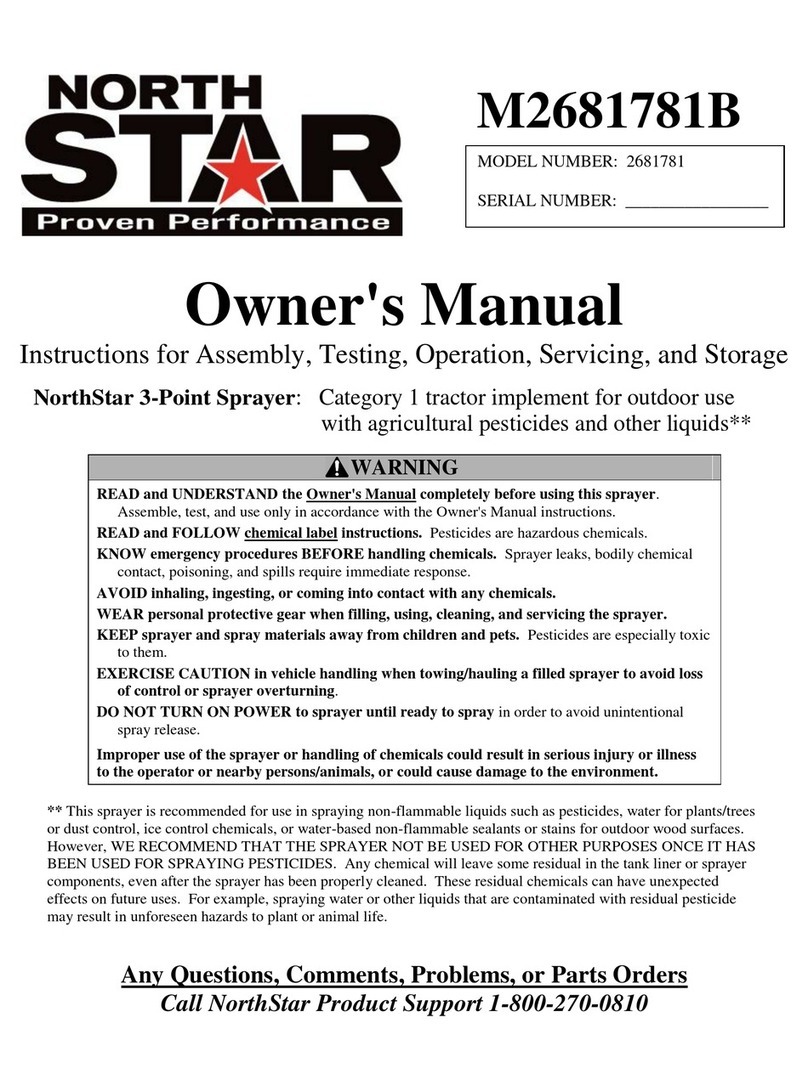
North Star M2681781B User manual

North Star

North Star M2681781B User manual

North Star 5042373 User manual

North Star

North Star 5042373 User manual

Popular Paint Sprayer manuals by other brands

Craftsman CMXCAFG190643 instruction manual

Craftsman

Craftsman CMXCAFG190643 instruction manual

ATD AIR ATD-6900A instruction manual

ATD AIR

ATD AIR ATD-6900A instruction manual

Chapin 63863 use and care manual

Chapin

Chapin 63863 use and care manual

Case IH 3230 installation manual

Case IH

Case IH 3230 installation manual

SAMES KREMLIN Nanogun Airmix H2O user manual

SAMES KREMLIN

SAMES KREMLIN Nanogun Airmix H2O user manual

Newstripe RollMaster 5000 product manual

Newstripe

Newstripe RollMaster 5000 product manual

Apollo Happy-Mist instruction manual

Apollo

Apollo Happy-Mist instruction manual

WAGNER GM 5000EA Translation of the original operating manual

WAGNER

WAGNER GM 5000EA Translation of the original operating manual

DaytonAudio PUCK TT25-8 user manual

DaytonAudio

DaytonAudio PUCK TT25-8 user manual

Archon RTB16 Installation, operation, &  maintenance instruction

Archon

Archon RTB16 Installation, operation, & maintenance instruction

Graco 240539 quick start guide

Graco

Graco 240539 quick start guide

Smith Performance Sprayers Industrial & Contractor Series use and care manual

Smith Performance Sprayers

Smith Performance Sprayers Industrial & Contractor Series use and care manual

Graco Xtreme 309329 Operation manual

Graco

Graco Xtreme 309329 Operation manual

PBM HAV Series Owner's/operator's manual

PBM

PBM HAV Series Owner's/operator's manual

Tornador Z-010S instruction manual

Tornador

Tornador Z-010S instruction manual

Hozelock 4122 instructions

Hozelock

Hozelock 4122 instructions

Birchmeier REC 15 ABZ Instructions for use

Birchmeier

Birchmeier REC 15 ABZ Instructions for use

Goldacres Compact 300L Operator's & parts manual

Goldacres

Goldacres Compact 300L Operator's & parts manual

manuals.online logo
manuals.online logoBrands
  • About & Mission
  • Contact us
  • Privacy Policy
  • Terms and Conditions

Copyright 2025 Manuals.Online. All Rights Reserved.