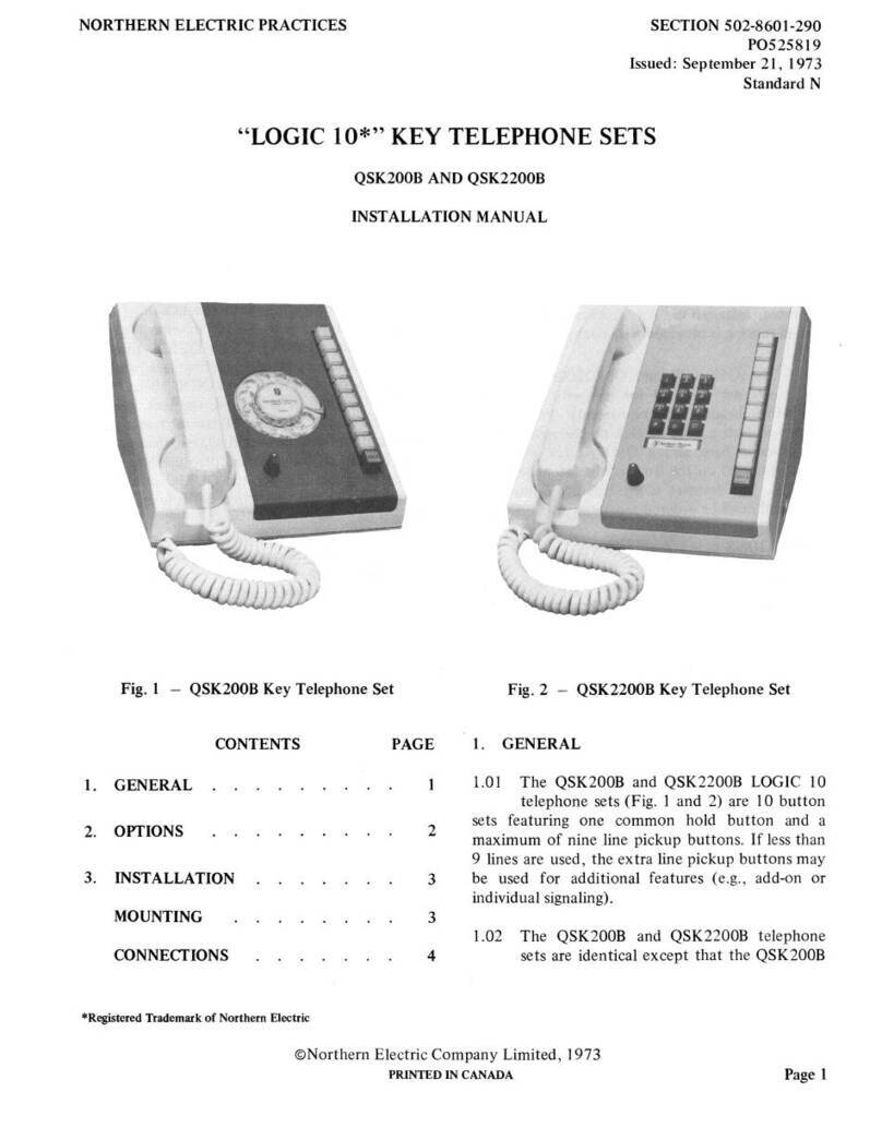
NORTHERN ELECTRIC NE-500 Instruction Manual

NORTHERN ELECTRIC PRACTICES SECTION 502-5101-201
Issued:
30
November 1973
Standard
I.
2.
3.
4.
5.
TELEPHONE SETS
NE-500, NE-1500 (MD), NE-2500
NONBUTTON AND ONE-BUTTON TYPE
IDENTIFICATION, INSTALLATION, AND MAINTENANCE
CONTENTS PAGE CONTENTS (Co
nt)
PAGE
GENERAL 789
C.
Turnbutton
/Pus
hbutton
813
D. Ringer Capacitor 815
DESCRIPTION 790 6. ASSEMBLY
OF
PARTS 815
GENERAL 790 A. Housing (Desk Telephones) 816
COMPONENTS 793
B.
Housing (Wall Telephones) 816
C. Ringe
rs
816
A. Mounting Cord 793 D. Dial 816
B. Handset 793 E. Apparatus Blank (Desk Telephones) 817
C.
Rotary
Dial (NE-500
Type)
793
F.
Apparatus Blank
(Wall
Telephones) 817
D. DIGITONE* Dial (NE-2500
Type)
793 G. Cords (Handset and Mounting) 818
E. Line Switch 793 H. Line Switch Cover Assembly 818
F. Ringer 793 I. Exclusion Switch 818
G. Network 795 J. Plunger 818
K. Turn
button
and Terminal Strip 819
ORDERING INFORMATION 795
L.
Faceplate
(N
E-2500 Type
Telephone) 819
FEATURES 795 M. Designation Window (NE-2
500
Type Telephon
e)
819
IDENTIFICATION 795 1. GENERAL
GENERAL 795 1.01 This section co
nt
ains information for
th
e
TELEPHONE SET IDENTIFICATION 795 identification, installati
on,
and maintenance
of
no
nbutton
and one-button NE-500, NE-1
500
INSTALLATION 808 (
MD
), and NE-2500
type
wall and desk telephone
sets.
MAINTENANCE 808
1.
02
The
NE-1
500
and NE-1554
typ
e telephone
A. Line Switch Assembly 813
se
ts are manufac
tur
e discontinued
(M
D) and
B. Exclusion
or
Monitor Switch 813 are superseded
by
th
e NE-2500 and NE-2554 type
•A
tudemuk
of Northern Electric.
©Northern Elec
tr
ic Compa
ny
Limited, 1973
PRINTED
IN
CANADA
789

SECTION 502-5101-201
telephone sets. The components
of
the NE-1500
(MD) type telephone sets are compatible with the
NE-2500 type telephone sets except for the dial
and housing.
1.03
An
NE-426A electron tube (Fig. 3) or a
P0895087 ringer isolator kit (Fig.
4)
may be
installed within the telephone set to correct
inductive noise conditions. Refer
to
the section on
the P0895087 ringer isolator kit for connection
information.
2. DESCRJYI'ION
GENERAL
2.01 The NE-500 and NE-554
type
telephone
sets are equipped with a rotary dial. The
dial may be replaced
in
the field, with an NE-95B
apparatus blank,
if
the telephone set
iS.
converted
for manual operation. (Fig. 5 and 6.)
Fig. 1 - NE-25000 Telephone Set
790

SECTION 502-5101-201
+EXCLUSION
SWITCH
NE-584
TYPE
C:.WJ+--
2 LINE &
SIGNAL
SW
ITCH
Fig. 2 - NE-2558DR Telephone Set
791

SECTION 502-5101
-201
792
•
-
Fig. 3 -
N&500
Type Telephone
Set
Showing Method
of
Mounting NE-426A Electron Tube
Fig. 4 - NE-500 Type Telephone
Set
Showing Method
of
Mounting P089S087 Ringer Isolator

2.02
The
NE-1500 (MD) and NE-1554 (MD)
type telephone sets are identical to the
NE-500 and NE-554 type except they are equipped
with a IO-button NE-25 type DIGITONE dial.
2.03
The
NE-2500 and NE-2554 type telephone
sets are similar
to
the NE-500 and NE-554
except they are equipped with
an
NE-35 type
DIGITONE
dial
COMPONENTS
2.04 All components (except the line switch
plungers on the desk type telephone sets)
are mounted on the base
of
the set.
Th
e line switch
plungers are part
of
the housing assembly.
A.
Mounting Cord
2.05 NE-500, NE-1500 and NE-2500 desk type
telephone sets are provided with a
5-
1/2
foot mounting cord, which may be replaced with a
9-
or
13-foot
NE-D
type 3-conductor cord,
or
a
13-foot
NE-D
type 4-,
6-
,
10-
or
16-
conductor
cord.
The
mounting cord is connected
to
the
service leads through the appropriate connecting
block.
B.
Handset
2.06 All sets are shipped with an
NE-G
3AR
handset. The handset may be replaced with
a handset containing an amplifier, such as the
NE-G6AQ
IA
for customers with impaired hearing,
or
an NE-G7AQ1A for customers with impaired
speech. An NE-GSAQIA handset may
be
used
in
noisy locations.
C.
Rotary Dial (NE-5,
00
Type Sets)
2.07 Most NE-500 type telephone sets are.
equipped with QDB I type dial
s.
Th
e NE-7
(MD) type dial is superseded
by
th
e
QDB
I type
dial.
The
rotary dial is available with or without
the word "OPERATOR" printed on the number
plate and must be specified when ordering.
SECTION 502-5101-201
D. µIGITONE Dial (NE-2500 Type Sets)
2.08 NE-2500 type DIGITONE sets are equipped
with NE-35Q3A1 12-button dia
ls
.
The
NE-25 type 10-button dial and NE-35 type
12-button dial are
MD
and are superseded
by
the
NE-35Q type dial. The wiring connections for the
NE-35Q type dial diff
er
from the NE-25 type and
NE-35 type dials and circuit modifications must
be
perfotmed as detailed
in
the appropriate section.
Th
e two additional buttons
on
the NE-35Q type
dial are designated * and
t:l.
While operational,
their use is restricted
to
end-to-end signaling.
The
DIGITONE dial is available with
or
without the
word "OPERATOR" printed on the "O" button,
and must be ordered accordingly.
2.09
The
NE-35Q type dial assembly contains a
line-powered oscillator, which generates two
frequencies when a
button
is depressed. These
frequencies are transmitted
to
the
CO
, which must
be equipped with a converter. The converter
accepts
th
e oscillator signals and translates them
into a 2-out-
of
-5
code for crossbar offices,
or
dial
pulses for step-by-step offices.
E.
Line Switch
2.
10
The card-operated line switch uses
bifurcated contact springs
to
improve
reliability.
The
se are protected by a plastic cover.
Th
e
lin
e switch is held in
th
e off-hook position by
a coil spring.
The
weight
of
the NE-G3AR handset
is suffici
ent
to
overcome the force
of
the coil
spring
,-
allowing the card
to
return the line switch
contacts to the on-hook position.
F. Ringer
2.11 Most telephone sets are equipped with
NE-C4A ringers.
Th
e ringer volume may be
adjusted for four
lev
els using
th
e four
corresponding positions
of
the volume control,
(Fig. 7 and 8). A fifth position is supplied for
manual ringer cutoff. an installation option.
793

SECTION 502-5101-201
794
Fig. 5 NE-500
Type
Telephone Set Housing Equipped With an
NE-958 Apparatus Blank
LATCH
ASSEMBLY
NE-95
B
APPARATUS
BLANK
6-32
x
0.50
MACHINE
SCREW
6-20
x 0.
312
BTP
TYPE
SELF
TAPPING
SCREW
Fig. 6 - NE-554
Type
Telephone Set Housing Equipped With
an
NE-95B Apparatus Blank

G. Network
2.12 NE-500, NE-554, NE-2500, and NE-2554
type telephone sets are equipped with an
NE-425QE1 network, which contains the necessary
apparatus for automatic line equalization.
In
most
telephone sets a
ll
connections
to
the set are made
on the network terminals.
The
NE-425QEl
network provides five extra bridging terminals with
no electrical connection
to
the network circuits.
The
NE-425B (MD)
or
NE-425E (MD) networks
are superseded by the NE-425QE1 network.
Fig. 7 -NE-500 Type Telephone Set Base
Showing Date Stamp and Ringer
Vo
lume Control
ORDERING INFORMATION
2.13 When ordering the sets the desired color
must be specified, using the suffixes given
in
Table A (e.g.,
to
NE-500CR- add
03
to indicate
black).
FEATURES
2.14
The features
of
each telephone
se
t are
shown
in
Tables B, C, and D.
SECTION 502-5101-201
TABLE A
TELEPHONE SET COLOR CODES
COLOR OOLOR SUFFIX
Black -03
Ivory -50
Green
-51
Red -53
Yellow -56
White -58
Pink -59
Light Beige -60
Light Gray
-61
Blue -62
Turquoise -64
3. IDENTIFICATION
GENERAL
3.01 The code number and assembly date are
stamped on the base
of
each telephone set
(see Fig. 7). Double code numbers (e.g., NE-500
C/D or CR/DR) permit field conversion from
rotary dial to manual operation or vice versa,
without changing the code number stamped
on
the
base
of
the set.
Th
e letter R indicates that the
telephone set is equipped with a spring type
retractile handset cord.
The
R - marking has been
discontinued
on
telephone sets
of
recent
manufacture.
TELEPHONE SET IDENTIFICATION
3.02 NE-500DR. The NE-500DR telephone set is
the basic rotary dial single-line desk set.
The
set components include an NE-G3AR handset, a
QDB 1 type dial, and NE-425QE1 network, a
3-conductor mounting cord and an NE-C4 type
ringer with adjustable volume control. The
NE-500DR telephone set is shown in Fig. 9.
796

SECTION 502-5101-201
LINE
SWITCH
COVER
EARS
NE-425QE1
NETWORK
NE
-
G3AR
HANDSET
,._-
RINGER
VOLUME
CONTROL
Fig. 8 - NE-554BR Telephone Set With Housing Removed
796

SECTION 502-5101-201
Fig. 9 -
NE-SOODR
Telephone
Set
3.03 NE-500CR.
The
NE-SOOCR
telephone set is
'
identical
to
the
NE-SOODR
telephone set,
except the
rotary
dial
is
r
ep
laced with an NE-95B
apparatus blank and the
se
t is wired for use with
manual telephone systems.
3.04
NE-500DQJ
A.
The
NE-SOODQlA
telephone set
is
identical
to
the
NE-SOODR
telephone set, except
it
is equipped with a QDB 1C
all-number dial.
3.05 NE-500DQJB.
The
NE-SOODQIB telephone
set is identical
to
the
NE-SOODQ
IA
telephone set, except it has a grounding button.
3.06 NE-500QD.
The
NE-SOOQD
telephone set is
identical
to
the
NE-SOODR
t~lephone
set,
except it is equipped with an NE-C4Q3A ringer
which has no external volume control.
3.07
NE
-500FR.
The
NE-SOOFR
telephone set is
identical
to
the NE-
SOODR
telephone set,
except it is equipped with a modified line switch
and is wired
to
avoid
inter
ference
with
the dialing
or
talking
of
another subscriber
on
a multiparty
line. When the handset
is
lifted off-hook, a low-loss
receiver circuit
is
bridged across the line due to
partial operation
of
the line switch.
If
the line
is
not
busy, or
if
an incoming call
is
to
be answered,
the left plunger (Fig. 10)
is
pulled up fully
to
complete the operation
of
the line switch,
completing the talking and dialing circuit.
Replacing the handset restores
both
the line switch
and monitor switch
to
the unoperated position.
Fig. 10 -NE-SOOFR Telephone Set Housing
797


restore the excluued service to normal, the plunger
is restored
to
its normal position
or
the handset
is
placed on-hook. The NE-D6AA mounting cord
contains sufficient leads to permit connection
to
either NE-lAl or NE-1A2 KTS
or
the exclusion
circuit.
The
NE-5028R-6l telephone set is supplied
with an NE-D6AA-6l cord and can be modified for
use with data
se
ts.
3.22 NE-502AR. The NE-502AR telephone set is
identical
to
the NE-5028N telephone set,
except the dial
is
replaced with an NE-958
apparatus blank and the set is wired for
use
with
manual telephone systems.
3.23 NE-502QA. The NE-502QA telephone set
(Fig. 11) is identical to the NE-5028R
telephone set, except
it
is equipped with an
MD2993 pushbutton which, when depressed, may
be used for signaling.
3.24
NE-5/0BR.
The NE-5108R telephone set is
identical to the NE-500DR telephone set,
except
it
has two separate lines which are selected
by
a turnbutton-pushbutton. Depressing the
SECTION 502-5101-201
button provides momentary connection between
two contacts for signaling.
To
permit incoming-call
audible signaling on
both
lines, an external ringer
may be connected
to
the
second line. The
turnbutton can also serve as a transfer
or
cutoff
key on lines, line extensions, ringers, etc. The
features extend
to
the connecting block through
the NE-D6AA mounting cord, which is connected
to
the terminal strip within the telephone set.
3.25 NE-5/
0AR.
The NE-510AR telephone set
is
identical to the NE-5108R telephone set,
except the dial is replaced by an NE-958 apparatus
blank and the set
is
wired for use with manual
telephone systems.
3.26
NE
-51
OFR.
The
NE-51
OFR
telephone set is
identical to the NE-5108R telephone set,
except the NE-51
OFR
is equipped with a
lift-to-talk- and-dial plunger as described for the
NE-500FR telephone set. (See 3.07.)
3.
27
NE-51
OER.
The NE-
51
OER
telephone set is
identical
to
the
NE-5
IOFR telephone set,
except the rotary dial
is
replaced with an NE-
958
Fig.
11
-NE-502QA Telephone Set
799

SECTION 502-5101-201
apparatus blank and the set
is
wired for use with
manual telephone systems.
3.28 NE-5/0QA.
Th
e NE-5
lOQA
telephone set
is
identi
ca
l
to
the NE-51OFR telephone set,
except
it
is provided with an
MD
2993
pushbutton
which provid
es
th
e features described for the
NE-502QA telephone set. (See 3.23.)
3.29 NE-51J
DR
.
The
NE-511DR telephone set is
identical
to th
e NE-51
OBR
telephone set
(see 3.24), except
it
is equipped with an
exclusion-switch assembly which is activated
by
lifting the left line switch plunger.
The
NE-Dl 6QA
mounting cord extends the control leads from the
terminal strip and network
to
facilitate connection
to
the QUS1
type
hands-free unit, the NE-3 type
speakerphone,
NE-lAl
KTS, NE-1A2 KTS and
exclusion circuit
s.
The
NE-51
lDR
telephone set
may also be used with data sets.
3.30
NE
-51JCR.
Th
e NE-51
lCR
telephone set
is
identical
to th
e NE-51
lDR
telephone set,
except
the rotary dial is replaced with an NE-95B
apparatus blank and the set
is
wired
for
use with
manual telephone systems.
3.31 NE-5JJDQA.
The
NE-Sl lDQA telephone
set is identical
to
the NE
-5
1
lDR
telephone
set except
it
uses a QDB
ID
all-number dial.
3.32 NE-2500D.
The
NE-2500D telephone set is
identical
to
the
NE-SOODR
te
lephone set,
except
it
has a DIGITONE dial. All components,
except
the housing, faceplate, dial, and dial
bracket, are interchangeable between the
NE-SOOD
and
NE-25000
telephone sets.
The
NE-25000 is
shown in Fig. 1.
3.33
NE-2500MQA.
The
NE-2500MQA
telephone set
is
identical to the
NE-25000
telephone set, except for the NE-D4BJ
4-conduc
tor
cord which permits connection
to
either an
NE-lA
l
or
NE-1A2 KTS.
The
NE-2500MQA telephone set may be modified on
the terminal strip within the set
to
obtain audible
signaling
on
a separate pair
of
leads.
800
3.34
NE-2500SQA.
The
NE-2500SQA telephone
set
is
id
e
nti
cal
to
the NE-2500D telephone
set,
except
for additonal line
swi
tch contacts a
nd
a
l0-conductor NE-D l
OH
cord necessary for
con
ne
ction
to
the QUS l
type
hands-free unit, the
NE-3
type
speakerphone or
NE-lAl
, and NE-1A2
KTS.
3.35
NE-2500
YQA
.
The
NE-2500YQA
telephone set
is
identical to the NE-2500D
telephone set, except for the message-waiting lamp
on the face
of
the set.
Th
e features and their
operation are identical to those de
sc
ribed for the
NE-SOOYR
telephone set for rotary dial systems.
(See 3.14.)
3.36
NE
-25
/JDQA
.
Th
e NE-251JDQA
telephone set
is
similar
in
appearance to the
NE-2500D telephone ·set.
The
NE-251 lDQA
telephone set is
equ
ipped with an NE-584AQA key
(turnbutton-pus
hbutton)
and an exclusion
swi
tch
to
provide
th
e features as described for the
NE-511DR telephone set. (See 3.29.)
3.37 NE-554BR. The NE-554BR telephone set
is
a single-line wall telephone set. (Fig. 12.)
Th
e set components include an NE-63AR handset,
a QDB l type dial, an NE-425QE1 network, and an
NE-C4 type ringer with adjustable volume control.
3.38 NE-554AR.
Th
e NE-554AR telephone set
is
identi
ca
l
to
the NE-554BR telephone set,
except the dial is rep
la
ced with an NE-95B
apparatus blank, (Fig. 6), and the set
is
wired for
manual service.
3.39
NE
-593BRW.
The
NE-593BRW telephone
set is identical
to
the NE-554BR te
le
phone
set, except it is
not
equipped with a ringer.
3.40 NE-503ARW.
The
NE-593A
RW
telephone
set is identical
to
the NE-554BR telephone
set,
except
it is
not
equipped with eith
er
a ringer
or
a dial.
The
dial is replaced
by
an NE-95B apparatus
blank and the set
is
wired for manual service.

SECTION 502-5101-201
Fig.
12
-NE-554
Type
Wall Telephone Set
801

SECTION 502-Stol-201
3.41 NE-554QD. The NE-554QD telephone set
is
identical
to
the NE-554BR telephone set,
except it is not equipped with an external ringer
volume control.
3.42 NE-554FRN. The NE-554FRN telephone
set is ipentical to the NE-554BR telephone
set, except
it
is
equipped with a modified line
switch and is wired
to
avoid interference with the
dialing
or
talking
of
another subscriber on a party
line. When the handset is lifted, a low-loss receiver
circuit is bridged across the line due .
to
partial
operation
of
the line switch.
If
the line is
not
busy,
or
if
an incoming call
is
to
be
answered, pushing in
the monitor switch (located on the right side
of
the
set), fully operates the line switch, completing the
talking and dialing circuit. Replacing the handset
restores both the line switch and monitor switch.
3.43 NE-556FRN (MD). The NE-556FRN (MD)
telephone set
is
identical
to
the
NE-554FRN telephone set, except it has an
NE-426A electron tube, and is intended·for 4-party
selective and 8-party semiselective· (polarized
ringing line) service.
3.44 NE-554BQA. The 'NE-554BQA telephone
set is identical
to
the
NE-5~4BR
telephone
set, except
it
has a
QDB
1C·
~ll-number
dial, and a
P096C252 signal switch located below and
to
the
right
of
the dial. The signal · switch: leads
cire
·
connected
to
a P338886 terminal strip located
on
the dial bracket.
3.45 NE-55JBQJA. The NE-554BQ1A telephone
set is identical
to
the NE-554BR telephone
set, except it has a
QDB
1C all-number dial.
3.46 NE-55JQ4A. The. NE-554Q4A telephone
set is identical
to
the NE-554BR telephone
set, except it has a ground switch located below
and
to
the right
of
the dial. The ground·switch is
wired between tip and ground. Depressing the
switch button connects one side
of
the line
to
ground.
3.47 NE-558DR. The NE-558DR telephone
~tis
the standard 2-line set.
It
is equipped with
standard components, except the dial is a
QDB
lB
dial with an additional set
of
contacts, which mute
802
the dial pulses for use in speakerphone systems. In
addition, the NE-558DR telephone set is equipped
with an exclusion switch and an NE-584B
tumbutton-pushbutton. Holes are provided in the
baseplate for mounting an NE-659A transmitter
for use in home communication systems. The
exclusion · switch and turnbutton-pushbutton
· provide
th~
following services:
(a) The exclusion switch provides a means
of
disconnecting an extension station by raising
the plunger pr-0jecting through the top
of
the
housing.
The
·switch returns
to
normal when the
handset is
r~placed
.
·
(b)
In
·home communications systems, the
exclusion switch may be used to place the
CO
line on hold while using the intercom.
(c) The tumbutton-pushbutton provides a
means
of
transferring the talking circuit to
·either
of
two lines. This switch can also be used
to
cut
off
or
transfer lines, extension stations,
ringers, etc. Depressing the button momentarily
closes a pair
of
contacts
to
provide signaling.
3.48 NE-558CR. The
NE-5
58CR telephone set is
identical
to
the NE-558DR telephone set,
except the dial is replaced with an NE-95B
apparatus blank, and the set is wired for manual
service.
3.49 NE-558DQA. The NE-558DQA telephone
set
is
identical
to
the NE-558DR telephone
set, except
it
has a
QDB
'lD all-number dial.
3.50
NE-2554BQIA
-.
The NE-2554BQ1A
telephone set is the standard single-line
DIGITONE wall set.
It
is identical
to
the
NE-554BR telephone set, except it is equipped
with an NE-35Q3A
(MD)
or
NE
-35Q3Al
DIGITONE dial. Left and right dial-mounting
adapters are required
to
mount the dial.
3.
51
NE-2558DR. The NE-2558DR telephone
set is the standard 2-line DIGITONE wall ·
set, (Fig. 2).
It
is identical
to
the NE-558DR
telephone set except it is equipped with an
NE-35Q3G (MD)
or
NE-35Q3Al DIGITONE dial,
and a P096C204 2-line switch, which allows the A
lead
to
be switched when changing lines.

MA
N
UAL
NE-501C
R-
•
NE-501
F.R-•
NE-SO~AR
-
•
NF.
-
SO~A R
-•
NF.-5
1
0AR-
•
NF.
-SIOAR-•
NE
-5I
OAR-•
NF.-5
I
OAR-•
E-510AR-•
NF.-510ER-•
NF.-510F.
R-*
NF.-5
IOF.R-•
NE-510ER-*
NE-
51
ICR
-*
NF.-51
ICR-•
NE-51
ICR-*
NF.-51
ICR-•
NE
-
51
ICR-•
NE-51
IC
R-•
TABLEB
ONE-BUTTON
DESK
TELEPHONE
SET
FEATURES
(Double-Line or Additional Equipment)
TELEPHONE
SET
DI
AL
ELEC
.
ALL
TUBE
ROTARY
DIGITONE
NUMBER
4-PARTY
KEY
SPEAKER-
LIFT-TO-
C
ALLI
NG
SEL.
RIN
G
SYSTEMS
PHONE
TALK
NF.
-
501
DR-• v
NF.-501
FR
-• v v
NF.-SO~BR
-•
v
NF.-50~BR-
•
v
NF.-50~0A-
*
NF.-5
IOBR-
•
NF.-510BR-•
NF.-5
IOBR-•
NF.
-510BR-• .
NE-5
IOBR
-•
NF.-510FR-*
NF.-5
IOFR
-•
1
F.-5
IOFR-•
NF.-5
IOFR-
•
NF.-5
IOQA-*
NF.-5
11
DR-•
l\F.-~511
DOA·*
v v
NF.-5
11
DR-*
NF.-~511
DOA
·* v v
NE-51
1
DR
-*
NF
-~
511
DOA
-•
v v
NF.-511
DR·*
NF.
-
~511
DQA-
* v v
J'ff-5
11
DR-*
NE
-~
51
IDOA-*
v v
NF.-5
11
DR-*
NE-~511
DOA-
* v v
N
E-511
OQA-*
v v v
•
Wlwn
onkrini:
th~
tt·
k'
pho11~
s~t
th
,·
<ksir,·d
rn
lor
must
ht' speci
fied
using
th~
suffixes
in
T
ahle
A.
SECTION
502-5101-201
NUMBER
OF
LINES
SIGNALING
PICKED
UP
CIRCUIT
I
I
I
I
I
2
I v
I v
I
I
2 v
2
I v
I v
I
2 v
2 v
2 v
I v
I v
I v
I v
(Cont'd Next
P1ge)
803

SECTION 502-S101-201
LINE
RINCER
...;
...;
...;
.j
..;
.j
.j
.j
.j
..;
.j
.j
...;
,1
804
TABLES
ONE-BUITON
DESK TELEPHONE
SET
FEATURES
(Double-Line
or
Additional Equipment)
CUTOFF
BY
KEY
RINGER
OR
C
OM~IONOR
BUZZER RINGER
OR
EXTENS
I
ON
PRIVATE LINE EXCLUSION CUTOFF BUZZER
STATION
AUXILIARY
RINGER
OR
BUZZ
ER
BY
EXCL
. IN SET
OR
RI
NGE
R
RE
CE
IVER
...;
v
...;
..;
,1
..;
...;
...;
../
.j
...;
.j
.j
.j
..;
...;
..;
.j
..;
.j
...;
.j
..;
...;
QBBIA
CONN.
GROUND
BLK
. BUlTON
...;
...;
..;

(I)
0
01
TE
LE
Pll
ON
E
SE
l
coot
ROTARY
OI
GIT
ON
E
MANUAL
NE
-S
OODR
-• l\E
-2S
OOD
-'
l\
l
-S
OOCR
·"
NE-
S
OODQ
IA·'
NE-500
DQ
IB·•
NE
-S
OO
F
R-•
N1
;.
soor
R-•
NE-S
OOFR
N·
"
N
E-
S
OO
MR
·'
Nl!
-
~ S
OO
M OA
·
'
Nli·S
OOL
K·'
N
E-
S
OOQ[).
•
Nf.
-
SOO
SR
-•
NF
-
2S
OOSOA
·'
NF
-
IOO
RR
_.
NE-SOO
YR
··
NF
-
~
soo
vo
,
v
N
l:·S
OO
WR
·'
NE·S
OOYQ
IA·'
NE-
S
OO
Y
QB·
'
N
f.
-S
OOPRN
·'
Nii
·S
OON
RN
-•
TABLE
C
NONBUTION
DE
SK
TEL
EPHO
NE
SET
FE
ATUR
ES
(Single-
lin
e)
OIA
I
LIFT
-TO-
TA
LK
\!AR
KI
NG
l\
U
'll.\
· F-'IGLISll
~
FY
SPf
:A
KER·
NU\IER
IC
NU
\tERIC
F.
NG
LISll
ANO
SYSTI::
\I
PllO'l
l'
FR
ENt1
1
"
"
" , 1 "
" ,1
" "
" ,I " v
"
"
" ,1
"
..;
• Whenorde
.r
i
ni;
the lr
kr
ho
nc
..ct
lh
l•
d,·,1r
1..
·
ll
"""
lor1
nu
..l l'
1,.'
'1"-'i.
•1
1i
:l
l
11
..
u
1
~
th
•'
..
uth\
"'
'
111
T.1hk
r\,
/\'
nt
t'J
'
\
ffS~Af.I
c;nou
'ln
WM
Tl
'IG
DU
IT
ON
"
,1
,, ,1
,1
I, Equ
iJ'l
i:it
d
,,.,.
ith
1't:
.(-
4Q
J,
\ ""'
"'
;anJ
no,·
,ttttt..il ,
,1Jt11•1i:
''''11r·•l
~
r.1r
ll
o•t,•J
"-' \
.,I.,
C\
\",
l
1,.'P
1
11"-'"'
"
;•'•'.l..;.llllTC.:
LJ111,
,t •
'lt
ll
l(
l N
ot
equir
pt'd
""'
ith
;m
K1
r
irr
.a
1
..
1
:11n..,,J
..
,,,.
!'k'u"
1
...
1111'
1etr
t:"i:-.....rt'l··•••••·1r
.
ODnlA
CON
N.
RL
K
,1
"
v
,1
-
s1:e
NOT
E
I
4
~
.4
4
.1
3 a
0
z
"'
0
....
•
"'
-
0
-
~
-

GO
0
Gt
TELEPHO
NE
SET
DIAL
MAN
UA
L
ROTARY
DIGITONE
NE-SS4AR·
•
NE
-SS
48R·• NE·2SS4BQIA·•
NE-S93A
RW
-•
NE-S
93
BRW-•
NE
-SS
4
FRN
·•
NE-SS
4B
QA
·•
NE-SS4
BQ
IA
·•
NE-SS4Q4A·•
NE
·
SS8CR-
•
NE-SS8DR-•
NE-:?SS8DR
·•
NE-SS80QA·
•
NE-SS6FRN
.•
NE
-I
SS48-
•
NE
-SS
4QO
-•
TABLED
NONBUTTON
AND
ONE-BUTTON
WALL
TELEPHONE
SET
FEATURES
ELECTRON
ALL
TU
BE
NUMBER
NUMBER
..,,ARTY
LIFT
-
TO
·
TALK
OF
LI
NES
DIAL
SEL
.RlNC
PI
C
KED
UP
I
I
..;
I
..;
I
..;
I
I
~
..;
~
..;
..;
I
I
I
•
When
o
rdcrin
&t
he
telepho
ne
set
the
desired
color
must
be
s
pecified
using
the
suffixes
in
T
:1
bk:
A.
t No R
inge
r
volume
co
ntrol.
SIGNA
LI
NG
LINE
C
IR
CU
IT
RINGER
..;
..;
..;
..;
..;
..;
..;
..; ..;
..;
..;
t
GROUND
EXCLUSION
BlJTTON
..;
..;
..;
(/)
"'
~
0
2!
Vt
0
'I"
Vt
-
0
-
~
-

SECTION
S02-S101-201
0
~
n 0
[)
0 0
0
(Q)
( )
(Q)
0 0
0 0
D
l)
<=:) q
c::i © 0
0
Fo1
Fig. 13 -Present Production Baseplate
(Wall
Telephone)
t
I
-CENTRE LINE
OF'
BASE P
LATE
r:1
,
~
I
..
~
~,St
I IN. I"'-
l.
-
....:...L
-
--
-y-
1+ i..-:-17/
&IN
.
--l
• 35/
161N---j
I
Fig. 14 -Early Production Baseplate (Wall Telephone)
Showing Drilling Location for Mounting Holes
807

SECTION
502-51<
~
1-
20
1
4. INSTALLATION
4.
01
The
telephone sets shall be installed
according
to
the appropriate sections.
Connection information for each type
of
telephone
set is located
in
the section entitled,
TE
LEPHONE
SETS
-TYPE
CONNECTIONS.
4.02 Several
ho
les are provided in
th
e baseplate
of
the
wall telephone set
to
allow greater
flexibility in mounting and
to
minimize
the
use
of
a backboard (Fig.
13
). Baseplates
of
current
manufacture may be mounted on a conduit
outlet
box. Baseplates
of
ear
ly
production models require
modification.
4.03
To
modify early production baseplates, qrill
two holes as shown in Fig. 14 using a No.
17
(0
.173 inch) drill bit. If a conduit
outlet
box is
not
available,
mount
the telephone set with screw
anchors, using the mounting holes at the top and
bottom
of
the baseplate.
4.04
Refer to
th
e appropriate section for
information on screw anchors suitable for
mounting wall telephone
se
t
s.
4.05 When connecting a te
le
phone set
to
an
NE-IA, NE-IA1, NE-IA2,
or
NE-6A KTS, a
QUSl-type hands-free unit
or
an NE-3 type
speakerphone, refer
to th
e connection section on
the
particular telephone set being
in
stalled.
808
5. MAINTENANCE
5.01 Maintenance
of
the telephone sets consists
of
cleaning exterior surfaces, burnishing and
adjusting switch contacts, and. replacing defective
components.
5
.02
Housing, handset and dial pushbuttons can
be cleaned
wi
th
a soft cloth moistened with
water.
Do
1101
use scourl11g
powders
or
c/ea11ers.
Replace plastic components
if
cleaning does
not
have satisfactory results.
5.03 Check line and ground terminations, and
wire dressing before proceeding with
maintenance.
5.04
CO
station ringer and dial test circuits
should be used where possible when
checking telephone sets.
5.05 Network and line switch assemblies are
riveted
to
the baseplate.
Th
ese assemb
lie
s
are
not
normally replaced in the field, however,
they can be replaced by drilling
out
the rivet and·
using a No. 4 by 0.
250
(P097D700) self- tapping
screw.
5.
06
Chart 1
li
sts common troubles and their
probable causes, with suggested corrective
actions.
Other manuals for NE-500
1
This manual suits for next models
3
Table of contents
Other NORTHERN ELECTRIC Telephone manuals
