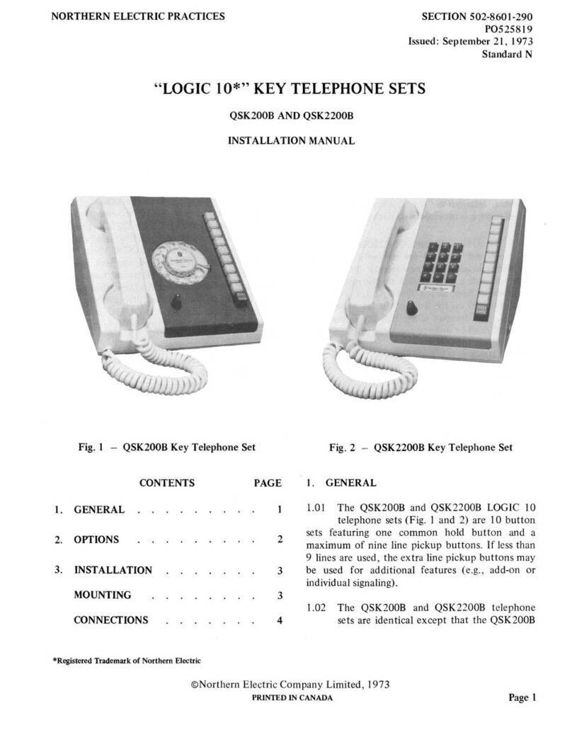
NORTHERN ELECTRIC QSD300A User manual

NORTHERN ELECTRIC PRACTICES SECTION 506-3211-200
Issued: 19 November 1973
Standard
PANEL COIN TELEPHONE SETS
QSD300A AND QSD2300A TYPES
PREPAY
IDENTIFICATION AND INSTALLATION
(a) QSD300A Type (b) QSD2300AType
Fig. 1 -
Front
View
of
QSD300A and QSD2300A Coin Telephone Sets
©Northern Electric Company Limited, 1973
PRINTED IN
CANADA
Page 1

SECTION 506-3211-200
CONTENTS PAGE
L GENERAL 2
2. DESCRIPTION 2
3. CIRCUIT DESCRIPTION 3
4.
ORDERING INFORMATION 4
5.
INSTALLATION 8
INSTALLATION REQUIREMENTS 8
MOUNTING INSTRUCTIONS 9
CONNECTIONS AND OPTION
SELECTION 10
6. OPERATION TESTS
22
1.
GENERAL
1.01 This section describes the QSD300A and
QSD2300A prepay, single coin slot, panel
coin telephone sets. Dismantling and assembling
information
is
given to facilitate installation
of
the
coin telephone sets. Station wiring and option
connections are also provided.
2. DESCRIPTION
2.01 The QSD300A and QSD2300A coin
telephone sets are single -slot, prepay type
panel coin tel.ephones. The QSD300A, equipped
with a rotary dial, and QSD2300A, equipped with
a DIGITONE* dial, are shown in Fig.
1.
The sets
can be converted from rotary dial
to
DIGITONE
dial by interchanging the door assembly.
2.02
The
panel coin telephone set components
are contained within a sheet steel housing
which is fabricated by a combination
of
welding
and bolt fasteners for maximum security.
*A trademark
of
Northern Electric.
Page2
2.03 The front
of
the set features a brushed
chrome center panel which contains the
coin slot, coin release lever, handset hook, dial,
instruction and number card windows, coin return,
and cash compartment door. Decorator panels
of
brushed stainless steel
or
. panels with a painted
finish are inserted on each side
of
the center panel.
2.04 The QSD300A and QSD2300A coin
telephone sets are equipped with
mechanical and electronic initial rate totalizers
which inhibit dialing from the coin telephone until
a preselected amount in coins has been deposited.
2.05 When shipped froin the factory, the
QSD300A and QSD2300A sets are arranged
to operate on the mechanical totalizer at a 10-cent
initial rate. With this arrangement the set may be
used on either ground-start
or
loop-start central
office (CO) lines.
2.06 The electronic variable initial rate (VIR)
totalizer on the printed circuit board (PCB)
assembly in the coin telephone set can be modified
to
change the initial rate from 5-cents
to
40-cents
inclusive in increments
of
5-cents.
2.07 The free access to selected numbers (FASN)
feature permits coinless calling to special ·
preselected numbers. The
CO
must be equipped for
FASN and the line must have a loop-start line
circuit.
2.08 Ground isolation (GI) disconnects the
grounding circuit from the transmission
path to minimize line induced noise during voice
transmission. This feature requires that the
CO
line
is equipped with a loop-start line circuit.
2.09 The coin identification signals are
transmitted to the operator by a solid state
tone generator when the required coins are
deposited in the coin telephone set.

'
2.10 The transmission qualities
of
the QSD300A
and QSD2300A coin telephone sets are
similar to those
of
the NE-500 type telephone set.
2.11 The maximum loop resistance for
satisfactory operation
of
the set
is
determined by such parameters as minimum CO
battery voltage, feeding-bridge resistance, ringing
cut-off current, etc. To ensure reliable operation
it
is recommended that the following conditions be
met.
(a) With the handset off-hook the de voltage
at
the ring and tip terminals
of
the set must
not
be l
ess
than 4.4 volts.
(b) The current in the ring side
of
the line
shou
ld
not
be less than 23.0 milliamperes
with the hopper trigger switch in the normal
position (i.e.,
not
tripped).
Example
of
long loop:
CO
battery
Feeding-Bridge
Resistance
Current
Loop resistance
45.0 volts
200 ohms X 200 ohms
23.0 millfumperes
1365 ohms
Note: Other factors associated with the
CO
SECTION 506-3211-200
coin switch module.
As
the coin passes through the
coin switch module, a switch is activated which
in
turn energizes the solid-state tone generator. The
generator sends bursts
of
tone appropriate
to
the
coin deposited
to
permit operatorrecognition. The
signals are
not
heard in the receiver
of
the coin
telephone set. The number
of
tone bursts for each
coin deposited are:
• one burst for a 5-cent coin
• two bursts for a 10-cent coin
•
five
bursts for a 25-cent coin (transmitted
at twice the.rate
of
the 5-cent and
10
-cent
coin tone bursts).
may limit the loop resistance to less than
23-l/
4
1365 ohms.
For
higher loop resistance a long
line circuit should be used.
2.12 The coin telephone set weighs
approximately
55
pounds (25 kilograms).
2.13 The dimensions
of
the QSD300A and
QSD2300A coin telephone sets are shown
in Fig. 2.
3. CIRCUIT DESCRIPTION
Coin Signaling
3.01 Coins inserted in the single slot and
accepted
by
the chute are sorted into the
appropriate channel before passing through the
'12-7/16
ALL
DIMENSIONS
SHOWN
ARE
IN
INCHES
Fig. 2 - Rear View ofQSD300A and
QSD2300ATelephone Sets,
Showing Physical Dimensions
Page
3

SECTION 506-3211-200
Mechanical Totalizer
3.
02
The
mechanical totalizer detects the total
number
of
5-cent coins deposited for
I0-cent initial rate calls.
3.03
The
first 5-c
ent
coin is trapped in the switch
module.
The
5-cent coin in the trapped
position holds a switch operated. This switch
provides a connection to ground which
is
necessary
for central offices having ground
start
line circuits.
The
second 5-cent coin
is
deflected by the first
5-cent coin (which is trapped) and passes
on
through the switch module i
nto
the coin relay
hopper.
On
entering the hopper,
it
trips the hopper
trigger switch.
The
operated hopper trigger switch
removes a
short
circuit from the dial and the user
can now dial.
3.04 A deposited 10-cent coin
or
25-cent coin is
segregated by the coin chute and passes
through the coin switch module.
The
tone
generator monitors the switches
on
the switch
module and generates the appropriate coin signals.
The
coin then drops into the coin hopper, tripping
the
hopper
trigger which allows the call to proceed.
The
mechanical totalizer is
not
operated by the
deposit
of
these coins.
ElectronicTotalizer (VIR)
3.05
The
electronic
tota
lizer
is
used to inhibit
dialing
(or
continuity
to
ground for FASN
operation) in the same manner as
the
mechanical
totalizer.
The
electronic totalizer receives its
input
signa
ls
from the same switches
on
the switch
module which provide inputs
to
the coin signal
tone generator.
The
electronic totalizer can be
strapped
(on
the PCB assembly) so
that
it enables
dialing
(or
continuity to ground for FASN
operation) when the total value
of
the coins
deposited equals
or
exceeds
the
preset initial rate.
The initial rate
may
be preset by appropriate
strapped connections
on
the PCB assembly.
FASN Operation
3.06 When the coin telephone
set
is used with a
CO which
is
equipped
to
psovide FASN
service the user receives dial tone
by
lifting the
Page 4
handset and may complete a call to any free access
number without depositing coins.
3.07 When a non-FASN call
is
made, ground
identification
is
detected· by the
CO
when
the initial rate
is
deposited.
GI Feature
3.08
The
GI feature provides a means
of
disconnecting the station ground from the
transmission network whenever line current is
flowing. This feature achieves a substantial
reduction in transmission circuit noise caused by
induced voltages on the line.
3.09 GI
is
activated by current
on
the ring side
of
the line. When this feature
is
used, ground
tests
or
coin collect/return functions, which
require an electrical continuity to ground, must be
made
on
the tip side
of
the line only.
Coin Rejection
3.10 Slugs, washers, tokens
or
foreign coins
inserted through the coin entry slot are
directed
to
the loin chute and rejected to the coin
return assembly
or
held up.
The
coin-return lever
when operated, has a positive clearing action,
which releases the slugs, washers, etc., into the coin
return assembly.
4. ORDERING INFORMATION
4.01
The
panel coin telephone sets are ordered as
follows:
COIN TELEPHONE SET QSD300A
COIN TELEPHONE SET QSD2300A
4.02
To
provide a complete installation the
following components must be ordered
separately.
• Cash compartment
doorNE-lA-30
• Cash compartment lock, NE-22QC
• Upper housing lock, NE-22QD (keys must
be ordered separately)

• Cash receptacle, NE-IB
• Cash receptacle cover, NE-IC
4.03 The QSD300A and QSD2300A are available
with the following decorator panels.
(a) Stainless steel decorator panels
P0502663
are supplied with all panel coin telephone
sets.
(b) Black decorator panels
P050266
2 are
available
but
have to be ordered separately.
(c) Zinc plated decorator panels
P050266
I are
supplied on a special order basis only (for
special paint finishes applied by the customer).
4.04 Instruction and number cards should be
supplied locally and must be in accordance
with the dimensions given in Table B.
4.05 The QSD300A and QSD2300A coin
telephone sets may be mounted
as
follows.
• Recessed into a wall so that the front panel
is
flush with the surface
of
the wall. The
Apparatus Box
QBM2A
(Fig. 3) is provided
to
fit into the wall prior
to
the installation
of
the coin telephone set. The customer
will be responsible for providing the recess
in the wall
of
the proper dimension
s.
Mounting screws are provided with the
Apparatus Box for the purpose
of
fastening
SECTION 506-3211-200
the coin telephone set to the Apparatus
Box. Dimensions and mounting screw holes
for the Apparatus Box are shown in Fig.
3.
See Table A for fasteners required.
• Mounted in a location where Burgess-Day
Type
101
Panel Coin Telephone mounted
in a Burgess-Day Type 1065-327 panel wall
mounting box
was
previously installed.
An
Adapter
QAA
l6A is available for this
purpose. Mounting screws are supplied with
this adapter.
• Mounted in furniture designed specifically
for this type
of
panel coin telephone.
4.06 The coin telephone set components that
may be substituted in the field are listed in
Table D.
4.07
If
the coin telephone set has been installed,
but
is
not
ready for service, place a QSWlA
out
of
service
sign
in the coin entry slot so that
customers cannot deposit coins. When service is
established, remove the
sign
or
arrange for the
agent
or
other responsible person
to
do so. The
QSW
IA sign, as shown in Fig. 4, is installed by
inserting the double pronged projection into the
coin entry slot and pressing firmly into place until
the
sign
is flush against the front surface. The
sign
may be removed
by
pulling
it
out
of
the coin entry
slot.
4.08 Installation accessories are listed in Table
C.
Page
5

SECTION
50
6-3211-200
TABLE A
FASTENERS USED IN MOUNTING APPARATUS BOX QBM2A
MOUNTING HOLE
SURFACES SIZE QUANTITY SIZE AND
TY
PE NOTES
REQUIRED
Softwood 1/8-inch
or
No. 30 8 1-3/4 inch No. 14 F.H. wood 1,2
screw
Hardwood 1/8-inch
or
No.
30
8
1-1
/4
inch No. 14 F.H. wood l,2
screw
Masonry Con- 5/16-inch 8 2-inch No. 14 F.H. wood 1,2
crete Brick screw in No.
16
plasticanchor
Cinder Block 3/4-inch 8 1/4 by 4-inch R.H. Toggle Bolt 1,2
Notes:
I. At least 4 screws must be placed in the sides
or
the
bottom
and top
of
the apparatus box.
2. Additional fasteners may be placed for added security.
WIRING
ACCESS
HOLE
lil.OUHTIHG
SCREW
HOLES
FOR
MOUNTING
PANEL
COI
NT
EL
EPHONE
Fig. 3 - Apparatus Box QBM2A
Page 6

SECTION 506-3211-200
Fig. 4 - QSWtA
Out
of
Service Sign
CARD
LOCATION
Instruction Cards
NumberCard
TABLEB
INSTRUCTION CARD SIZES
WIDTH HEIGHT
(±0.020) (±0.020)
7.580 in. 3.130 in.
1.800 in. 0.400 in.
TABLEC
THICKNESS
(MAX.)
0.020 in.
0.020 in.
INSTALLATION ACCESSORIES
FOR
QSD300A AND QSD2300A SETS
ORDERING USE
CODE
Apparatus Box QBM2A
For
installations recessed
into
a wall
AdapterQAA16A
For
installation
in
ADCO
type 1065-327
panel wall mounting box
Tool, P0896911
To
unlock the
door
assembly.
The tool
inhown
in Fig. 6.
Page 7

SECTION 506-3211-200
TABLED
COMPONENTS REPLACEABLE
IN
THE
FIELD
PART
NO.
NSQI016
LI
P0502569
P0521246
NE-DIQA
P0521209
POI
5E491
P0521213*
P0521214t
QDBIP*
~E-35Q3Kltt
NE-G3QF-52
P0521211*
P05212I
2t
P0896913
P0521260
P0502604
NE-22QD
P0896963
P0896334
P0892802
P0502663
P0502662
P0502661
ITEM
Coin
Chute
Coin Switch Module
Apparatus Module
Ringer
Coin Relay Assembly
Coin
Return
Assembly
Dial and Housing Assembly
Dial
and
Housing Assembly
Dial
Dial
Handset
Door
Assembly
Door
Assembly
Coin
Return
Chute
Assembly
Printed Circuit Board
Assembly
Coin Guide and Bracket
Assembly
Lock
(Upper
Housing Door)
Window (Instruction Card)
Window
(Number
Card)
Cord Retainer
Decorator
Panel
Kit
(Stainless Steel)
Decorator Panel Kit (Black
Simulated Vinyl)
Decorator Panel Kit, Blank
(For
Customer
Applied
Finish)
* QSD300A
Type
t QSD2300A
Type
t
The
NE-35Q3KI Dial is
not
available with
the
word
operator
printed
by
the
0.
Page 8
5.
INSTALLATION
INSTALLATION REQUIREMENTS
5.01 Information required
for
installation
of
the
QSD300A and QSD2300A coin telephone
sets is contained in the following charts.
Chart
I Opening and Removing
the
Door
Assembly
Chart
2 Removal and Replacement
of
Apparatus
Module
Chart
3 Removal and Replacement
of
Coin
Chute
Chart
4 Removal
and
Replacement
of
PCB
Assembly
Chart
5 Removal and Replacement
of
Coin
Return
Chute
Assembly
Chart
6 Removal and Replacement
of
Coin
Switch Module
Chart
7 Installation and Removal
of
Instruction
and Number Cards
Chart
8 Installation and Removal
of
Upper
Housing
Loc
k
Chart
9 Conversion
From
Mechanical to
ElectronicTotalizer
Chart
l0 FASN Conversion
Chart
11
G1 Conversion.
5.02
The
following factors should be considered
when
choosing a location
for
the
installation
of
the
panel coin telephone set:

• Accessible for public usage
• Adequate light
• Privacy
• Minimum noise or
vi
bra
ti
on
• Absence
of
grease, smoke or dust
• Clear
of
moving machinery, piled
merchandise, narrow aisles or stairways
• Check local installation practices before
mounting the coin telephone set on
surfaces
that
would
be
expensive to repair
if the set is removed.
• Telephone and wiring must be located at
least 6 inches from neon light fixtures,
transformers
or
other equipment likely
to
cause inductive effects.
• The QSD300A and QSD2300A coin
telephone sets must be mounted on a
vertical surface. A tilt greater than
1.5
degrees
in
any direction can cause chute
malfunction.
MOUNTING INSTRUCTIONS
5.03 The QSD300A and QSD2300A coin
telephone sets have mounting screw holes
identical to those provided on the NE-233 type
coin collectors. Fig. 5 shows the arrangement
of
the mounting screw holes.
SECTION 506-3211-200
(I)
Coin Signal Printed Circuit Board (Chart 4).
(2) Coin Switch Module (Chart 6).
(3) Coin Chute (Chart 3).
(4) Coin Return Chute (Chart 5).
5.07 Wiring shall enter through the I-inch
diameter hole in the rear wall
of
housing
or
the 5/8-inch diameter hole on the side
of
the set.
5.08 The usual precautions for wiring
of
coin
telephones shall be observed:
• Conceal wiring near the telephone
or
use
approved moulding
or
tubing.
• Locate protectors and connecting blocks
where they will be inaccessible
to
the coin
telephone set user.
5.09 Provision is made for adding four security
studs
(PO
IOE070) (Fig. 5). Security studs
cannot be used in most enclosures since vertical
movement
of
the set
is
necessary
to
engage the
stud in the keyhole slot.
MOUNTING
SCREW
HOLES
P010E070
~---
WIRING
HOLES
5.04 The mounting surface for the panel coin
~~~~~ITY
telephone must be vertical. A tilt in any
direction may cause malfunction
of
the coin chute.
5.05 The suggested mounting height
of
the panel
~g~;:ING
coin telephone set
is
63 inches from the top
HOLES
of
housing to the floor.
5.06
To
provide access to all mounting screw
holes
it
will
be
necessary
to
remove
assemblies listed below in the following sequence.
AUXILIARY
MOUNTING
SCREW
HOLES
(10)
Fig. 5 -Arrangement
of
Mounting
and
Wiring Holes
Page9

SECTION
506-3211-200
CONNECTIONS
AND
OPTION
SELECTION
5.10
Connect
the
station wiring leads, tip, ring,
and ground,
to
the
T,
R, and G connections
on TB
I.
5.
11
When shipped from
the
factory
the
QSD300A
and
QSD2300A coin telephone
sets are wired for 10-cent mechanical totaliz
er
operation. The mechanical totalizer permits
connection
to
loop-start
or
ground-start CO lines.
5.12
To
convert
the
QSD300A and QSD2300A
sets from
the
mechanical totalizer
to
the
electronic totalizer (VIR) proceed as described in
Chart
9.
5.13
To
use the sets
with
a CO which is equipped
for FASN service convert as described in
Chart 10.
Page
10
5.14
To
convert
the
QSD300A and QSD2300A '
Sets for GI proceed as described in
Chart
11.
5.15
The
door
is removed from
the
housing
assembly as described in Chart
1.
The
P08969
11
tool
(Fig. 6) is used
to
unlock the door.
Fig. 6 - P089691 l Tool

SECTION
506-3211-
200
CHART
1 - OPENING AND REMOVING
THE
DOOR ASSEMBLY
STEP
PROCEDURE
OPENING
THE
DOOR
ASSEMBLY
1 Unlock NE-22QD Lock (rotate key clockwise)
2 Insert P089691 I Tool (Fig. 6) in keyhole on right side. Rotate tool 1/8 turn clockwise to
release right-hand bolt.
3
Mov
e key from right-side
to
left-side keyhole. Rotate tool 1/8 turn counterclockwise
to
release left-hand bolt.
4 Remove handset from hook.
5 Door is hinged
at
the bottom. Open d
oo
r by pulli
ng
outward
at
the top.
6 Adjust position
of
open
door
by moving the supporting chain
to
a new position in the notch
at
the upper end
of
the l
eft
hand lock strike.
7 Close the door by reversing the above procedure.
REMOVING
THE
DOOR
ASSEMBLY
8 Disengage plug 3 from jack 3 on the connector bracket assembly.
9 Support the door and unhook the chain from the notch
at
the top
of
the lock strike.
l0 With the
door
open nearly 90°, lift the hinge end
of
the door upward until
it
is clear
of
the
flange on the front
of
the housing.
11
Replace the
door
by reversing the above procedures. (Check that cords
or
restraining chain
are
not
trapped in the hinge area.)
Page
11

SECTION
506-3211-200
CHART
2 -
REMOVAL
AND
REPLACEMENT
OF
APPARATUS
MODULE
(Fig.
7)
STEP
2
3
4
5
6
7
8
Page
12
PROCEDURE
Open
the
door
assembly as described in
Chart
1.
Disengage
coin
release linkage
from
coin
chute
(Fig. 8).
Loosen fastening screw
for
coin guide assembly as
shown
in
Fig. 8. Swing the coin guide
assembly
outward
on
its
hinge.
Disconnect
plugs I
and
2 from
jacks
1
and
2.
Remove
PCB assembly as described
in
Chart
4.
Loosen
the
fastening screw
for
the
apparatus
module
(Fig.
8).
Lift
the
module
upward
until
lower
end
clears
the
housing
bracket.
Replace
the
apparatus
module
by
reversing
the
above
procedure.
NE-425QE1 NETWORK
Fig.
7 -
Apparatus
Module

SECTION
506-3211-200
CHART
3 -
REMOVAL
AND REPLACEMENT
OF
COIN
CHUTE
NSQ1016
LI
STEP
PROCEDURE
1
Open
door
assembly as described
in
Chart
1.
2 Disengage coin release linkage from coin
chute
(Fig. 8).
3 Disengage coin
chute
retainer
on
upper
left
side
of
chute
bracket
(Fig. 8).
4
Lift
chute
upward
until
lower
end
can
be
pulled
outward,
then
pull
upper
end
upward
and
forward
to
clear
mounting
bracket.
5 Replace
the
coin
chute
by
reversing above procedure.
CHART
4 -
REMOVAL
AND
REPLACEMENT
OF
PRINTED
CIRCUIT BOARD ASSEMBLY
STEP
PROCEDURE
1
Open
door
assembly as described in
Chart
1.
2
Disconnect
plug 2 from
jack
2.
3 Grasp
front
edge
of
PCB assembly
at
top
and
bottom.
Do
not
apply
pressure
on
components
of
PCB assembly.
4 Pull PCB assembly
outward,
away from
connector.
PCB
should
be pulled
out
carefully
to
avoid damage
to
the
components
on
the
PCB.
5
Insert
PCB
with
component
side
adjacent
to
the
right
hand
lock strike
and
outside wall
of
housing.
6
Reconnect
plug 2 to
jack
2.
Page
13

SECTION 506-3211-200
COIN GUIDE
COIN CHUTE
RETAINER
COIN
CHUTE
COIN CHUTE
GATES
CO
IN SWITCH
MODU
LE
CO
IN RETURN
CHUTE
COIN
RELAY
RETAINING SPRING COIN RELEASE
LINKAGE
COIN GUIDE
BRACKET ASSEMBLY
-
-
--
-.
"
5
06
-005
CO
IN GUIDE
RETA
INING
SCREW
APPARATUS MODULE
RETA
INING
SCREW
PRINTED CIRCUIT
BOARD ASSEMBLY
Pl
- Sl
COIN
SWITCH
MODULE LOCKING
ASSEMBLY
TBl
P2-S2
CONNECTOR
BRACKET
ASSEMBLY
. Fig. 8 - QSD300A and QSD2300A Coin Telephone Set Door Assembly Removed
Page 14

SECTION 506-3211-200
CHART 5 -REMOVAL
AN
D REPLACEMENT
OF
COIN RETURN CHUTE ASSEMBLY (Fig. 9)
STEP
1
2
3
4
5
6
PROCEDURE .
Open
doo
r assembly as
de
scribed
in
Chart
1.
Remove coin chute
as
described in Chart 3.
Loosen retaining screw (Fig. 9).
Remove three mounting screws (Fig. 9).
Tilt assembly forward and li
ft
upward.
Re
place the assembly by reversing the above procedure.
RETAINING-
-
-==
SCREW
Fi
g.
9 - Mounting Arrangeme
nt
for Coin Return
Chute Assembly
Page
15

SECTION 506-3211-200
CHART 6 - REMOVAL AND REPLACEMENT
OF
THE
COIN SWITCH MODULE
STEP PROCEDURE
REMOVAL
OF
SWITCH MODULE
I Open door assembly
as
described in Chart
I.
2 Disconnect plug 1 from jack I.
3 Rotate the retaining·screw I
/4
turn counterclockwise
to
free right end
of
module.
4 Pull right
end
of
module forward until
it
clears the mounting bracket.
5 Move the whole module
to
the right until it clears the left side
of
the mounting bracket.
REPLACEMENT
OF
SWITCH MODULE
6 Align two locating tabs on left side
?f
module with two slots on the left side
of
chute
bracket.
7 Align locking assembly with oval slot
on
right side
of
bracket.
8 Press the right side
of
the module backwards against the mounting bracket.
9
Rotat
e the locking assembly 1/4 turn clockwise.
Page 16

SECTION 506-3211-200
CHART 7 - INSTALLATION
AND
REMOVAL
OF
INSTRUCTION
AND
NUMBER CARDS
STEP PROCEDURE
INSTRUCTION CARD (UPPER &
WWER)
1 Remove clear plastic window. Slide window upward using finger pressure friction on outer
surface
of
window. When lower edge
of
window
is
exposed the
bottom·of
the window may
be pried
out
and the window removed.
2 Insert instruction card.
3 Replace clear plastic window.
NUMBER CARD
4 Remove clear plastic window using
NS
-16750
L3
releaser.
5 Insert number card.
6 Replace clear plastic window.
CHART 8 - INSTALLATION AND REMOVAL
OF
UPPER HOUSING LOCK (NE-22QD)
STEP PROCEDURE
1 Open and remove the door assembly as described
in
Chart 1.
2 Remove the four hexagon nuts
but
do
not
remove the washer spacers from the lock
mounting studs (Fig. 10).
3 Place the key in the NE-22QD lock and operate the lock
to
fully withdraw the lock bolt.
4
Fit
the lock
to
the four mounting studs. (The key must remain in the lock and the lock
bolt
shall
be
withdrawn. The key handle must be inserted through the hole in the door.)
5 Replace the four hexagon nuts and tighten.
6 Replace and close the
door
assembly.
Page
17

SECTION 506-3211-200
TB2----
PLUG
Page
18
STAY
HOOK
Fig. 10 -
Door
Assembly
HANDSET
CORD

SECTION
506-3211-200
CHART
9 - CONVERSION
FROM
MECHANICAL
TO
ELECTRONIC
TOTALIZER
(VIR)
STEP
2
3
4
5
6
7
8
9
10
PROCEDURE
Ensure that
CO
line
is
wired for loop start. Dial tone is heard in handset before any coins are
deposited.
Open the
door
assembly
as
described in Chart
l.
Move
R-G
lead
on
TB
1 on connector bracket assembly from terminal 5
to
terminal G.
Disable the 5-cent coin trap on the switch module. (This may be done
by
wedging the
release magnet armature in the operated position. If there is
no
intention
of
reactivating the
mechanical totalizer, the release magnet armature assembly may be removed completel
y.
The protective cover plate should be replaced.)
Remove
PCB
assembly from apparatus module
as
described in Chart 4.
Move
R lead to required initial rate terminal (Fig.
11
).
Move
one G lead from terminal A
to
terminal
B.
Insert
PCB
assembly.
Close the
door
assembly.
Perform operation test described in Part 6, Chart
13.
Page
19
This manual suits for next models
1
Table of contents
Other NORTHERN ELECTRIC Telephone manuals

