NORTHERN ELECTRIC LOGIC 10 User manual
NORTHERN ELECTRIC PRACTICES SECTION502-8601-290
PO525819
Issued: September 21, 1973
Standard N
"LOGIC 10*" KEY TELEPHONE SETS
QSK200B AND QSK2200B
INSTALLATION MANUAL
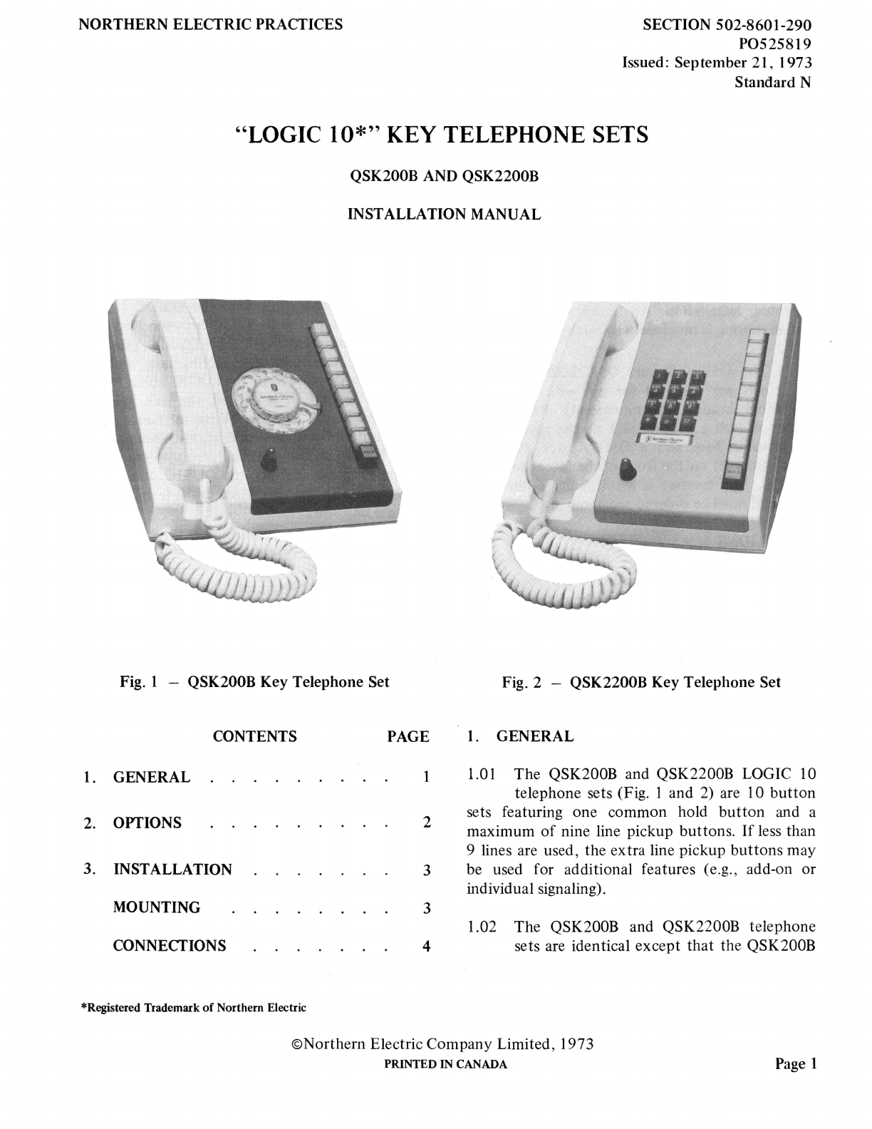
Fig. 1 - QSK200B Key Telephone Set Fig. 2 - QSK2200B Key Telephone Set
CONTENTS
1. GENERAL
2. OPTIONS
3. INSTALLATION
MOUNTING
CONNECTIONS
*Registered Trademark of Northern Electric
PAGE
1
2
3
3
4
1. GENERAL
1.01 The QSK200B and QSK2200B LOGIC 10
telephone sets (Fig. 1 and 2) are 10 button
sets featuring one common hold button and a
maximum of nine line pickup buttons. If less than
9 lines are used, the extra line pickup buttons may
be used for additional features (e.g., add-on or
individual signaling).
1.02 The QSK200B and QSK2200B telephone
sets are identical except that the QSK200B
©Northern Electric Company Limited, 1973
PRINTED IN CANADA Page 1

SECTION 502-8601-290
telephone set is equipped with a QDBIN rotary
dial while the QSK2200B telephone set is equipped
with a NE-3SQ3Ll DIGITONE* multifrequency
pushbutton dial.
1.03 The QSK200B and QSK2200B telephone
sets are designed for use with the NE-I AI,
NE-IA2, or NE-6A key telephone systems (KTS).
The sets cannot be used with the NE-IA KTS.
1.04 The QSK200B and QSK2200B telephone
sets are designed for desk-top or wall-
mounted installation. An accessory bracket for
wall-mounting is provided with each set.
I.OS The QSK200B and QSK2200B telephone
sets are designed for use with the QSR2
hands-free headset (or equivalent). Each set is
equipped with a headset jack on the right side of
the housing base and a QMJ7A jack mounting
switch (on-off) on the front of the faceplate below
the dial. The headset is a subscriber option (see
2.0 I) and must be ordered separately.
2. OPTIONS
2.01 The following features are subscriber
options. Refer to the schematic diagrams
(Fig. S and 6) and the conductor assignment
information (Table A) when converting the
telephone set for a particular option as specified
below and in Tables B through J.
(a) Buzzer. A QBXIA buzzer may be mounted
on the left-hand dial mounting bracket. The
buzzer should be connected to either the ringer
leads or the two spare leads for the station busy
lamp option, whichever are not being used. The
QBXIA buzzer operates on 10 V ac only.
(b) Station Busy Lamp. This feature may be
installed to provide station busy lamp
indication. Connection information for this
feature is given in Table B.
*Registered Trademark of Northern Electric
Page 2
(c) Ringer Cutoff This feature may be provided
by bending the stop next to the detent on
the ringer volume control until it completely
clears the rim of the ringer frame. This provides
a further position on the volume control which
prevents ringer armature movement.
(d) Hands-Free Telephone Operation. The
QUSIC COMPANION 3* hands-free unit is
designed for use with the QSK200B and
QSK2200B telephone sets. The QUS IC unit is
physically compatible with the LOGIC IO sets
and is equipped with a lS-pin connection plug
for plug-in attachment. The QUS IC plug fits
into a matching interconnecting jack which is
normally stored within the LOGIC IO set. When
QUS IC operation is desired, the jack must be
inserted in the left side of the set housing and
the unit and set connected as described in 3.08.
An NE-2012B transformer (or equivalent power
supply) is required for the QUSIC unit and is
connected to the unit through the telephone set
(see 3.08).
(e) External Speakerphone Operation. An NE-3
type speakerphone may be used with the
LOGIC IO telephone sets. The subscriber must
relinquish two line pickup positions to make
cord conductors available for speakerphone
installation. The QDB IN dial in the QSK200B
telephone set provides an additional set of
shunting contacts, which in turn provide the dial
muting required for NE-3 type speakerphone
operation. External speakerphone connection
information is given in Table C.
(f) / Hold Operation. This feature may be
installed in place of the regular hold feature.
Connection information is given in Table D.
(g) Headset Operation. A QSR2 type headset or
equivalent may be installed by making
minor changes in the telephone set (see 3.07).

(h) Individual Signaling. Momentary contacts
for individual signaling may be obtained by
removing the P0S14515 locking pin from the
key position which is to be converted and
making the wiring change given in Table E. The
momentary contact under the headset switch
may also be used for individual signaling (see
Fig. 5 or 6).
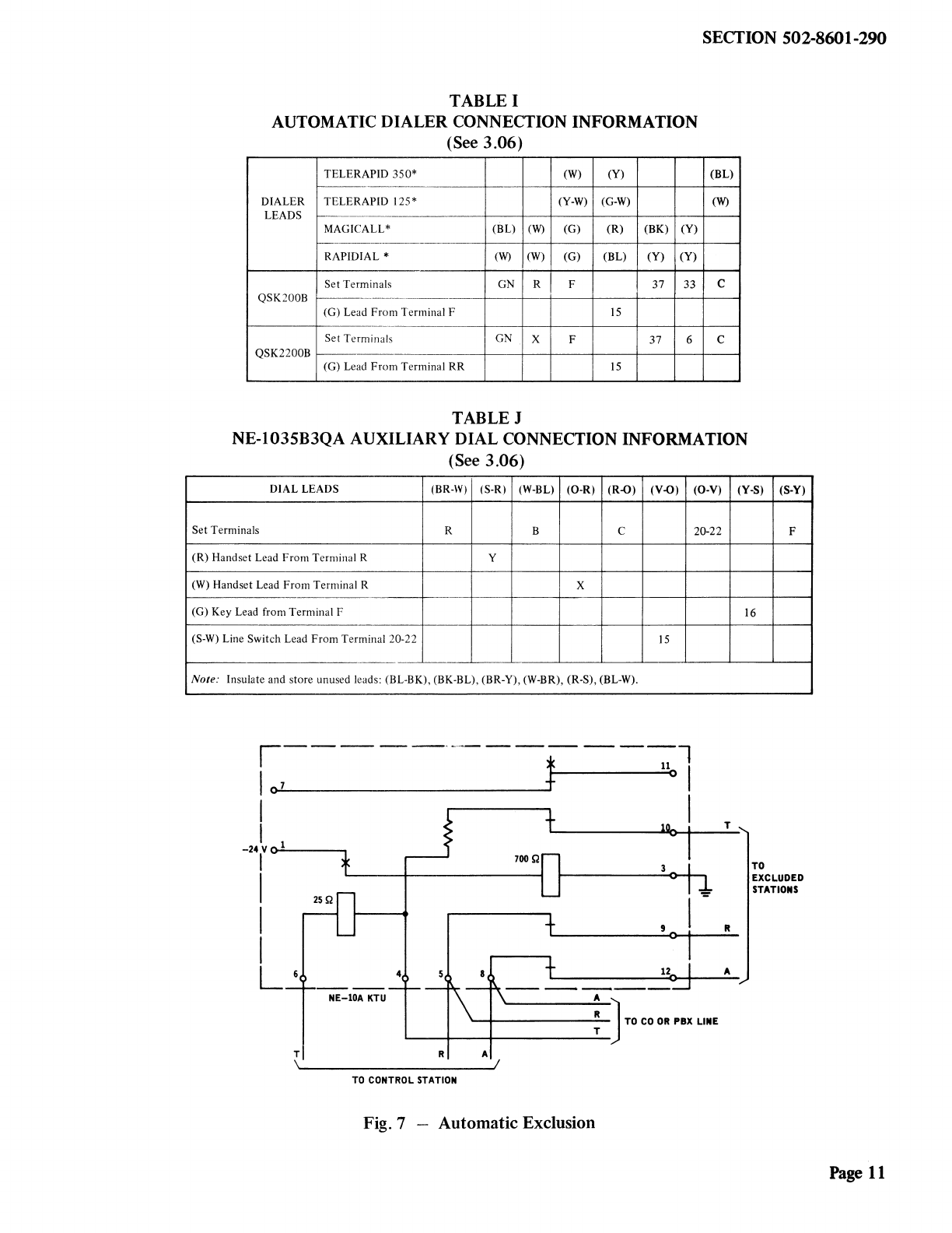
(i) Automatic Exclusion. This feature may be
obtained on one line by using an NE-10A
KTU (see Fig. 7). The feature provides
automatic cutoff of excluded stations whenever
the master station picks up the line associated
with the NE-lOA KTU.
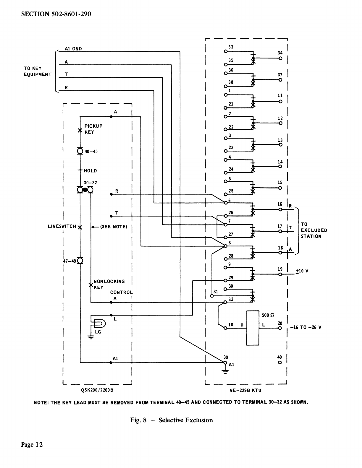
(j) Selective Exclusion. This feature may be
obtained by using an NE-229B KTU (see
Fig. 8). The feature provides exclusion only if
the exclusion pushbutton on the key is
depressed momentarily. Any button on the key
may be converted for control by removing the
appropriate AG lead from terminal 40-45,
connecting this lead on terminal 30-32, and
removing the P0S 14515 locking pin. The lamp
in the exclusion button lights when the
exclusion circuit is in operation. Exclusion is
removed automatically when the call is either
placed on hold or terminated. The exclusion
circuit is compatible with COMPANION 3,
headset, or handset operation.
(k) Add-On Operation. The add-on feature may
be obtained on two lines by using an
NE-237B KTU (see Fig. 9 and Table B). Any
button may be used but must be made
nonlocking by removing the locking pin. The
lamp in the add-on button will light when the
add-on circuit is in use. The add-on circuit is
released by pressing the add-on button again or
hanging up the handset. The add-on circuit is
compatible with COMPANION 3, headset, or
handset operation.
(1) Ringer. The ringer feature is connected to
position 1 as shipped but may be connected
to another position or as a common ringer by
changing the wiring according to Table F and
connecting to the R-R 1 and B-B1 leads at the
key equipment.
SECTION502-8601-290
(m)Amplifier. An NE-241QB amplifier may be
required when using an NE-52 type or
equipment headset. Connection information is
given in Table G.
(n) Voice Station Coupler. A QCTIA voice
station coupler may be installed to provide
an automatic answering facility. Connection
information for this feature is given in Table H.
(o) Automatic Dialer. A variety of automatic
dialers are compatible with the LOGIC 10
sets. Connection information is given in Table I.
(p) Auxiliary Dial. An NE-1035B3QA station
dial may be used with the QSK200B
telephone set if computer input of DIGITONE
signals is required. Connection information is
given in Table J.
3. INSTALLATION
MOUNTING
3.01 For desk-top installation, the sets should be
placed in a convenient location on the desk
and connected to the appropriate connector cable.
3.02 For vertical surface installation, it is
necessary to use the accessory mounting
bracket and knurled thumb screw which are
supplied with each set. The installation should be
performed as follows.
(a) Attach the mounting bracket to the
mounting surface using two No. 8 screws or
similar mounting hardware. (The mounting
hardware must be obtained locally.)
(b) Place the telephone set on the mounting
bracket so that the shoulder rivets enter the
corresponding keyhole slots in the base of the
telephone set (Fig. 10).
(c) Move the telephone set to the left as far as
possible so that the lower front mounting
hole is in line with the corresponding threaded
hole in the telephone set base (Fig. 10).
Page3

SECTION 502-8601-290
(d) Lock the telephone set in place by inserting
the knurled thumb screw through the
mounting bracket and into the threaded hole in
the base of the telephone set and tightening the
screw by hand.
3.03 When mounting the telephone set on a
vertical surface, the mounting cord is
directed downward from the cord exit hole in the
base of the set so that it can be fastened to the
mounting surface where required.
CONNECTIONS
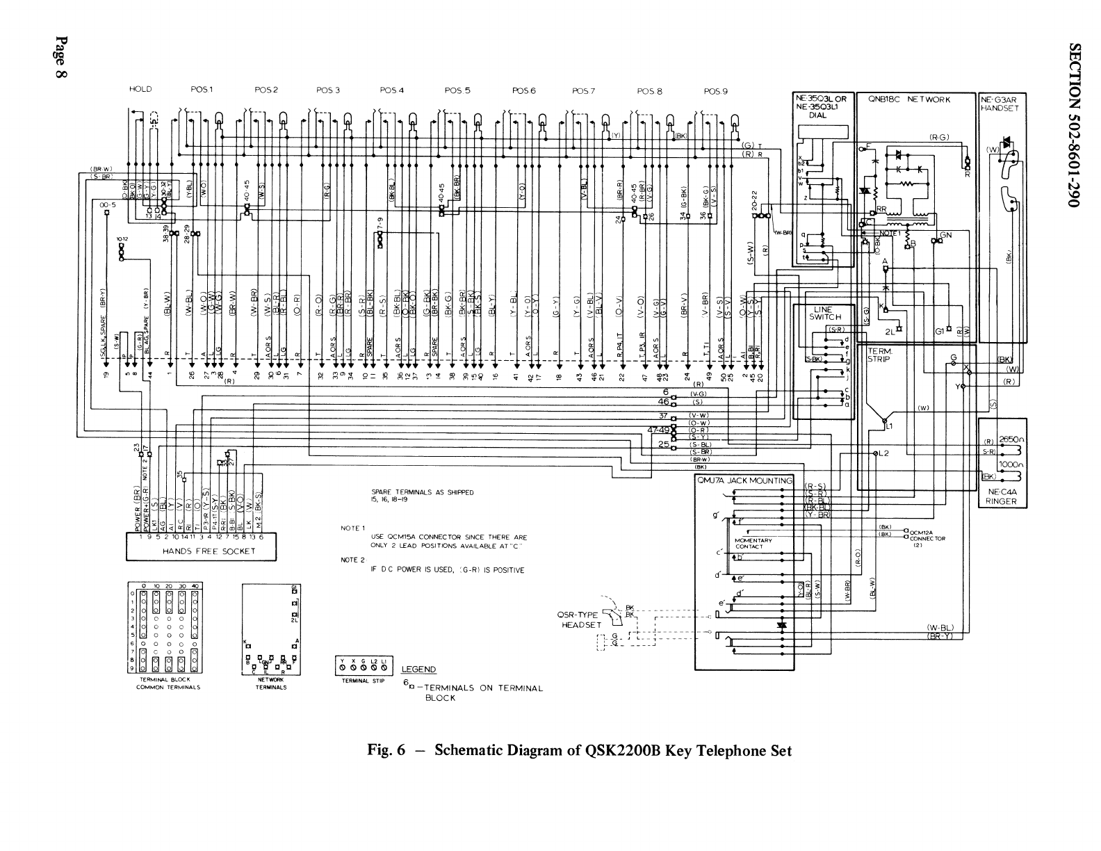
3.04 Connection information for the QSK200B
and QSK2200B telephone sets is shown in
Fig. 5 and 6. See Table A for cord assignment
information. See Tables B through J for wiring of
options.
Caution: The connection diagrams and tables
must be followed closely, since wiring of the
QSK200B and QSK2200B telephone sets is
not standard due to the limited number of
cord conductors available.
3.05 The faceplate and housing cover must be
removed when converting the telephone set
wiring for subscriber options.
Removal
(a) Release the faceplate catch (see Fig. 11) by
inserting the NS-16750 L3 releaser into the
release hole located on the lower front edge of
the housing cover.
(b) Lift upward and forward on the faceplate
until the locating tabs at the rear of the
faceplate are disengaged from the housing cover.
(c) Loosen the two captive retaining screws
until they are disengaged from the threaded
posts on the housing base. The cover can then be
removed.
Replacement
(a) Place the cover in position.
Page 4
(b) Tighten the captive retaining screws.
Caution: Do not exert undue force when
tightening the captive retaining screws.
(c) Engage the two tabs at the rear of the
faceplate in the housing cover.
(d) Align the single front catch with the hole in
front of the cover, and press until the front
catch snaps in place.
3.06 When making the conversions as specified in
Tables B through J, the following guidelines
should be observed.
(a) If more connection positions are required
than are available, use QCMISA connectors
(Fig. 3) for the additional positions.
(b) If no terminal is available for the connection
of two spade-tipped leads, use a QCM12A
connector (Fig. 3).
c---------'(
QCM15A
Q
QCM12A
Fig. 3 - QCMlSA and QCM12A Connectors
Headset Connection
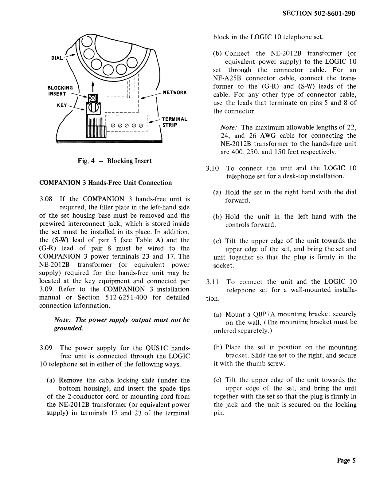
3.07 If headset operation is required, remove the
faceplate and cover per 3.05 and remove the
yellow blocking insert (see Fig. 4) from the turn
switch by pulling it straight out toward the dial.
Insert the headset plug into the jack located on the
lower right-hand side of the set and at the same
time rotate the control key, located in the lower
left-hand corner of the faceplate, 90 degrees in a
clockwise direction. Dial tone will be heard in the
headset receiver and dialing will be possible
without removing the handset.
DIAL
t I I I
BLOCKING 1: I 1
INSERT -----~r:.----:NETWORK
KEY--)_ : I
_______ J
---------7 1..---TERMINAL
0 0 0 0 0 : STRIP
__________ _j
Fig. 4 - Blocking Insert
COMPANION 3 Hands-Free Unit Connection
3.08 If the COMPANION3 hands-free unit is
required, the filler plate in the left-hand side
of the set housing base must be removed and the
prewired interconnect jack, which is stored inside
the set must be installed in its place. In addition,
the (S-W) lead of pair 5 (see Table A) and the
(G-R) lead of pair 8 must be wired to the
COMPANION3 power terminals 23 and 17. The
NE-2012B transformer (or equivalent power
supply) required for the hands-free unit may be
located at the key equipment and connected per
3.09. Refer to the COMPANION 3 installation
manual or Section 512-6251-400 for detailed
connection information.
Note: The power supply output must not be
grounded.
3.09 The power supply for the QUS 1C hands-
free unit is connected through the LOGIC
10 telephone set in either of the following ways.
(a) Remove the cable locking slide (under the
bottom housing), and insert the spade tips
of the 2-conductor cord or mounting cord from
the NE-2012B transformer (or equivalent power
supply) in terminals 17 and 23 of the terminal
SECTION502-8601-290
block in the LOGIC 10 telephone set.
(b) Connect the NE-2012B transformer (or
equivalent power supply) to the LOGIC 10
set through the connector cable. For an
NE-A25B connector cable, connect the trans-
former to the (G-R) and (S-W) leads of the
cable. For any other type of connector cable,
use the leads that terminate on pins 5 and 8 of
the connector.
Note: The maximum allowable lengths of 22,
24, and 26 AWG cable for connecting the
NE-2012B transformer to the hands-free unit
are 400, 250, and 150 feet respectively.
3.10 To connect the unit and the LOGIC 10
telephone set for a desk-top installation.
(a) Hold the set in the right hand with the dial
forward.
(b) Hold the unit in the left hand with the
controls forward.
(c) Tilt the upper edge of the unit towards the
upper edge of the set, and bring the set and
unit together so that the plug is firmly in the
socket.
3.11 To connect the unit and the LOGIC 10
telephone set for a wall-mounted installa-
tion.
(a) Mount a QBP7A mounting bracket securely
on the wall. (The mounting bracket must be
ordered separetely .)
(b) Place the set in position on the mounting
bracket. Slide the set to the right, and secure
it with the thumb screw.
(c) Tilt the upper edge of the unit towards the
upper edge of the set, and bring the unit
together with the set so that the plug is firmly in
the jack and the unit is secured on the locking
pin.
Page5

SECTION 502-8601-290
TABLE A
QSK200B AND QSK2200B TELEPHONE SET CONDUCTOR ASSIGNMENT
QSK200/2200B SET NEDS0QE CORD CONNECTOR CONNECTINGBLOCK
CABLE
LINE FUNCTION COLOR TER-- PLUG CON-- COLOR PAIR PLUG CON-- COLOR PAIR LEAD LINE
MINAL NECTOR NECTOR
T (W--BL) 28--29 26 26 (W--BL) 26 26 (W--BL) T
R (BL--W) 38--39 I I (BL--W) I I I (BL--W) 1 R
I A (W--O) 27 27 (W--O) 2 27 27 (W--0) 2 A I
Al (O--W) 47-49 2 2 (O--W) 2 2 (O--W) Al
LG (W--G) 28 28 (W--G) 3 28 28 (W--G) 3 LG
L (G--W) 3 3 (G--W) 3 3 (G--W) L
T (W--BR) 29 29 (W--BR) 4 29 29 (W--BR) 4 T
R (BR--W) 4 4 (BR--W) 4 4 (BR--W) R
A,S (W--S) 30 30 (W--S) 5 30 30 (W--S) 5 A,S
SPARE (S--W) 23 5 5 (S--W) 5 5 (S--W) *
2 2
LG (R--BL) 31 31 (R--BL) 31 31 (R--BL) LG
L (BL·R) 6 6 (BL·R) 6 6 6 (BL--R) 6 L
T (R--O) 32 32 (R--O) 7 32 32 (R--O) T
R (O--R) 7 7 (O--R) 7 7 (O--R) 7 R
A,S (R--G) 33 33 (R--G) 8 33 33 (R--G) 8 A,S
SPARE (G--R) 17 8 8 (G--R) 8 8 (G--R) *
3 LG (R--BR) 34 34 (R--BR) 34 34 (R--BR) LG ]
L (BR--R) 9 9 (BR--R) 9 9 9 (BR--R) 9 L
T (R--S) 35 35 (R--S) 35 35 (R--S) T
R (S--R) IO 10 (S--R) 10 10 10 (S--R) 10 R
A,S (BK--BL) 36 36 (BK--BL) 11 36 36 (BK--BL) 11 A,S
4 SPARE (BL--BK) 7..9 11 I I (BL--BK) 11 11 (BL--BK) SPARE 4
LG (BK--O) 37 37 (BK-0) 37 37 (BK--O) LG
L (O--BK) 12 12 (O--BK) 12 12 12 (O--BK) 12 L
T (BK--G) 38 38 (BK--G) 38 38 (BK--G) T
R (G--BK) 13 13 (G--BK) 13 13 13 (G--BK) 13 R
5 A,S (BK--BR) 39 39 (BK--BR) 14 39 39 (BK--BR) 14 A,S 5
SPARE (BR--BK) 7..9 14 14 (BR--BK) 14 14 (BR--BK) SPARE
LG (BK--S) 40 40 (BK--S) 40 40 (BK--S) 15 LG
L (S--BK) 15 15 (S--BK) 15 15 15 (S--BK) L
T (Y--BL) 41 41 (Y--BL) 41 41 (Y--BL) T
R (BL--Y) 16 16 (BL--Y) 16 16 16 (BL--Y) 16 R
6 6
A,S (Y--O) 42 42 (Y--O) 42 4c (Y--O) A,S
L (O--Y) 17 17 (O--Y) 17 17 17 (0--Y) I7 L
T (Y--G) 43 43 (Y--G) 43 43 iY--G) T
R (G--Y) 18 18 (G--Y) 18 18 18 (G--Y) 18 R
b L,SP (Y--BR) 10--12 44 44 (Y--BR) 19 44 44 (Y--BRl 19 BL, SPARE
7 SG,SP (BR--Y) 00--5 19 19 (BR-Y) 19 19 !BR--Y) SG, SPARE 7
R-Rl (Y--S) GI 45 45 (Y--S) 45 45 (Y--S) R--Rl
B--Bl (S--Y) 2L 20 20 (S--Y) 20 20 20 (S-Y) 20 B--B1
A,S (V--BL) 46 46 (V--BL) 21 46 46 (V--BL) A,S
L (BL--V) 21 21 (BL-V) 21 21 (BL--V) 21 L
T,SP (V-0) 26 47 47 (V-0) 47 47 (V-O) T,SPARE
R,SP (O..V) 24 22 22 (O-V) 22 22 22 (O--V) 22 R, SPARE
8 8
A,S (V--G) 48 48 (V-G) 23 48 48 (V-G) 23 A,S
L (G--V) 23 23 (G--V) 23 23 (G--V) L
T,SP (V--BR) 36 49 49 (V--BR) 49 49 (V--BR) T, SPARE
R,SP (BR-V) 34 24 24 (BR--V) 24 24 24 (BR--V) 24 R, SPARE
9 9
A,S (V--S) 50 50 (V-S) 50 50 (V--S) A,S
L (S--V) 25 25 (S-V) 25 25 25 (S-V) 25 L
*See 3.08
Page 6

i
-.,l
HOLD POS 1 POS 2 POS 3 POS. 4 POS 5 POS 6 POS7 POSS POS9 ODB1N
DIAL ONB18C NETWORK NE-G3AR
HANDSET
IBRw·,
I--, ,-,
:ii:
r'
(S BRI
~~~~
I[]
I
;~~~~r~1~
~
11
~
rll111
~
an11
~
an11
~
anuam1
~
r[1111~-..anu-«ami
~
"".1 .~ =,,_,,_........,... NOTE~'
1
R,
~
~
1-
~ ~
LO
~
~
~
1:1 'a
~, I~ ril~~'"-I
;;
'1'
s 'cl'"
005
Q
~
l;I I~
a:
11 saHI Ill 1~1Ill I 1
1 D-
>
~
00::J>J
~
7- "''
~2:
°ii 11 I 11 ;;:
11~1
10-12
n
~~~
~
~
n ni
a:
~
ila'
~I~
".: ;~
~~~~~
II~I
~l~~
~1~1
~~
~!I~Iii ~II
~
I
~
%1j ~I!I:I;:
"
C/1-~<;,~";,-
"I a:
----~ l')
--•i"rH--"
'!' ; ;:BI~r'"l re s1
~
L__
lM-~l--:l-lli-"'l~l~1JHi-1~1~l-\:isi-;
R;
~
lDM r--.
~
~rn;; $? =
~
~~M
~
~
~
~~~
~
'"
a:
1-I ~I_J
---t--
►,
;; Nr--
st- !"
'"
0-
1-( ~l_j
r<) WN
" "
st
N "'
N
OI '-"I>
;; i :
';;,
~7
~i
:1· >l>t·
¢' r<) er. -
-~--~}J___
~
gj r-- "'"' "
" .;N N
~
~
47-49
~
:g1
~] cnl>
2: >l<n
~~]
i=J"51I Jiiilii:
- _~J
-~~
-
~~
cr·i
0) QI() N!DO
~
L()N <:tCIJ
_ifil
ill
(BK)
IW
(S-W) A~
-t=
l£11
t 11
::rg
1111'--------rG
~~t:::l "rj:
N jll
~
I a I
~
r ISBB) <t!H ... I I I II ' ' a
25_
~
I
~
'.:':":-Wl
-
~
:
~~~~~ci~:!l~2i~
NOTE 1
SPARE TERMINALS AS SHIPPED
15, 16, 18-19, 6
OMJ 7A JACK M:)(JNTING
I
9,,.-}r
(R-Sl I
rs::m
1
~
11
1 11'I
[BKl
I m1
11r(TX
·1- - -- ~"' ;---s:1~~1°11"'
c<l') - U - M ~19'1"?1~1~1N
_J <.( ..J. o::ir 1- a.. a.. a: m l1l _, '.L
1 9 5 2 10 14 11 3 4 12 7 15 8 13 6 ONLY 4 LEAD POSITIONS ARE AVAILABLE AT ..R
PLACE 3 IN "R'; 3 ON ''X" OF TERMINAL STRIP AND
CONNECT 'x" TO.'R" WITH A JUMPER l EAO
t
l',,1Qt,,1EN1ARY
b CONIACT
(BK) 00CM12A
ITT.
~
..,,.
HANDS FREE SOCKET
010203040
;;~~~~~
4 ·:J O O lJ
'5 0 0 0 0
II~~~~
ra
TERMINAL BLOCK
co~~IVION TERMINAL':,
GI
a
:1
2L
K A
a a
0 C O O C
BGNRRF
C C C C
_C_'L __ R
NETWORK
TERMINALS
c I16' : I ! I '
er
NOTE 2
IF DC POWER IS USED, , G- RI IS POSITIVE e~ • I A'·.
,§~~II I i
.'.JI
~
(W-BU
mi:i:vr
\ sK t e 'if I
~
II 1
OSR-TYPE ~Eir.- --r---_-_-_-:.-::.-nJ l
HEADSE~ 1 G r-~--:-----=-
~
LFY::_::.1------ u,:):
Cb
Y X G L2 LI
0 0 0 0 0 LEGEND
TERMINAL STRIP 6tl _ TERMINALS ON TERMINAL
BLOCK
Fig. S -Schematic Diagramof QSK200B Key Telephone Set
ii
,J2650n
I~ 1000n
IBK)':-7
NE·C4A
RINGER
~
§
z
Vi
0
~
00
g
-
f&
0
?
00
HOLD POS1 POS2 POS 3 POS4 POS 5 FDS6 FDS 7 POSS POS9 0NB18C NETWORK
~i'r1-hR -- -- rr1Rr[hll~IY{fhll~IB{rhll~(GIT
1
]lRr[I1jJRr[I111R[ ll
d-- NE35O3LOR
NE-35O3L1
DIAL
L In IR-Gl
(BR·WJ
IS· BRI "\Iar1:.:r~f:Si':ll:JI16
~i61~bJ~IM I !
~
00-5 ,1aa-ti
'I0•12 "'??"'
~
<';JI
"' "'
-, N
ii ii
~
co >-
~
- - [11
w w
"'
~
~
- _e;_
3 "'"
~
_JJl~;i"'
~ii;
f----1 <i:I..JISiO'.I
l I I I I T I I
~~la~~
"''
HJl)"11
~
[_~
~
~M~(R~
~
g<D;;i r--
~6irlIl~Q111
~
~
!0~~~
~Q-~3:;m~Q3
~
-;1~l~ p,-1-l"'I~I"'
n~~:,~rrJh:iii;i:
1 9 5 2 ,o1411 3 4 12 7 ,5 8 13 6 I
HANDS FREE SOCKET
010203040
;~0~~~1◊
3 0 0 0 0
4 0 0 0 C
500000
600000 'a
~
:1
2L
A
0
71'.:!COO~
:~~~~bl
f/~'fliio.9
TERMINAi.. B1..0CK
COMMON TERMINAi..$
L.1!:..____ft
NETWORK
TERMINAI..S
"'
~
~
:
rt
-~I·irt"-~iiJI~I"'(91·1-,;::
1
, 1 • 1
~
I :i:::I I I 0:
~
S;'. I _'_J
n::: 0:: 0:: lllCO 0:: !!!
~
ID
~
£f)-
~
lo
>-:J
~
~~
~I2:: >-
2
~l]Jj~-!cl!L~J_~)c -"'l~-~ltJH-J-~l-~~---
{\J 1"10) '<t o- I()
M M M ,- - I"'!
~~~
~
~
~
~
~~
'f! V N ,._
..-
NOTE 1
NOTE 2
SPARE TERMINALS AS SHIPPED
15, 16, 18-19
USE 0CM15A CONNECTOR SINCE THERE ARE
ONLY 2 LEAD POSITIONS AVAILABLE AT "C'
IF DC POWER IS USED, : G-Rl IS POSITIVE
~
-1-:il;,
'-?cp
~
2:: 2:.~
"
H ~!
"' "'-
-, ,;fN
~I
Q
--t-t---t--1~~~
~
01co~I
' ''
2 ~{!
>
~
0'.1-~
~
(0 (f)> >
I 1- I I .I I
> 2:U) ..__,>-V~I
<;I
---.----.n,
~
tn =
a
~~
I,1i
A
ikl3N
I
'=
_JLJj~L~
--~-i}-1~~'
N
N
.....
~
"'"'
., """'
6
46~
~
:-_4';::I~
~0-
., "'
"' <t
JBl
(V.G)
.al
lV'w;
(O-W)
(O-R
LS__:_U_
Q,O
"'"' N"10
""'
(
L1
(S-BU L2
" S-BR}
(BR-W)
(BK)
!OMJ7A JACK MOUNTINGi
t
g· 11{ li
~g::~T;RY
~
a c~~NECTOR
II • 11 11 11 I~OCMl2A
C •6'. : I
~
d'-"------+--4-++--l--+-' DC
<Il
OSR-TYPE ~;.,- r --~1--e· :'.
HEADSE\f ;_\j:___:-_:-_:---~ IW-BU
~
-~ .
31
al
YXGL21..1
(I) (I) (I) (I) (I) I LEGEND
TERMINALST!P 60 -TERMINALS ON TERMINAL
BLOCK
Fig. 6 -Schematic Diagram of QSK2200B Key Telephone Set
Cl.l
t!1
(")
~
NE-G3AR I 0
HANDSET ~
Ul
0
u~ N
I
00
0',
0
-
I
N
~
\0
0
"
"'

SECTION 502-8601-290
TABLEB
STATION BUSY LAMP AND ADD-ON CONNECTION INFORMATION
(See 3.06)
LEAD STATION BUSY LAMP ADD-ON*
Hold Key (G-W) Remove from 30-32
and connect to 10-12 -
Mounting Cord (Y-BR) Remove from 10-12 -
and connect to 30-32
Diode Assembly 30-32)
►
I
P05227]8 Go-12 30-32)
►
I
(10-12
*See Fig. 9
TABLEC
EXTERNAL SPEAKERPHONE CONNECTION INFORMATION
(See 3.06)
SPEAKERPHONE LEAD REMOVE CONNECT
LEADS COLOR FROM TERMINAL TO TERMINAL
Tl V-BR 36 6tt
RR**
Rl BR-V 34 20-22
30-32
AG Y-BR 10-12 I0-I 2t
LK BL-BK 7-9 46
35tt
P3 or IR V-O 26 37**
P4 or IT 0-V 24 33
Al O-W 47-49
ttQSK2200B **QSK200B t If Station Busy Lamp or Add-On is provided
Note: If the speakerphone control is located at the station, connect the appropriate speakerphone
function lead to the indicated terminal by means of a suitable spade tip ended cord, e.g., a
NE-DI0L-* cord.
Hold
Key
TABLED
I HOLD CONNECTION INFORMATION
(See 3.06)
LEAD REMOVE CONNECT
FROM TERMINAL TO TERMINAL
(O-BK) 30-32 33
(G-W) 30-32 40-45
(BK-0) 40-45 30-32
SP-(BR-BK) or Spare 7-9 33
Page 9
SECTION S02-8601-290
Page 10
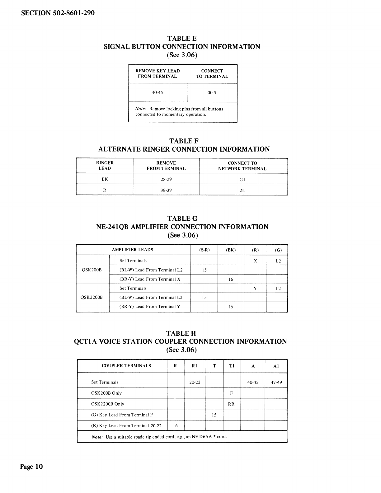
TABLEE
SIGNAL BUTTON CONNECTION INFORMATION
(See 3.06)
REMOVEKEY LEAD CONNECT
FROMTERMINAL TOTERMINAL
40-45 00-5
Note: Remove locking pins from all buttons
connected to momentary operation.
TABLEF
ALTERNATE RINGER CONNECTION INFORMATION
RINGER REMOVE CONNECTTO
LEAD FROMTERMINAL NETWORKTERMINAL
BK 28-29 GI
R 38-39 2L
TABLEG
NE-241QB AMPLIFIER CONNECTION INFORMATION
(See 3.06)
AMPLIFIERLEADS (S-R) (BK) (R)
Set Terminals X
QSK200B (BL-W) Lead From Terminal L2 15
(BR-Y) Lead From Terminal X 16
Set Terminals y
QSK2200B (BL-W) Lead From Terminal L2 15
(BR-Y) Lead From Terminal Y 16
TABLEH
(G)
L2
L2
QCTlA VOICE STATION COUPLER CONNECTION INFORMATION
(See 3.06)
COUPLERTERMINALS R RI T Tl A Al
Set Terminals 20-22 40-45 47-49
QSK200B Only F
QSK2200B Only RR
(G) Key Lead From Terminal F 15
(R) Key Lead From Terminal 20-22 16
Note: Use a suitable spade tip ended cord, e.g., an NE-D6AA-* cord.
SECTION S02-8601-290
TABLE I
AUTOMATIC DIALER CONNECTION INFORMATION
(See 3.06)
TELERAPID 350* (W) (Y)
DIALER TELERAPID 125* (Y-W) (G-W)
LEADS -·--
MAGJCALL* (BL) (W) (G) (R) (BK) (Y)
RAPIDIAL * (W) (W) (G) (BL) (Y) (Y)
Set Terminals GN R F 37 33
QSK200B ~-----
(G) Lead From Terminal F 15
Set Terminals GN X F 37 6
QSK2200B (G) Lead From Terminal RR 15
TABLE J
(BL)
(W)
C
C
NE-1035B3QA AUXILIARY DIAL CONNECTION INFORMATION
(See 3.06)
DIAL LEADS (BR-IV) (S-R) (W•BL) (O·R) (R-0) (Y-0)
Set Terminals R B C
(R) Handset Lead From Terminal R y
(W) Handset Lead From Terminal R X
(G) Key Lead from Terminal f
(S-W) Line Switch Lead From Terminal 20-22 15
Note: Insulate and store unused leads: (BL-BK), (BK-BL), (BR-Y), (W-BR), (R-S), (BL-W).
,----------------- 11 7
I01 + 0 I
I .----------. I
I
-24VQ--------,
I
I
I
I
L_6-
700 Q
12
(O·Y)
20-22
NE-lOA KTU A
~-------~-] TO CO OR PBX LINE
T R A
TO CONTROL STATION
Fig. 7 - Automatic Exclusion
T
R
A
(Y·S) (S-Y)
F
16
TO
EXCLUDED
STATIONS
Page 11
SECTION 502-8601-290
Al GND
A
TO KEY
EQUIPMENT T
R
r- -- -,
I A
I PICKUP
I KEY
I 40-45
I
I HOLD
30-32
I R
I
I T
LINESWITCH (SEE NOTE)
I
I
I
47-49
I
I NONLOCKING
KEY
I CONTROL
A I
I
I L
I -
I
I Al
I
L __ -- _J
QSK200/2200B
,-- -----,
33
: 35 l 34
0
:::l 37
0
1
:21 l 11
0
2
:22 l 12
0
3
:23 l 13
0
l 14
0
15
0
16 R
17 T TO
EXCLUDED
18 IA
STATION
19 ±10 V
20
10 U
500Q
L , -16 TO -26 V
Al 40
0
L _____ _j
NE-229B KTU
NOTE: THE KEY LEAD MUST BE REMOVED FROMTERMINAL 40-45 AND CONNECTED TO TERMINAL 30-32 AS SHOWN.
Fig. 8 - Selective Exclusion
Page 12

~
~
-
w
CO LINE 2
/ \
l? Ro
,----------
1 23 S 7
0 i 25
I 2a~
_11
11
I _12
II
I
I
, - 21
I -
I _22
-.~
I
I _13
I
I
l 1
~
2_ I
2
I l
~
I
7_ I
II --., I
2
1• Ia_
~
): 3_
+ " I
9_
- I
I
~
I
202C OR 230ARD-t-, I * 11
1
,....,--e,:k 4 I
n
TU
~
~INE 2 u-..-- I .l..
I _19
-14 TO -26V DC I
I~
LAMPSUPPLY I
~
10
LJ
~
..... 16_ I
1-1 500 Q
~
I
5
6
15 I
L ___________ .J
NE-237B KTU
CO LINE 1
T9 R9
202C OR 230A
KTU LINE 1
T R A
0 0 O
r-------,
I
I
+2-o26 l
~
1 LINE 1
IA
~27
lI..o29]
II II :::,:LINEl
I
I
I
~
'A' LEAD OF NONLOCKINGKEY LINE 8/9
LAMP LEAD OF NONLOCKING4i25 NONLOCKING
KEY
40-45
LG HOLD
30-32
(Y-BR) IBL 10-12 LINESWITCH
I 44
IA1 47-49
2
L _______ J
QSK200/2200B
Fig. 9 - Add-On Circuit
Cl'.!
trl
~
-
0
z
Vt
0
N
I
00
°'
0
-
N
1.0
0

SECTION 502-8601-290
Page 14
14 Pages
TELEPHONE SET TELEPHONE SET WALL MOUNTING HOLES
(REAR VIEW) KEY HOLE MOUNTING SLOTS -~I
•
@)
@)
0 0
D D
MOUNTING CORD
[] []
~
D LOWERFRONT 0
MOUNTING HOLE 0
~
-
---- -//~c:ffl
-t
I KNURLED
THUMB SCREW
ACCESSORY WALL MOUNTING BRACKET
(REAR VIEW)
Fig. 10 - Method of Mounting QSK200B or QSK2200B
Telephone Set to Wall
Fig. 11 - Faceplate Removal
This manual suits for next models
2
Table of contents
Other NORTHERN ELECTRIC Telephone manuals


