NORTHERN ELECTRIC CENTURION Series User manual

TCI Library https://www.telephonecollectors.info/
NORTHERN ELECTRICPRACTICES
NOTE:
-SECTION 506-4001-290
P0521249
Issue 1, September 1973
Standard N
WHEN4018OR2401aSETS
ARESUPPLIEDOMIT3,05
ANDSUBSTITUTE
11
B" IN
ALLPLACESREFERREDTO
AS''A"MODELsosI
"CENTURION*"- COINTELEPHONESETS
QSD401A AND QSD2401A TYPES
INSTALLATION MANUAL
Fig. 1 - CENTURION Coin Telephone
Set Type QSD401 A
*Registered Trademark of Northern Electric
Fig. 2 - CENTURION Coin Telephone
Set Type 2401A
©Northern Electric Company Limited, 1973
PRINTED IN CANADA Page 1

TCI Library https://www.telephonecollectors.info/
SECTION 506-4001-290
1. GENERAL
1.01 This manual describes the QSD401A and
QSD240 IA CENTURION semi-postpay,
single coin slot telephone sets. Dismantling and
assembling information is given to facilitate
installation of the coin telephone sets.
1.02 For detailed description, installation,
maintenance, and repair information, refer
to Section 506-4001-200 and 506-4001-500.
2. DESCRIPTION
2.01 The CENTURION coin telephone set type
QSD401A (Fig. 1) is equipped with a rotary
dial, and the type QSD2401A (Fig. 2) is equipped
with a 12-button DIGITONE* dial.
2.02 The CENTURION coin telephone set can be
converted from rotary dialing to
DIGITONE dialing or vice versa, by interchanging
the dial and housing assembly and the hood unit
assembly. The components mountid on the
housing unit assembly are identical for both the
QSD401A and QSD2401A.
2.03 The sets are equipped with an electronic
variable initial rate coin totalizer (VIR) on
the printed circuit board (PCB) assembly. The VIR
totalizer can be modified to increase the initial rate
from 5-cents up to 40-cents in increments of
5-cents.
2.04 The set weighs approximately 50 pounds
(22. 7 kilograms). The overall dimensions are
shown in Fig. 3.
3. SEMI-POSTPAYOPERATION
3.0 l When the handset is lifted off-hook battery
and ground are connected to the set (-48 V
battery to the ring side of the line, ground to the
tip side of the line). Dial tone is heard and dialing
may proceed.
3.02 When the called party answers, the central
office provides battery reversal to the coin
telephone. When the battery polarity is reversed a
*Registered Trademark of Northern Electric
Page 2
diode in series with the transmitter prevents
current from passing through the transmitter. In
this way transmission is prevented.
3.03 Coins must now be deposited to a value
equal to or exceeding the initial rate. The
coin signaling and totalizer circuit, which is
protected by a polarity guard, will respond to the
deposited coins. When the initial rate is reached the
totalizer latching relay (LRT) operates. The
operation of LRT shunts out the diode in series
with the transmitter, thus enabling transmission.
3.04 Battery reversal does not occur on calls to
the operator and transmission is permitted
at all times.
\
6.41
Fig. 3 -Rear View of CENTURION
Coin Telephone Set
TCI Library https://www.telephonecollectors.info/
3.05 The totalizer latching relay is reset on each
call by momentarily connecting the relay
reset coil in series with the loop during the
operation of the dial.
3.06 All coins deposited proceed directly to the
cash receptacle and cannot be returned to
the customer.
4. ORDERING INFORMATION
4.01 The CENTURION coin telephone sets are
ordered as follows:
Coin Telephone Set QSD401A
Coin Telephone Set QSD240 IA.
The color suffix shown in Table A follows the coin
telephone set code number.
COLOR
Black
Brown
Blue
Green
TABLE A
COLOR SUFFIX
SUFFIX
-03
-26
-27
-28
4.02 A security kit may be ordered as a complete
kit or individual items may be ordered from
the codes listed in Table B.
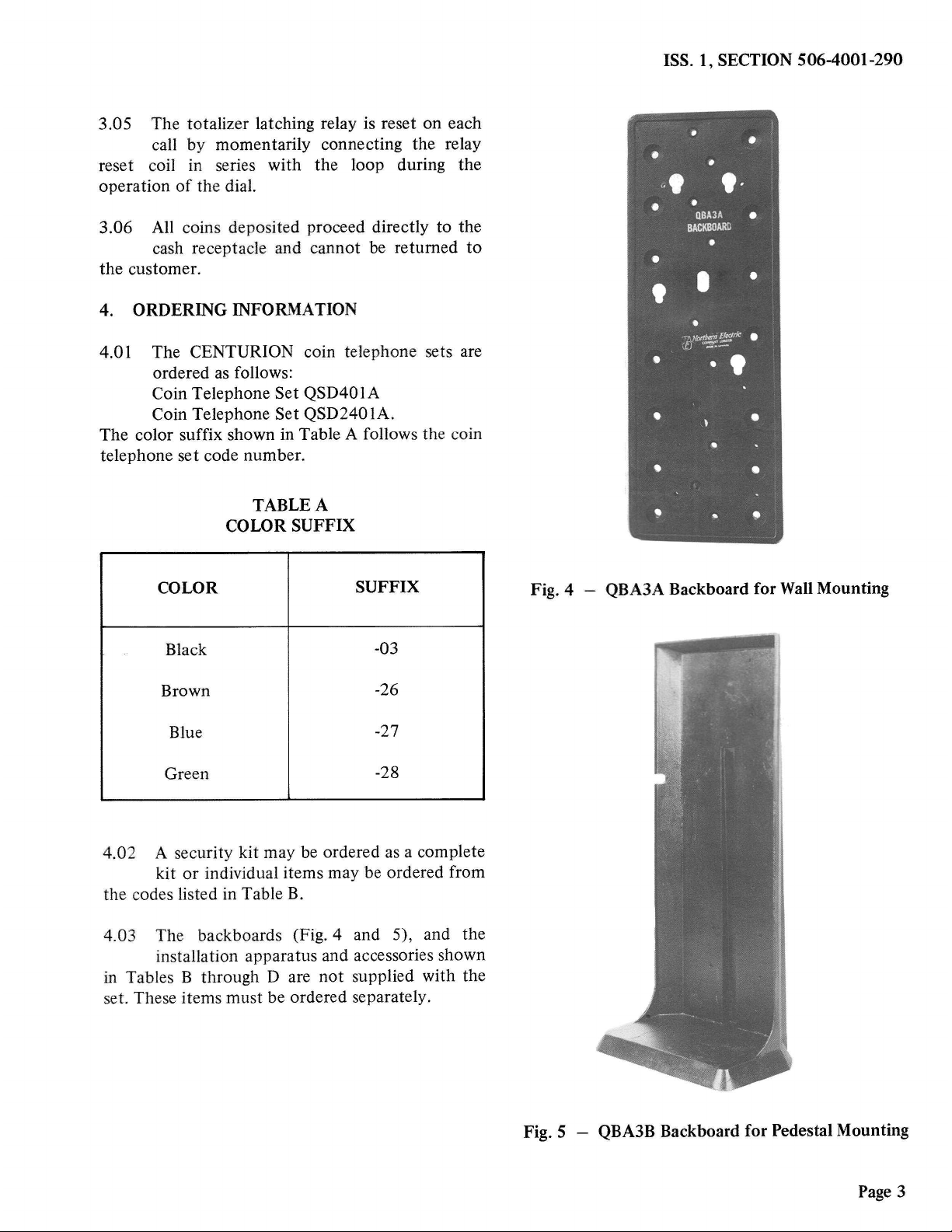
4.03 The backboards (Fig. 4 and 5), and the
installation apparatus and accessories shown
in Tables B through D are not supplied with the
set. These items must be ordered separately.
ISS. 1, SECTION 506-4001-290
•
•
• •
,.,,
.
• •
QBA3A •
BACKBOARD
•
•
I •
' •
"(f/1°",1':!:j.~
•
---
• • I
•
•
-•
-..
~
Fig. 4 -QBA3A Backboard for WallMounting
Fig. 5 -QBA3B Backboard for Pedestal Mounting
Page 3

TCI Library https://www.telephonecollectors.info/
SECTION 506-4001-290
KIT
TABLEB
SECURITY KITS AND SEPARATELY ORDERED ITEMS FOR
QSD401A AND QSD2401A TYPE SETS
ITEM ITEM
DESIGNATION CODE DESCRIPTION
CODE
NE-22QC Cash compartment lock with 2 keys
QKBIA NE-22QD Cover unit assembly lock (Note I)
Security Kit NE-IB Standard size cash receptacle
NE-IC Receptacle cover
NE-22QC Cash compartment lock with 2 keys
QKB2A NE-22QD Cover unit assembly lock (Note I)
Security Kit NE-IC Oversize cash receptacle
NE-IC Receptacle cover
P050I738 Vault liner assembly
Accessory P0I0E070 Mounting studs (4 required)
Equipment
-
Key for NE-22QD lock cover unit assembly
-Reserved lock combination (Note 2)
Notes:
I.
2.
Page4
Keys for the NE-22QD lock are not supplied with the lock and must be ordered separately in
the quantity required.
Security kits are available with reserved lock combinations for the NE-22QD lock, on a
special order basis.
TOOL CODE
Tool, P0896911
Tool, QTH43A
TABLE C
INSTALLATION AND MAINTENANCE TOOLS FOR
QSD401A AND QSD2401A
USE
To remove hood, cover assemblies, and coin receptacle door.
The tool is shown in Fig. 6.
To support the cover unit assembly in the open position.

TCI Library https://www.telephonecollectors.info/
ISS. 1, SECTION 506-4001-290
TABLED
FASTENERSFOR COINTELEPHONESET
BACKBOARDS
SIZEAND MINIMUM
MOUNTING HOLESIZE TYPEOF NUMBER
SURFACE REQUIRED FASTENERS OF
FASTENERS
Softwood 1/8 inch or No.30 1-3/4 inch No.14 7
F.H. wood screw
Hardwood 1/8 inch or No.30 1-1/4 inch No.14 7
F.H. wood screw
Masonry 2 inch No. 14 7
Concrete 5/16 inch F.H. wood screw in
Brick No. 16 plastic anchor
Cinder Block 3/4 inch 1/4 inch x 4 inch 6
Hollow Tile R.H. toggle bolt
Note: Additional fasteners may be used to ensure security.
5. INSTALLATION
Installation Requirements
5.01 The following factors must be considered
when choosing a location for the
installation of the set:
• Accessibility for public usage.
• Adequacy of lighting.
• Degree of privacy.
• Level of noise or vibration.
• Presence and density of grease, smoke or
dust.
• Clearance from moving machinery, piled
merchandise, narrow aisles or stairways.
• The CENTURION coin telephone set must
be mounted on a vertical surface. A tilt
greater than 1.5 degrees in any direction
can cause chute malfunction.
Note: Telephone and wiring must be located
at least 6 inches from neon light fixtures,
transformers, or other equipment likely to
cause inductive effects.
Mounting Instructions
5.02 For wall installations, the set is mounted
with a QBA3A backboard as follows:
(a) Place a mark on the mounting surface 63
inches from the floor if the user is standing
or 52 inches from the floor if the user is seated.
(b) Place the station wiring through the wiring
access hole of the backboard.
Page 5

TCI Library https://www.telephonecollectors.info/
SECTION506-4001-290
(c) Select an
(Recommended
Table D.)
appropriate fastener.
fasteners are shown in
(d) Align the top edge of the backboard with
the mark on the mounting surface, and
secure the backboard in position with one
fastener.
(e) Move the backboard to the vertical position
and mark the position.
(f) Install the remaining fasteners in the
backboard.
Note: A spirit level may be used to ensure
the set is mounted vertically.
5.03 External wiring to the set enters through
the oval (1 inch by 0.5 inch) hole in the rear
wall of the housing directly below the coin chute.
5.04 The following precautions for wiring coin
telephones are recommended.
• Conceal wiring near the telephone or use
approved moulding or tubing.
• Locate protectors and connecting blocks
where they will be inaccessible to the coin
telephone user.
5.05 To mount the CENTURION coin telephone
set:
(a) Using the P08969 l l tool (Fig. 6) remove
the hood and cover assembly as described in
Chart 1.
(b) Insert the four PO10E070 security studs in
the threaded holes in the back of the
telephone set (Fig. 7).
(c) Insert the station wire through the wiring
access hole in the coin telephone set
housing.
Page 6
Fig. 6 -P0896911 Tool
MOUNTING
HOLES
SECURITY
MOUNTING
STUD
HOLES
HANDSET
CORD
WIRING
ACCESS
HOLE
SECURITY
MOUNTING
STUD
HOLES
MOUNTING
HOLES
Fig. 7 - Location of Mounting Screw
and Security Stud Holes

TCI Library https://www.telephonecollectors.info/
(d) Engage the security studs at the back of the
set in the keyhole slots in the backboard and
allow the set to slide down into position.
(e) Remove the apparatus module as described
in Chart 2.
(f) Remove the PCB assembly by grasping the
upper and lower corners of the circuit board
and pulling forward.
(g) Fasten the set to the backboard with three
pan head machine screws size 1/4 inch. no.
20, I/2 inch in length.
(h) Insert four pan head machine screws at the
back of the coin receptacle if accessible.
ISS. 1, SECTION506-4001-290
(i) Place the apparatus module as described in
Chart 1.
U) Insert the PCB assembly.
5.06 Connect the station wiring leads, tip, and
ring to the T and R connections on TB1 on
the apparatus module. Press the station wiring into
the clamp located on the side of the chute bracket
and lever assembly.
5.07 To change the initial rate:
(a) Remove the PCB assembly.
(b) Move the initial rate lead (R) to the
appropriate terminal.
(c) Replace the PCB assembly.
Page 7

TCI Library https://www.telephonecollectors.info/
SECTION506-4001-290
CHART1 -REMOVALAND REPLACEMENTOF HOODAND COVERUNITASSEMBLY
STEP PROCEDURE
HOODUNITASSEMBLY
2
3
4
5
Remove handset from hook.
Insert P089691 I tool into hood lock at top of the set (Fig. 8).
Unlock by rotating tool 1/4 turn in either direction.
Tilt hood slightly forward and remove by lifting upward and forward.
Return hood lock to locked position to remove tool.
COVERUNIT ASSEMBLY
6
7
8
9
IO
11
12
13
Page 8
Unlock NE-22QD lock on left side of cover unit assembly.
Insert P0896911 tool in key hole located above NE-22QD lock (Fig. 9).
Rotate tool counterclockwise approximately I/ 16 turn to release locking mechanism.
Caution: The cover unit assembly cannot be completely removed until plug 2 is
disengagedfrom jack 2 inside the set.
Grasp cover unit assembly firmly by side flange and slide it forward until cover unit is clear.
Support cover unit assembly while disconnecting plug 2.
Remove rubber spacer between PCB assembly and coin chute if present. Discard spacer.
(This spacer is required for protection during transportation.)
Remove P0896911 tool by restoring cover unit lock system to locked position.
Replace hood and cover unit assembly by reversing the above procedure.

TCI Library https://www.telephonecollectors.info/
NUMBER
CARD
HOOD
ASSEMBLY
---- INSTRUCTION
Fig. 8 - Inserting the P089691 l
Tool to Unlock Hood
Assembly
CARD
ISS. 1, SECTION 506-4001-290
P0896911
TOOL
Fig. 9 - Inserting the P089691 l
Tool to Unlock the Cover
Unit Assembly
Page 9

TCI Library https://www.telephonecollectors.info/
SECTION 506-4001-290
CHART 2 - REMOVAL AND REPLACEMENT OF APPARATUS MODULE
STEP
2
3
4
5
6
7
PROCEDURE
Remove hood and cover unit assemblies as described in Chart 1.
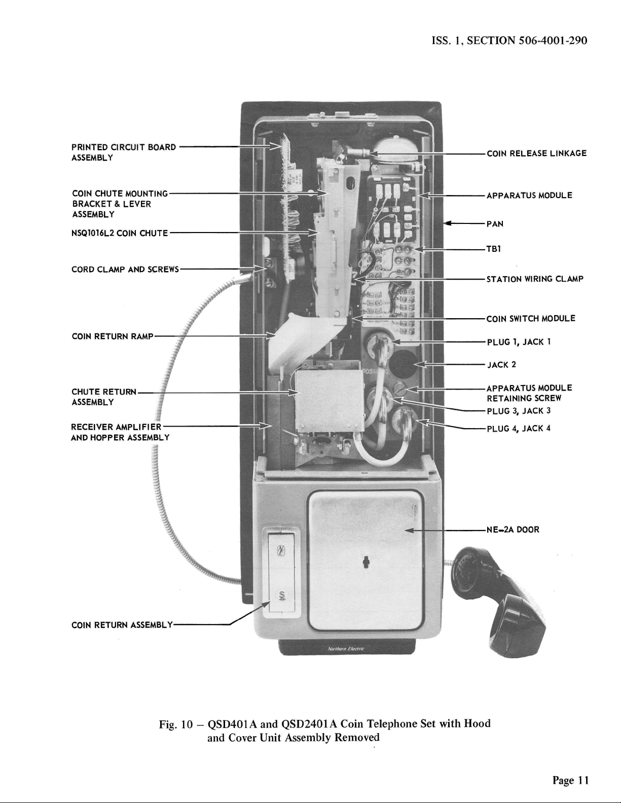
Remove plugs 1, 3, and 4 from jacks on apparatus module (Fig. 10).
Disconnect handset leads from terminals R, B, W, and Won terminal strip TB1.
Disconnect station wiring leads from terminals T, R, and G on TB1.
Completely loosen captive screw located between _jacks2 and 4.
Pull lower end of module forward, approximately 1/4 inch and lower module until upper
end of module mounting bracket is clear of locating slots in housing mounting plate.
Pull module forward carefully to avoid unnecessary interference with chute mounting
bracket or coin relay.
8 Replace the apparatus module by reversing the above procedure.
6. OPERATION CHECKS
6.01 On completion of the installation, perform
the operational checks outlined in Charts 3,
4, and 5.
CHART 3 - CALL ORIGINATION TEST
STEP PROCEDURE
1 Remove the handset from the hook.
2 Dial test number for chargeable local call.
3 Called party answers.
4 Calling party responds.
5 Calling party deposits coins to a total
value less than the initial rate charge.
Page 10
VERIFICATION
Dial tone heard in handset.
Operation of dial breaks dial tone.
Called party cannot hear calling party.
Called party cannot hear calling party.
TCI Library https://www.telephonecollectors.info/
PRINTED CIRCUIT BOARD-----
ASSEMBLY
COINCHUTEMOUNTING-----
BRACKET& LEVER
ASSEMBLY
NSQ1016L2COIN CHUTE-----__,;:;;:
CHUTERETURN--'-------
ASSEMBLY
RECEIVERAMPLIFIER------
AND HOPPERASSEMBLY
I
~
i
1
\
~
\
~
COIN RETURNASSEMBLY
1
ISS. 1, SECTION 506-4001-290
---APPARATUS MODULE
---TBl
~~~~..:;;_~~I~---STATIONWIRINGCLAMP
'"==,=~~~~---COIN SWITCHMODULE
---PLUG 1, JACK 1
---JACK2
---APPARATUS MODULE
RETAININGSCREW
PLUG 3, JACK 3
PLUG 4, JACK 4
Fig. 10 - QSD401A and QSD2401A Coin Telephone Set with Hood
and Cover Unit Assembly Removed
Page 11

TCI Library https://www.telephonecollectors.info/
SECTION 506-4001-290
CHART 3 (Cont) - CALL ORIGINATION TEST
STEP PROCEDURE VERIFICATION
6 Calling party deposits additional coins Called party can hear calling party and
to a total value equal to or exceeding normal conversation is possible.
the initial rate charge.
7 Restore handset.
CHART 4 - TRANSMISSION, COIN IDENTIFICATION TONE, AND RINGBACK TESTS
STEP PROCEDURE
1 Complete call to operator or test center.
2 Request identifcation of 5-cent, 10-cent,
and 25-cent coin deposits.
3 Request ringback from operator or test
center and restore handset.
4 Answer ringback call.
5 Restore handset.
CHART 5 -COIN HANDLING TESTS
STEP
I
2
Page 12
12 Pages
PROCEDURE
Deposit 5-cent, I0-cent and 25-cent coins.
Deposit I-cent coin.
VERIFICATION
Operator or test center answers and con-
firms that voice levels are satisfactory.
Operator or test center correctly identifies
coin deposits and confirms that coin signal
levels are satisfactory.
Ringback is received.
VERIFICATION
Coins pass through the coin chute, switch
module and hopper into the cash compart-
ment.
Coin is rejected and returned through
the coin return.
This manual suits for next models
2
Other NORTHERN ELECTRIC Telephone manuals


