nosstec 8264 User manual

Bending Roll Machine 8264
Operating instructiOns

8264 English, rev 3 3
Table of conTenTs
Main components ............................................................4
Operation .....................................................................5
Safety..........................................................................7
Service and maintenance .................................................. 12
Lubrication / Grease chart ................................................. 13
Technical data .............................................................. 14
Machine plates and stickers ............................................... 15
Dismantling of bending roll machine ..................................... 16
Declaration of conformity.................................................. 22
Contact information................................................. See back
Note: We reserve the right to alter specifications without prior notice.
For copyright reasons all reproduction and copying of the texts, tables and illustrations within this manual is
prohibited without written permission from Nosstec AB.

Operating instructiOns 8264
42018-09-12
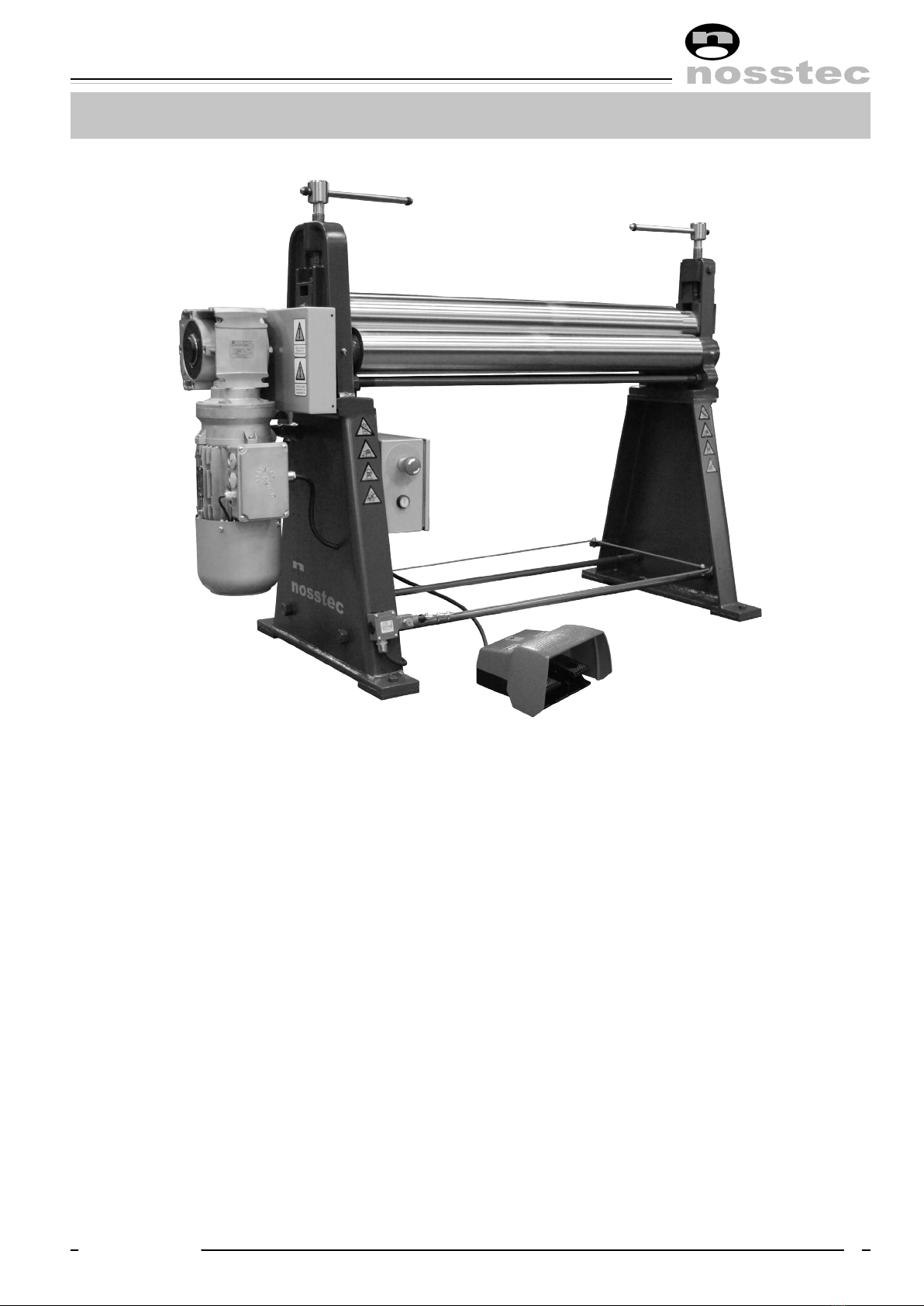
Stand, power
operated side
Motor with
gear box
Emergency
stop
Safety equipment
Bending roll Lower roll
Stand,
drop end
Drop end
Main coMponenTs
Front side
Foot switch
Disclaimer: The machine pictured on this page is not necessarily representative of the actual product
as delivered. Differences in sizes, options and/or accessories may or may not be pictured here.
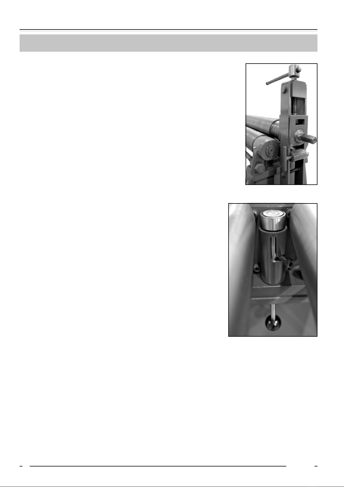
Set screw,
bending roll
Cone bending device

8264 English, rev 3 5
operaTion
Prebending
In order to obtain a symmetrically round shape, it is necessary to prebend the front as well as the rear
edge of the workpiece. This prebending can be carried out by means of suitable equipment e.g. a
press brake or manual folding machine. This operation can not be performed with a 8264 bending roll
machine.
Bending
This machine shall be used for bending sheets to a round shape. Also cylinders with conical shape can be
bent if the machine is equipped with cone bending device.
At the maximum operating length and the maximum sheet thickness tubes down to about 1,5 times the
diameter of the bending roll can be formed and for thinner sheets down to about 1,2 times the diameter
of the roll.
When bending steel sheet or stainless steel the maximum thickness capacity of the machine will be
reduced to about ⁄ compared to mild carbon steel sheet.
Bending operation:
The bending roll is screwed up so that the workpiece can be introduced between the bending roll
and lower rolls. After having centered the workpiece in the machine, the bending roll is screwed down
towards the workpiece so that a bend appears. How much the bending roll must be screwed down
depends partly on the thickness of the material and partly on the final diameter.
Generally the sheet must be run through the machine several times in order to obtain the desired shape.
When the workpiece has been introduced between the rolls, the machine can be started by means
of the pedal switch. The workpiece should then be run through the machine until it nearly leaves the
lower roll. After this the bending roll is screwed down somewhat and the procedure is repeated but
in the opposite direction by means of the pedal switch. Continue to run the workpiece forwards and
backwards at the same time as the bending roll is screwed down, until the workpiece has obtained the
desired shape.
In order to get a better cylinder, the workpiece can be run through the machine some extra times, either
direct after the rolling or after the joint has been welded and emery ground.
Operating instructiOns 8264
62018-09-12
operaTion
Removal of workpiece
The finished workpiece is removed from the machine as follows:
• Loosen the set screws of the bending roll so that the bending roll is
released from the workpiece.
• Remove the locking device of the clamp.
• Introduce a flat bar or similar between the bending and lower rolls a
couple of centimeters from the drive side.
• Turn the set screw on the drive side down so that the bending roll
hangs freely when the clamp is pulled down.
• Go over to the other side of the machine and adjust the set screw
until the clamp can easily be pulled down.
• Pull down the clamp and remove the workpiece.
• Raise the clamp and mount the locking device.
Cone bending
In order to be able to make cones, the machine must be equipped
with a cone bending device.
The cones are made as follows:
• Raise the cone bending device so that it rests on the bending roll
(see figure).
• Introduce the workpiece so that its rear end is parallel to the rear
lower roll and the small radius points at the cone bending device.
• Screw down the bending roll on the cone bending side so that a
bend appears (check that there is enough room for the material to
move).
• Start the bending process and let the sheet skid against the cone
bending device at the same time as it is fed through the machine
and bent.
• Screw down the bending roll somewhat. Bend again and continue
until the cone has obtained the desired form.
8264 English, rev 3 7
safeTy
General
This bending roll machine is designed with a view to eliminating personal injuries provided that the in-
structions in this manual are being followed.
Only authorized and trained staff is allowed to use the machine. Read the whole instruction manual and
make sure that you understand the contents before the machine is taken into use. It is important that
you read the safety instructions below.
Safety instructions in connection with the installation
The machine must be bolted to the floor with 4 pcs expansion shell bolts diameter 16 mm.
Electrical installation of the machine must be carried out by authorized staff.
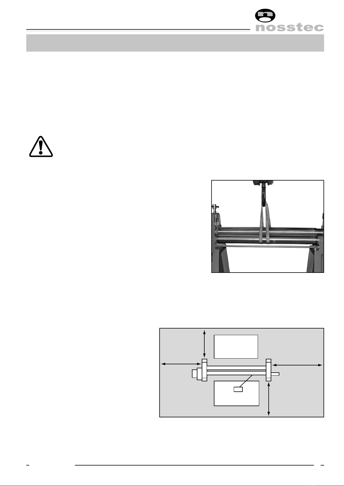
Lifting instructions
This machine must be lifted by truck as long as it is packed
in a crate or a wooden case. When lifting it from the pack-
ing to the permanent working site an approved lifting de-
vice type travelling crane must be used. Instructions for lift-
ing be means of travelling crane:
1. Check that the top roll is in the locked position.
2. Set lower and bending roll in upper position.
3. Put a lifting sling around the rolls as per figure.
4. Lift carefully at the same time as you check that the
rolls are pressed together.
Regarding weights: see technical data
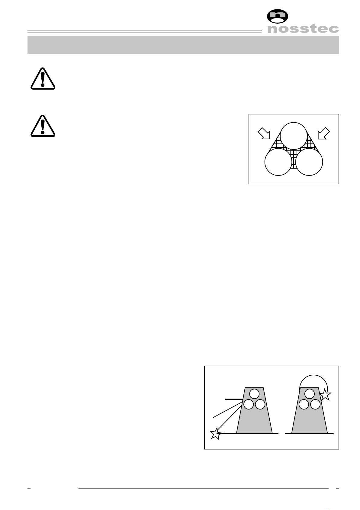
Dangerous area
The dangerous area of the machine is
described in the figure.
This area shall in an appropriate way be
marked in the floor.
A person staying in the dangerous area
will henceforth be called “exposed per-
son” and the user of the machine the
“operator”.
Operator,
prebending
Operator
1,5 m
1,5 m 1,5 m
1,5 m
Operating instructiOns 8264
82018-09-12
safeTy
Application
Never use the machine for material which is outside the capacity range of the machine. Check
the machine plate and the section “Technical data”.
Before the machine is operated the following steps must be taken:
Check that all safety devices function and that they are not damaged. Also check that moveable parts
are not exposed to obstacles e.g. owing to incorrectly mounted guards or parts. Broken parts or safety
components must be changed by authorized staff. Contact Nosstec in case spare parts are needed. The
machine has a 24 month applicable warranty from date of delivery.
Check that the environment around the machine is suitable.
• Do not expose the machine to rain.
• Do not use the machine in wet or damp premises.
• Check that the lighting of the premises is satisfactory.
• The floor must be clean, dry and free from oil and grease spots.
• Never use easily inflammable material close to the machine.
• Dirty working sites increase the risk of accidents.
Position of top roll
The top roll must never be in the swung-out position when the machine is in operation.
Avoid unstable working positions
Check that the operator always has a secure and stable working position. When prebending the opera-
tor must stand on the reverse side of the machine.
Do not keep tools on the machine
Remove all tools from the machine before it is operated.
All repairs must be carried out by authorized staff
The machine and its electrical equipment has been made according to valid safety rules. All
repairs must be carried out by trained and qualified staff. Only original spares must be used.
Note: If the repairs also involve dismantling of the machine, this must be carried out
according to the enclosed dismantling instruction. This instruction must not be kept
together with the machine.
8264 English, rev 3 9
safeTy
Cut the power
Cut the current before touching live parts. This is done either by disconnecting the main
switch of the machine or by disconnecting the voltage of the electrical cabinet.
Note: Do not put the main switch or the safety switch of the machine out of operation.
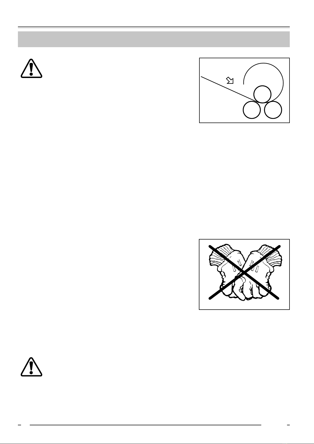
Danger zone
In connection with production work check that no part
of the body comes too close to the infeed side of the
clamping rolls of the machine (see figure).
Note: The infeed side may vary owing to the direction
of rotation of the rolls.
Keep the instruction manual of the machine in a safe place.
The instruction manual contains important information that besides the safety information also give
important information regarding operation, service, maintenance etc.
Modification of the machine
All conversion, modification or change of this machine is strictly forbidden with the exception of
• Original spare parts
• Optional equipment supplied by the manufacturer.
Airborne noise
The following noise level has been measured at the operator’s place:
Equivalent noise level Leq, idle running 66 dB(A)
Equivalent noise level Leq, operation 68 dB(A)
Falling workpieces
Be careful when working with heavy workpieces so
that they do not fall down by mistake when the grip
loosens between the bending and lower rolls (see fi-
gure). If necessary use a support table, travelling cra-
ne or some other lifting device.
Operating instructiOns 8264
10 2018-09-12
safeTy
Pinching risk of the workpiece
Note that there is a pinching risk between the ends
of the workpiece, see figure.
Emergency stop
This machine is equipped with two emergency stop functions, i.e. one emergency stop on the electrical
cabinet and one emergency wire running around the machine at foot height. This together with the fact
that the machine is equipped with brake motor enables the machine to stop instantaneously in case of
injury or risk of injury no matter where you are around the machine.
Service and maintenance
Before service and maintenance are carried out on the machine you must have had instructions from
your foreman. You must also read and understand this instruction manual. Disconnect the main switch
before the service job begins. If the machine must be dismantled, completely or partly, contact your
foreman.
Protective clothing
Important! Never use gloves when bending, as this consider-
ably increases the risk of getting pinched between the rolls.
For other handling of the workpieces use gloves. The operator
must not carry belts, rings or necklaces.
Working shoes with steel inserts must be used.
Loose hanging clothes must not be used.
If the operator has long hair, this must not hang loose.
Deburring of the workpiece
Burrs and sharp edges must be removed from the workpiece before bending.
Jamming
If for some reason the machine stops while
bending a workpiece, proceed as follows:
• Crank down the bottom roll and possibly also the bending roll.
• Remove the workpiece. Identify the trouble reason. If the motor protection is released,
wait for some minutes before it is reset. The machine is then ready for use again.
• If the trouble is mechanical or electrical: Cut the current and contact the supervisor.
Pinching risk

8264 English, rev 3 11
safeTy
Regular checking
Daily check the function of the foot switch as well as the condition of the electric cable of the foot switch.
Also check that the emergency stop works. Carry also out the regular service, which is described in the
chapter Service and Maintenance in the instruction manual.
Safety in general
The chapters describing the safety devices are based on the assumption that the machine is used in the
manner described in this instruction manual, that the operator has got the necessary information regard-
ing the safety of the machine as well as the special risks involved with this type of machine.
If the machine is not used in the proper way, the manufacturer cannot be held responsible for personal
injuries or material damages, which may be the result. Also check the following:
• Take all necessary safety precautions when loading, setting, changing spare parts, cleaning, repairing
and servicing so that the exposed person cannot start the machine.
• Do not disconnect the safety devices of the machine.
• Do not remove any part of the machine belonging to the safety devices.
• Always check that all safety devices have been remounted after repair work etc.

Operating instructiOns 8264
12 2018-09-12
service and MainTenance
Installation
The machine must be placed on firm ground e.g. cemented floor. The ground must be level in order to
avoid tensions in the machine when fixing it to the floor.
Check that the motor is branched to the right voltage. Also check the direction of rotation. Plates with
“Forward” and “Reverse” are mounted on the protection cover of the foot switch.
If the machine is equipped with motor powered setting of the bending roll and/or the lower roll also
check the voltage and oil level here.
Maintenance
The machine is delivered with greased bearings for about 200 hours’ continuous duty. After this period it
should be lubricated with ball bearing grease of good quality, e.g. Esso Multi purpose grease H or equiv-
alent. All rolls and worm gears are mounted on needle and ball bearings and therefore recommended
grease should be used. Guides for the roll bearing box as well as sleeves for the bending roll and cone
bending device to be lubricated when required. Grease lubs, see grease chart.
The gearbox is lifetime lubricated and doesn’t need any regular inspection. Should there be any leakage,
please check oil level and refill if necessary.
Daily check
• Brake function of the motor
• All emergency stop functions
8264 English, rev 3 13
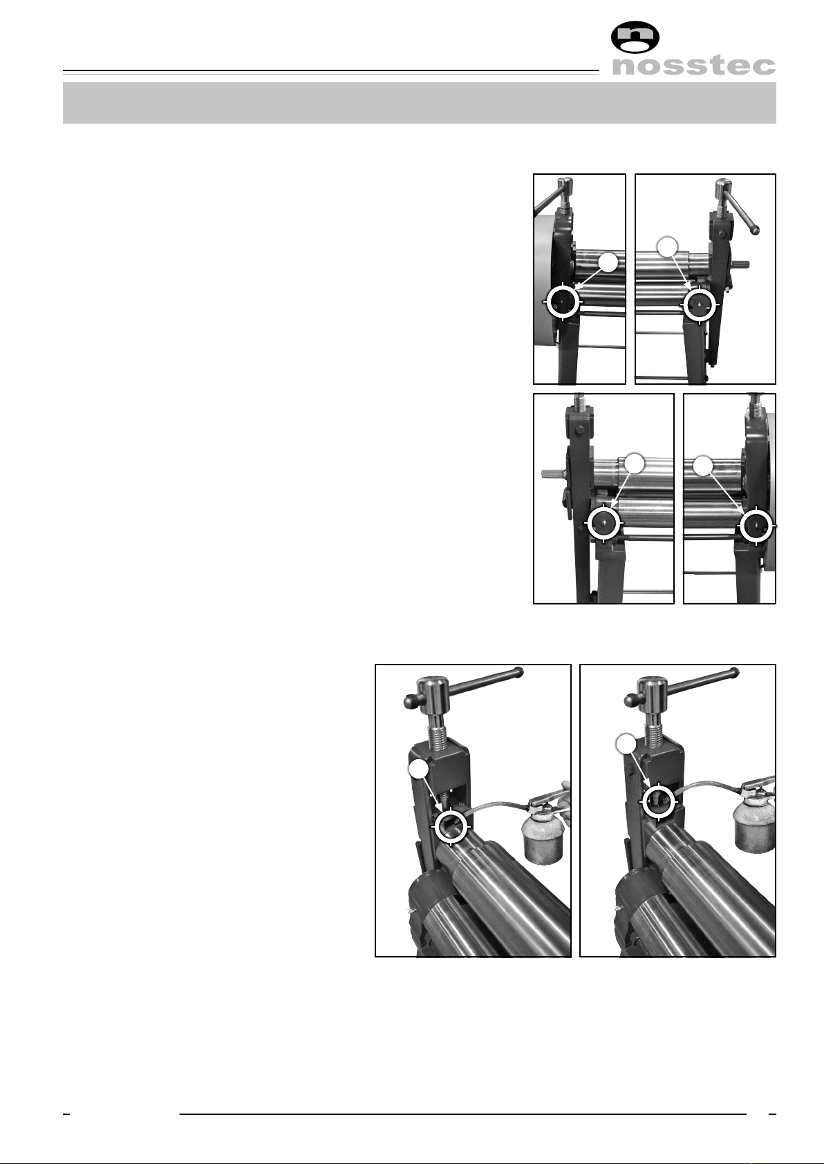
lubricaTion / Grease charT
Lubrication points
There are in total 4 lubrication points:
1. Front left side, 1 points.
2. Front right side, 1 point.
3. Rear left side, 1 point.
4. Rear right side, 1 points.
See images for the lubrication
points locations.
Oil points
There are in total 4 locations:
5. Left and right bearing
housing, 2 locations.
6. Left and right set screw
thread, 2 locations.
3
2
6
7
1
4

Operating instructiOns 8264
14 2018-09-12
Technical daTa
Serial No ...............................................................................
Type .....................................................................................
Rolling speed ......................................................................... m/min
Max. sheet thickness (at 400 N/mm2).......................................... mm
Operating length .................................................................... mm
Total net weight ..................................................................... kg
Weight of rolls
Bending roll ....................................................................... kg/m
Lower rolls ......................................................................... kg/m
Total dimensions: length × width × height .................................. mm
Working height ...................................................................... mm
Motor rating .......................................................................... kW
Voltage ................................................................................. V
Feeding motor:
Brand .............................................................................
Type..............................................................................
..................................................................................... V
..................................................................................... kW
Diameter of bending roll .......................................................... mm
Diameter of lower rolls............................................................. mm
Optional equipment:
Cone bending equipment
Hardened and ground rolls
Adiprene-coated rolls
Deviation from the normal execution:

8264 English, rev 3 15
Machine plaTes and sTickers
REVERSE FORWARD
Blue background, white text Blue background, white text
MAIN SWITCH MUST BE
DISCONNECTED FOR ALL
TYPES OF SERVICE AND
MAINTENANCE
ONLY TRAINED STAFF
MAY HANDLE THIS
MACHINE
NEVER RUN THE MACHINE
WITH THE TOP ROLL IN
SWINg-OUT POSITION
White and yellow background,
black text
White and yellow background,
black text
White and yellow background,
black text
Yellow background,
black text
Yellow background,
black text
Yellow background,
black text
Yellow background,
black text
Nosstec AB
Järnvägsgatan 19
465 30 Nossebro
SWEDEN
Productionyear:
Type:
Capacity:
Weight:
Serial No:
Kg.
mm.
Current:
Voltage:
Phase:
Frequency:
Aluminium plate, blue anodized.

Operating instructiOns 8264
16 2018-09-12
disManTlinG of The Machine
This instruction is made in order to support trained staff when repairing with a view to minimizing the
risk of personal injuries and damage to the machine.
To enable dismantling of the machine in a safe way, the job must be carried out by at least two trained
mechanics.
This dismantling instruction must not be kept together with the machine. The proper holder is the su-
pervisor and/or service staff.
Procedure:
1. Loosen the bolts attaching the gear housing.
2. Pull the worm gear motor out of the worm gear box.
3. Loosen the bolts and remove the cover.
4. Remove the locking ring of the bending roll.
5. Open the drop end on the opposite drive side.
6. Pull the bending roll out of the bearing housing so that it rests on the lower rolls.
7. Place a lifting strap in the middle of the bending roll. Remove the roll and place it e.g. on a bench.
8. Pull off the roller gears from the lower rolls.
9. Lower the lifting strap around the lower rolls and fixate them by means of a strong flat iron between
the rolls.
10. Loosen the nuts on the in- and outside of the front part.
11. Release the front part.
12. Place a strong support under the detached roll ends (Note: not under the roll necks), and place the
lifting strap under the centre of gravity of one of the rolls. Pull the roll out of the frame, lift it down
and place it on e.g. a bench. Repeat this procedure with the other lower roll.
NOTE: Handle the loose parts carefully and check that all pieces removed also are mounted in their
right places, but in the reverse order.
5
6
11
10
1
3
7
4
10

8264 English, rev 3 17
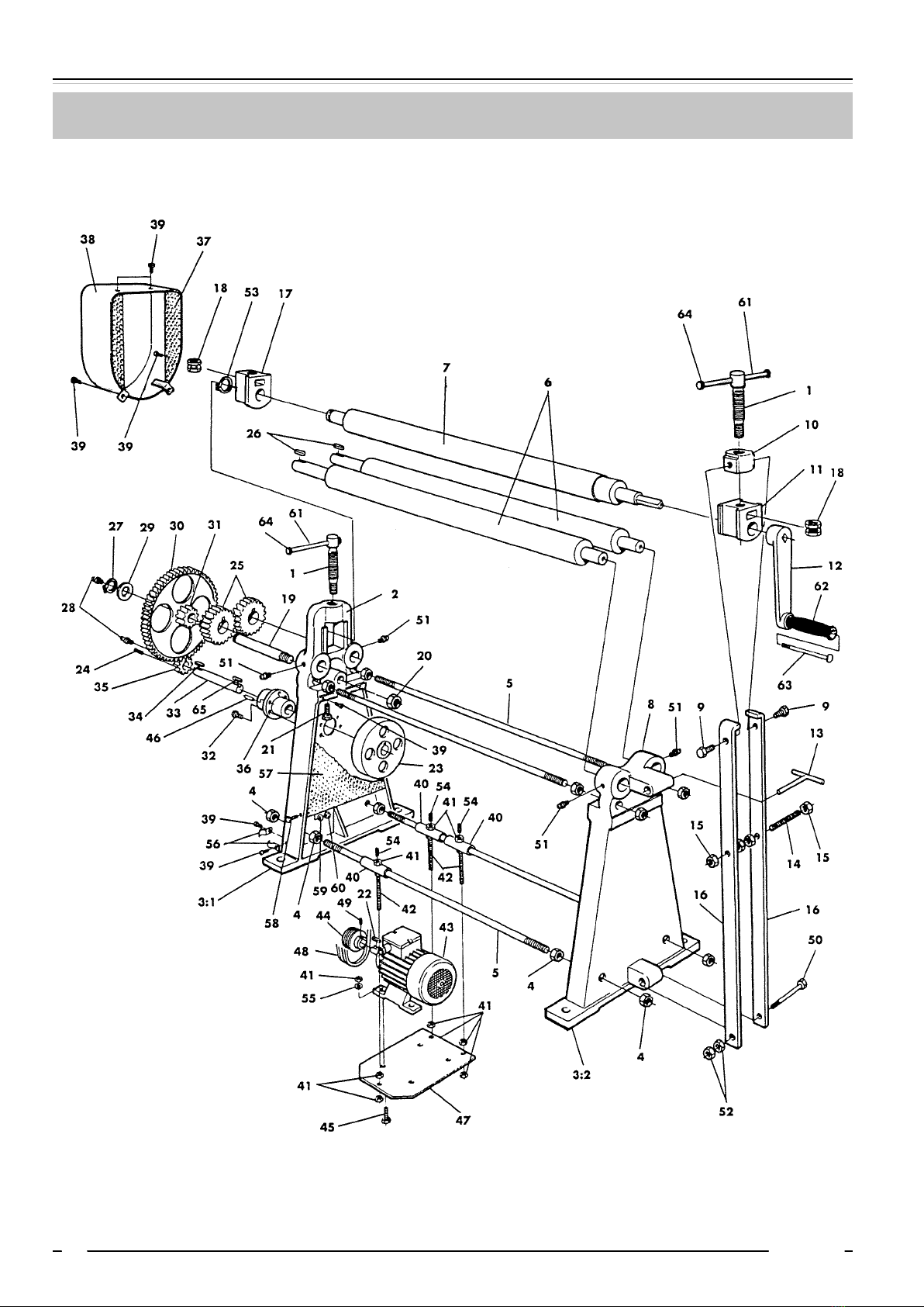
spare parTs, 80-90
Operating instructiOns 8264
18 2018-09-12
spare parTs, 90-100

8264 English, rev 3 19
spare parTs, 100-110

Operating instructiOns 8264
20 2018-09-12
spare parTs, 120-130
Table of contents
Other nosstec Cutter manuals


Popular Cutter manuals by other brands


Safety Speed Manufacturing
Safety Speed Manufacturing 60HA owner's manual

Laski
Laski FZ 500/27 operating instructions

Makita
Makita DCS553Z instruction manual

AL-KO
AL-KO GS 7,2 Li Translation of the original instructions for use

Fein
Fein Special Cutter FSC 1.6 Parts Breakdown

SPEWE
SPEWE 1900ML-30 04 Series manual


