nosstec 8266 User manual

Bending Roll Machine 8266
Operating instructiOns

8266 English, rev 8 3
Table of conTenTs
Main components ............................................................4
Operation .....................................................................5
Safety..........................................................................7
Service and maintenance .................................................. 12
Lubrication / Grease chart ................................................. 14
Technical data .............................................................. 15
Machine plates and stickers ............................................... 16
Dismantling of bending roll machine ..................................... 17
Spare parts, 80-90mm ..................................................... 18
Spare parts, 100-110-120mm............................................... 22
Spare parts, 130-140mm ................................................... 26
Declaration of conformity.................................................. 30
Contact information.................................................See back
Note: We reserve the right to alter specifications without prior notice.
For copyright reasons all reproduction and copying of the texts, tables and illustrations within this manual is
prohibited without written permission from Nosstec AB.

Operating instructiOns 8266
Foot switch
42013 - 0 6 -11
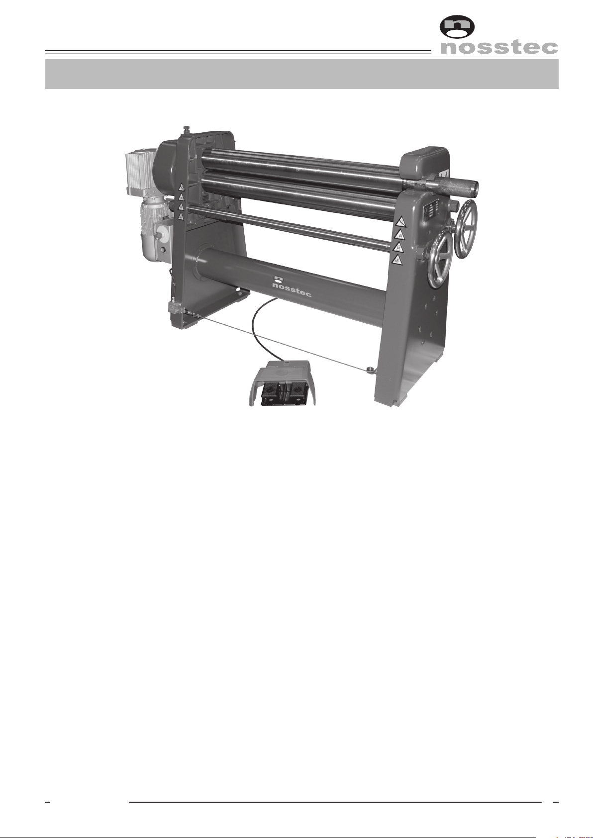
Back side
Stand, power
operated side
Emergency stop
Top roll
Lower roll
Safety equipment
Stand, slip collar
side
Handwheel for
lower roll
Handwheel
with counter
for bending roll
Pull-out sleeve for
top roll
Main coMponenTs
Front side
Disclaimer: The machine pictured on this page is not necessarily representative of the actual product
as delivered. Differences in sizes, options and/or accessories may or may not be pictured here.
Bending roll
Motor for
bending roll
Diagonal setting of
bending roll
Gear box
Motor for
lower roll
Brake motor
Worm gear

8266 English, rev 8 5
operaTion
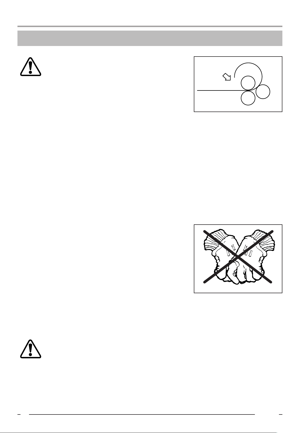
Prebending
In order to give the workpiece a
symmetrically round shape, it is
necessary to prebend the part of the
workpiece, which should be bent first.
This must be made from the back
of the machine and with the rolls
rotating in the opposite direction (see
picture 1 in the figure on the right).
Bending
Place the bending roll in the required position (see setting diagram below).
Introduce the prebent workpiece between the upper and lower rolls and use the bending roll as a back
gauge.
Turn the hand wheel of the lower roll so that the workpiece is clamped between the rolls. Bend the sheet
(check that the sheet runs above the bending roll as per picture 2 in the figure above).
Adjust the bending roll and repeat the operation until the workpiece has got the desired shape. Swing
out the top roll and remove the workpiece. Swing back the top roll into its initial position.
At the maximum operating length and the maximum sheet thickness tubes down to about 1,5 times the
diameter of the upper roll can be formed and for thinner sheets down to about 1,2 times the diameter of
the roll.
When bending steel sheet or stainless steel the maximum thickness capacity of the machine will be
reduced to about ⁄ compared to mild carbon steel sheet.
NOTE: If the machine is equipped with motor-powered setting of the bending roll check carefully that
the limit switches are correctly adjusted.
Radius of workpiece
Setting of bending roll = height adjustment
2
1
3
0 100 200 300 400 500
100
90
80
70
60
50
40
30
20
10
0
Setting diagram
Ex. Bending of a tube with dia. 300:
➀Look for the radius 150
➁Go to the setting curve
➂Read the total setting on the left hand scale
The result is dependent upon the material used (spring
back). Recommended number of settings 3-5.

Operating instructiOns 8266
62013 - 0 6 -11
operaTion
Cone (taper) bending
If the machine is equipped with cone bending
equipment, it is very important that such opera-
tions are carried out as follows:
1. Raise the trailing shoe so that it rests against
the lower roll of the machine. Place it in a
suitable position within the working range of
the machine (stop rings on both sides of the
shoe are loosened, the shoe is moved and
the stop rings are tightened again after the
adjustment). NOTE: Always try to work in the
middle of the machine.
2. Set the bending roll machine in its lowest
position, if the small diameter of the cone
is directed against the swing-out side of
the machine. Read the value shown on the
handwheel with dial register (this in order to
obtain parallelism when resetting the ben-
ding roll after finished bending).
3. Pull out the sleeve of the shaft coupling, raise
the bending roll by means of the handwheel.
The worm screw of the stand on the left-
hand side is now disconnected. The screw
in the stand on the right hand side is now
connected and the bending roll is raised to
the required position, dependent upon the
shape of the cone (the trailing shoe is now
placed close to the swing out side).
If the bending should be carried out with the
trailing shoe placed at the stand on the left
hand side, the bending roll must be raised
here and lowered at the right hand side.
4. The machine is now adjusted for the bending
of precut cone pieces (when cone bending
it is adviseable to prebend both ends of the
sheet).
5. When bending, check that there is always
room for the material to move in the
machine.
6. Adjust the lower roll with arbitrary pinching
force (not too hard setting). The sheet must
be able to move between the rolls.
7. Introduce the straight edge of the precut
workpiece between the rolls, with the small
radius turned against the head of the trailing
shoe. Start the machine by means of the
foot switch and let the sheet slide against
the trailing shoe at the same time as it is fed
forward and bent against the bending roll.
NOTE: When cone bending always run
the machine “Forward”. Check that the
bending is carried out as per requirement. If
adjustment of both sides of the bending roll
is necessary, the sleeve of the shaft coupling
must be connected so that both worm screws
of the machine are actuated. Do not forget to
check the setting of the dial register.
8. Run the workpiece through the machine,
then reset the bending roll. Now bend
once more and continue until the cone has
obtained the correct shape.
9. After cone bending reset the machine in its
initial position, so that ordinary cylinders can
be bent.
NOTE! Important when
setting the bending roll
diagonally
Do not set the bending roll diagonally so
much that it has a pinching effect against the
top roll in its raised highest position. This to
avoid overloading of the bending roll, as the
movement of the roll results in a cutting ef-
fect. At worst the top roll can break resulting
in severe injuries.
8266 English, rev 8 7
safeTy
General
This bending roll machine is designed with a view to eliminating personal injuries provided that the in-
structions in this manual are being followed.
Only authorized and trained staff is allowed to use the machine. Read the whole instruction manual and
make sure that you understand the contents before the machine is taken into use. It is important that
you read the safety instructions below.
Safety instructions in connection with the installation
The machine must be bolted to the floor with 4 pcs expansion shell bolts diameter 16 mm.
Electrical installation of the machine must be carried out by authorized staff.
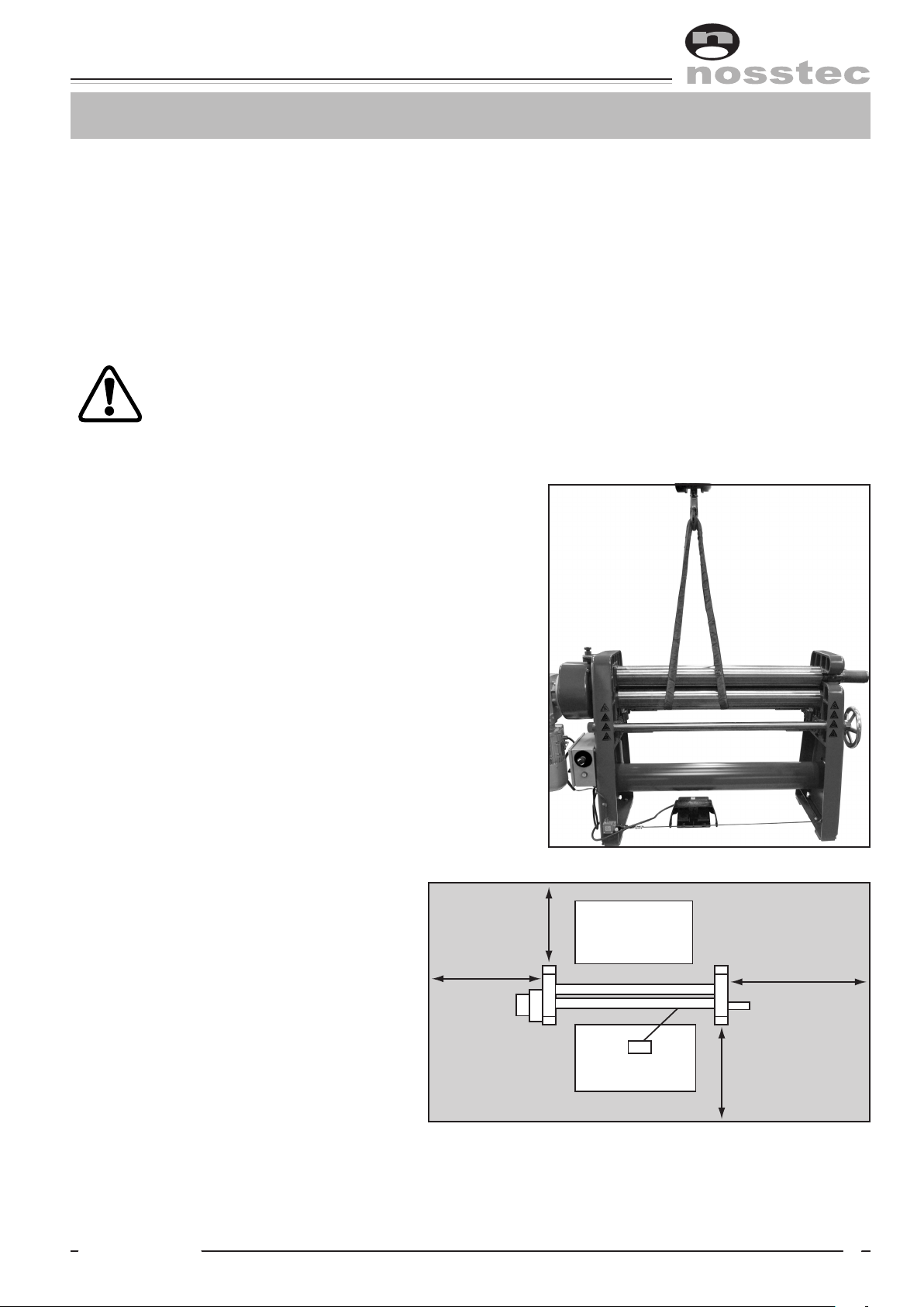
Lifting instructions
This machine must be lifted by truck as long as it is
packed in a crate or a wooden case. When lifting it
from the packing to the permanent working site an ap-
proved lifting device type travelling crane must be used.
Instructions for lifting be means of travelling crane:
1. Check that the top roll is in the locked position.
2. Set lower and bending roll in upper position.
3. Put a lifting sling around the rolls as per figure.
4. Lift carefully at the same time as you check that the
rolls are pressed together.
Regarding weights: see technical data
Dangerous area
The dangerous area of the machine is
described in the figure.
This area shall in an appropriate way be
marked in the floor.
A person staying in the dangerous area
will henceforth be called “exposed per-
son” and the user of the machine the
“operator”.
Operator,
prebending
Operator
1,5 m
1,5 m 1,5 m
1,5 m
Operating instructiOns 8266
82013 - 0 6 -11
safeTy
Application
Never use the machine for material which is outside the capacity range of the machine. Check
the machine plate and the section “Technical data”.
Before the machine is operated the following steps must be taken:
Check that all safety devices function and that they are not damaged. Also check that moveable parts
are not exposed to obstacles e.g. owing to incorrectly mounted guards or parts. Broken parts or safety
components must be changed by authorized staff. Contact Nosstec in case spare parts are needed. The
machine has a 24 month applicable warranty from date of delivery. The warranty is only applicable as
long as original spare parts are used.
Check that the environment around the machine is suitable.
• Do not expose the machine to rain.
• Do not use the machine in wet or damp premises.
• Check that the lighting of the premises is satisfactory.
• The floor must be clean, dry and free from oil and grease spots.
• Never use easily inflammable material close to the machine.
• Dirty working sites increase the risk of accidents.
Position of top roll
The top roll must never be in the swung-out position when the machine is in operation.
Avoid unstable working positions
Check that the operator always has a secure and stable working position. When prebending the operator
must stand on the reverse side of the machine.
Do not keep tools on the machine
Remove all tools from the machine before it is operated.
All repairs must be carried out by authorized staff
The machine and its electrical equipment has been made according to valid safety rules. All
repairs must be carried out by trained and qualified staff. Only original spares must be used.
Note: If the repairs also involve dismantling of the machine, this must be carried out
according to the enclosed dismantling instruction. This instruction must not be kept
together with the machine.

8266 English, rev 8 9
safeTy
Cut the power
Cut the current before touching live parts. This is done either by disconnecting the main
switch of the machine or by disconnecting the voltage of the electrical cabinet.
Note: Do not put the main switch or the safety switch of the machine out of operation.
Danger zone
In connection with production work check that no part
of the body comes too close to the infeed side of the
clamping rolls of the machine (see figure).
Note: The infeed side may vary owing to the direction
of rotation of the rolls.
Keep the instruction manual of the machine in a safe place.
The instruction manual contains important information that besides the safety information also give im-
portant information regarding operation, service, maintenance etc.
Modification of the machine
All conversion, modification or change of this machine is strictly forbidden with the exception of
• Original spare parts
• Optional equipment supplied by the manufacturer.
Airborne noise
The following noise level has been measured at the operator’s place:
Equivalent noise level Leq, idle running 62 dB(A)
Equivalent noise level Leq, operation 63 dB(A)
Falling workpieces
Be careful when working with heavy workpieces so
that they do not fall down by mistake when the grip
loosens between the upper and lower rolls (see figu-
re). If necessary use a support table, travelling crane
or some other lifting device.
Operating instructiOns 8266
10 2013 - 0 6 -11
safeTy
Pinching risk of the workpiece
Note that there is a pinching risk between the ends
of the workpiece, see figure.
Emergency stop
This machine is equipped with two emergency stop functions, i.e. one emergency stop on the electrical
cabinet and one emergency wire running around the machine at foot height. This together with the fact
that the machine is equipped with brake motor enables the machine to stop instantaneously in case of
injury or risk of injury no matter where you are around the machine.
Service and maintenance
Before service and maintenance are carried out on the machine you must have had instructions from
your foreman. You must also read and understand this instruction manual. Disconnect the main switch
before the service job begins. If the machine must be dismantled, completely or partly, contact your
foreman.
Protective clothing
Important! Never use gloves when bending, as this consider-
ably increases the risk of getting pinched between the rolls.
For other handling of the workpieces use gloves. The operator
must not carry belts, rings or necklaces.
Working shoes with steel inserts must be used.
Loose hanging clothes must not be used.
If the operator has long hair, this must not hang loose.
Deburring of the workpiece
Burrs and sharp edges must be removed from the workpiece before bending.
Jamming
If for some reason the machine stops while
bending a workpiece, proceed as follows:
• Crank down the bottom roll and possibly also the bending roll.
• Remove the workpiece. Identify the trouble reason. If the motor protection is released,
wait for some minutes before it is reset. The machine is then ready for use again.
• If the trouble is mechanical or electrical: Cut the current and contact the supervisor.
Pinching risk

8266 English, rev 8 11
safeTy
Regular checking
Daily check the function of the foot switch as well as the condition of the electric cable of the foot switch.
Also check that the emergency stop works. Carry also out the regular service, which is described in the
chapter Service and Maintenance in the instruction manual.
Safety in general
The chapters describing the safety devices are based on the assumption that the machine is used in the
manner described in this instruction manual, that the operator has got the necessary information regard-
ing the safety of the machine as well as the special risks involved with this type of machine.
If the machine is not used in the proper way, the manufacturer cannot be held responsible for personal
injuries or material damages, which may be the result. Also check the following:
• Take all necessary safety precautions when loading, setting, changing spare parts, cleaning, repairing
and servicing so that the exposed person cannot start the machine.
• Do not disconnect the safety devices of the machine.
• Do not remove any part of the machine belonging to the safety devices.
• Always check that all safety devices have been remounted after repair work etc.
Operating instructiOns 8266
12 2013 - 0 6 -11
service and MainTenance
Installation
The machine must be placed on firm ground e.g. cemented floor. The ground must be level in order to
avoid tensions in the machine when fixing it to the floor.
Check that the motor is branched to the right voltage. Also check the direction of rotation. Plates with
“Forward” and “Reverse” are mounted on the protection cover of the foot switch.
If the machine is equipped with motor powered setting of the bending roll and/or the lower roll also
check the voltage here.
Maintenance
The machine is delivered with greased bearings for about 200 hours’ continuous duty. After this period it
should be lubricated with ball bearing grease of good quality, e.g. Esso Multi purpose grease H or equiv-
alent. All rolls and worm gears are mounted on needle and ball bearings and therefore recommended
grease should be used. Guides for the roll bearing box as well as sleeves for the upper roll and cone
bending device to be lubricatd when required. Grease lubs, see grease chart.
The gearbox is lifetime lubricated and doesn’t need any regular inspection. Should there be any leakage,
please check oil level and refill if necessary.
Daily check
• Brake function of the motor
• All emergency stop functions
Parallelism of the rolls
Check that all rolls are parallel. If adjustment is neces-
sary this is carried out on the right hand stand as fol-
lows:
• Loosen the stop screw (1) on the bearing housing
• Turn the screw (2) by means of a hexagon wrench.
The sleeve is placed at the free end of the screw
and turned either to the right or the left until the
right position of the roll is obtained. When the rolls
are parallel, lock the stop screw (1).
1
2

8266 English, rev 8 13
service and MainTenance
Adjustment of the safety clutch for the power operated bending roll
After some time the bending roll may tend to skip. Adjustment of
the safety clutch is carried out as follows:
• Remove the protection cover.
• Loosen the two stop screws on the clutch nut.
• Tighten the clutch nut about 1/4 revolution (max. 120 Nm).
• Lock the stop screws and mount the protection cover.
Accessories
To facilitate the above service measures the following accessories
are delivered together with the machine:
• 1 set hexagon wrenches

Operating instructiOns 8266
14 2013 - 0 6 -11
lubricaTion / Grease charT
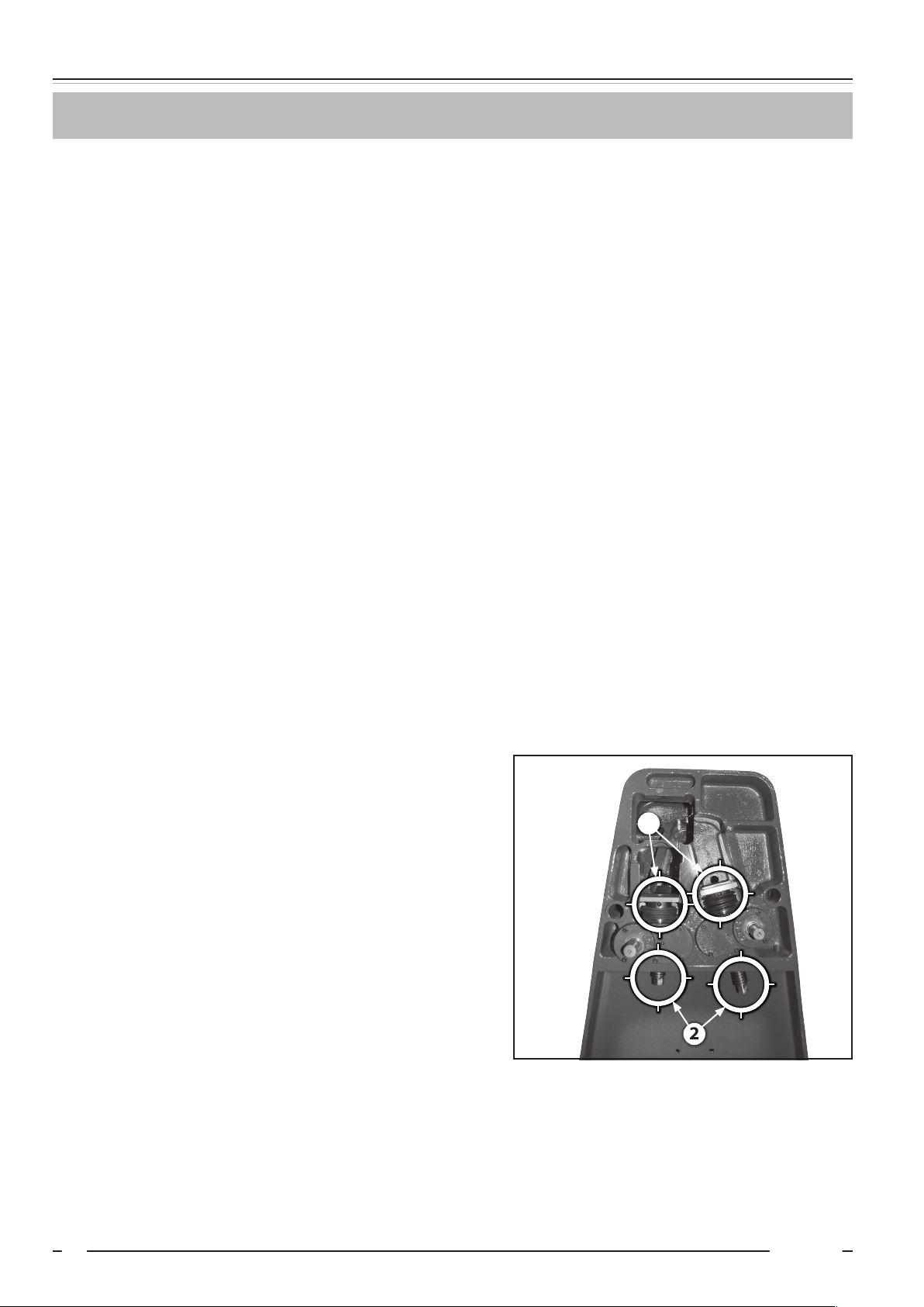
Lubrication points
There are in total 11 lubrication points:
1. Removable socket top roll.
2. Rear bearing top roll.
3. Gear wheel, gear box (lubricate frequently).
4. Rear and front bearing, intermediate gear, gear box.
5. Bearing box, bending roll left and right.
6. Worm gears bottom and bending rolls, left and right.
See images for locations of the lubrication points.
1
2
55
3
4
6

8266 English, rev 8 15
Technical daTa
Serial No ...............................................................................
Type .....................................................................................
Rolling speed ......................................................................... m/min
Max. sheet thickness (at 400 N/mm2).......................................... mm
Operating length .................................................................... mm
Total net weight ..................................................................... kg
Weight of rolls........................................................................ kg/m
Total dimensions: length × width × height .................................. mm
Working height ...................................................................... mm
Motor rating .......................................................................... kW
Voltage ................................................................................. V
Feeding motor:
Brand .............................................................................
Type..............................................................................
..................................................................................... V
..................................................................................... kW
Motor bending roll:
Brand .............................................................................
Type..............................................................................
..................................................................................... V
..................................................................................... kW
Motor lower rolls:
Brand .............................................................................
Type..............................................................................
..................................................................................... V
..................................................................................... Kw
Diameter of rolls ..................................................................... mm
Optional equipment:
Cone bending device
Trailing shoe
Diagonal setting of lower roll
Powered setting of bending roll
Powered setting of lower roll
Powered setting of bending roll, portable control
Powered setting of lower roll, portable control
Digital read-out of the bending roll
Digital read-out of the lower roll
Frequency inverter
Hardened and ground rolls
Adiprene-coated rolls
Handwheel with dial register
Stand for portable control
Deviation from the normal execution:

Operating instructiOns 8266
16 2013 - 0 6 -11
Machine plaTes and sTickers
Nosstec AB
Järnvägsgatan 19
465 30 Nossebro
SWEDEN
Productionyear:
Type:
Capacity:
Weight:
Serial No:
kg
mm
Current:
Voltage:
Phase:
Frequency:
Aluminium plate, blue anodized.
REVERSE FORWARD
Blue background, white text Blue background, white text
MAIN SWITCH MUST BE
DISCONNECTED FOR ALL
TYPES OF SERVICE AND
MAINTENANCE
O N LY T R A I N E D
STAFF MAY HANDLE
THIS MACHINE
NEVER RUN THE MACHINE
WITH THE TOP ROLL IN
SWINg-OUT POSITION
White and yellow background,
black text
White and yellow background,
black text
White and yellow background,
black text
Yellow background,
black text
Yellow background,
black text
Yellow background,
black text
Yellow background,
black text
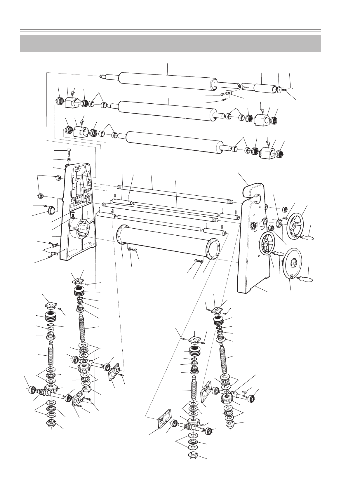
8266 English, rev 8 17
disManTlinG of bendinG roll Machine
This instruction is made in order to support trained staff when repairing with a view to minimizing the
risk of personal injuries and damage to the machine.
To enable dismantling of the machine in a safe way, the job must be carried out by at least two trained
mechanics.
This dismantling instruction must not be kept together with the machine. The proper holder is the su-
pervisor and/or service staff.
Procedure:
1. Secure the motor and worm gear with a lifting sling hanging from a travelling crane.
2. Loosen the bolts/nuts A and release the motor package.
3. Loosen the screws B and remove the cover C.
4. Loosen the shaft nut/screw D.
5. Dismount the gear wheel E (2 pcs).
6. Secure the top roll with a lifting sling and a travelling crane. Swing out the top roll and pull it out of
the stand.
7. Loosen the tube bar F on the right hand side of the machine by loosening the 6 screws G.
8. Loosen the 2 nuts H on the outside of the right hand stand.
9. Knock out the pin I of each socket J on the right hand side of the machine.
10. Secure the lower and bending rolls by means of a lifting sling and a travelling crane.
11. Release the right hand stand K.
12. Pull out the lower and bending rolls from the left hand stand L.
NOTE: Be careful with the loose parts and check that all parts removed also are mounted in their
right places, but in reverse order.
The letters in the above text refer to numbered machine components in the enclosed sketch drawing.
The part numbers valid for your machine are listed below. The number of your machine is found at the
top of the first page of the sketch drawings.
POS
TYPE A B C D E F G H I J K L
80/90 88 67 4 47 38
48 24 74 75 65 31 1 2
100/110/120 67 63 46 43 41:1
41:2 73 35 59 38 39 3 11
130/140 90 72 8 92 33 52 65 75 81 27 1 2
Operating instructiOns 8266
18 2013 - 0 6 -11
spare parTs, 80-90
57 8:1 81 57 58
25
26
27
64
70
49
50 79
58 57
81
8:2 57
57 781
57 58
58 57 81 757
51
76
2
75
60
43
37
73
6
93
83
93
31 65 23
45
1
42 75
60 86
85
75
84
85
85
87*
6
39:2
80
74
24
74
80
39:1
91
29:1
71
62
63
34
32
12
52
14 61
64
21
53
61
13
53
53
10
33
61
52
36
66
21
53
33
52
11
52
61
9
32
34
62
30:1
71
63 72 30:2 72
62
63
34
32
18
52
19
21 61 20
52
33
53
61
77
53
61
21
53
33
52
16
61
77
52
17
15
32
34
63
62
72
91
29:2
72
69

8266 English, rev 8 19
spare parTs, 80-90
88 89 90
82 35
78
4
47 40 38
44 54 55
368 64
46 81
54 55
5
65
93
92
48
89
67
59
59
28
56
41 56
77
77
64

Operating instructiOns 8266
20 2013 - 0 6 -11
spare parTs, 80-90
Svenska English Deutsch Francais
11Gavel utsvängbar sida Stand remov. side Gestell ausschwenkb. seite Bâti côté pivotant
21Gavel transmissionssida Stand trans. side Gestell trans.seite Bâti côté de
31Främre hushalva Front part bearing housing Vorderteil Lagergehäuse Front boite de palier
41Bakre hushalva Rear part Hinterteil Côté de derrière
5 1 Lagerhusinfästning Bearing housing bracket Lagergehäsebefästigung Fixation de boîte de palier
62Gavel underdel Stand upper part Ständer unterteil Bâti partie inférieure
7 2 Lagerhus Bearing housing Lagergehäuse Boîte de palier
8:1 1 Lagerhus Bearing housing Lagergehäuse Boîte de palier
8:2 1 Lagerhus Bearing housing Lagergehäuse Boîte de palier
9 1 Trapetsskruv Trapezoid screw Trapetzschraube Vis trapézoidal
10 1 Snäckhjul Worm gear wheel Schneckenrad Roue-vis
11 1 Snäckskruv Worm screw Schneckenschraube Vis sans fin
12 1 Trapetsskruv Trapezoid screw Trapetzschraube Vis trapézoidal
13 1 Snäckhjul Worm gear wheel Schneckenrad Roue-vis
14 1 Snäckskruv Worm screw Schneckenschraube Vis sans fin
15 1 Trapetsskruv Trapezoid screw Trapetzschraube Vis trapézoidal
16 1 Snäckhjul Worm gear wheel Schneckenrad Roue-vis
17 1 Snäckskruv Worm screw Schneckenschraube Vis sans fin
18 1 Trapetsskruv Trapezoid screw Trapetzschraube Vis trapézoidal
19 1 Snäckhjul Worm gear wheel Schneckenrad Roue-vis
20 1 Snäckskruv Worm screw Schneckenschraube Vis sans fin
21 4 Lagerlock Bearing cover Lagerdeckel Couvercle de palier
22 1 Hylsa Sleeve Hülse Douille
23 2 Stag Bar Stütze Support
24 1 Rörstag Tubular bar Rohrstütze Support tubulaire
25 1 Övervals Topp roll Oberrolle Rouleau supérieur
26 1 Undervals Lower roll Unterrolle Rouleau inférieur
27 1 Böjvals Bending roll Biegerolle Rouleau arriére
28 1 Kugghjul Gear Zahnrad Roue dentée
29:1 1 Lagerhusfäste Bearing housing bracket Gehäuseträger Serrage du carter de pali.
29:2 1 Lagerhusfäste Bearing housing bracket Gehäuseträger Serrage du carter de pali.
30:1 1 Lagerhusfäste Bearing housing bracket Gehäuseträger Serrage du carter de pali.
30:2 1 Lagerhusfäste Bearing housing bracket Gehäuseträger Serrage du carter de pali.
31 4 Hylsa Sleeve Hülse Douille
32 4 Styrhylsa Guide bushing Führungsbuchse Douille conductrice
33 4 Styrhylsa Guide bushing Führungsbuchse Douille conductrice
34 4 Krage Collar Kragen Collet
35 1 Kugghjul Gear Zahnrad Roue dentée
36 16 Skruv Screw Schraube Vis
37 4 Bricka Washer Teller Rondelle
38 1 Kugghjul Gear Zahnrad Roue dentée
39:1 1 Fläns Flange Flansch Bride
39:2 1 Fläns Flange Flansch Bride
40 1 Ändbricka End washer Endscheibe Disque
41 1 Distans Washer Unterlagsscheibe Rondelle
42 2 Tätningslock Tightening cover Dichtungsscheibe Rondelle jointe
43 2 Tätningslock Tightening cover Dichtungsscheibe Rondelle jointe
44 1 Distans Washer Unterlagsscheibe Rondelle
45 2 Axel Shaft Welle Axe
46 2 Skruv Screw Schraube Vis
47 1 Skruv Screw Schraube Vis
48 1 Kugghjul Gear Zahnrad Roue dentée
49 1 Styrning Guide Führung Guide
50 1 Ändbricka End washer Endscheibe Disque
51 1 Skruv Screw Schraube Vis
52 16 Löpbricka Washer Scheibe Rondelle
53 8 Nålkrans Needle ring Nadelring Bague
542Kombinerat nållager Comb. needle bearing Komb. Nadellager Palier à aiguilles comb.
55 2 Motbricka Counter-washer Gegenscheibe Rondelle
56 2 Innerring Inner ring Innenring Bague intérieur
Table of contents
Other nosstec Cutter manuals


