TESTING
Before testing, notify the proper authorities that the system is undergoing
maintenance, and will temporarily be out of
service. Disable the system to prevent unwanted alarms.
All sensors must be tested after installation and periodically thereafter. Testing
methods must satisfy the Authority Having
Jurisdiction (AHJ). Sensors offer maximum performance when tested and
maintained in compliance with NFPA 72.
Test the sensor as follows:
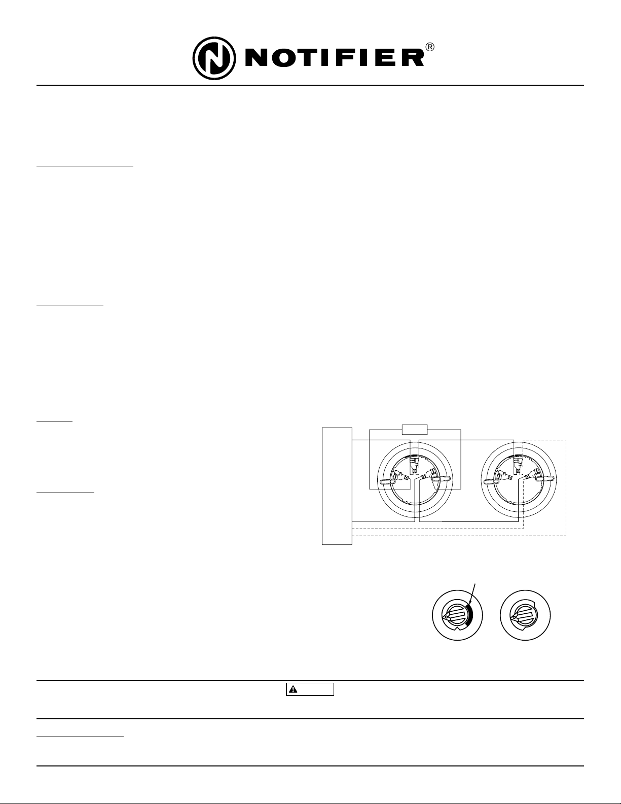
A. Functional: Magnet Test (P/N M02-04-01 or M02-09-00)
This sensor can be functionally tested with a test magnet. The test magnet
electronically simulates smoke in the sensing chamber, testing the sensor
electronics and connections to the control panel.
1. Hold the test magnet in the magnet test area as shown in Figure 3.
2. The sensor should alarm the panel.
Two LEDs on the sensor are controlled by the panel to indicate sensor sta-
tus. Coded signals, transmitted from the panel, can cause the LEDs to blink,
latch on, or latch off. Refer to the control panel technical documentation for
sensor LED status operation and expected delay to alarm.
B. Smoke Entry: Aerosol Generator (Gemini 501)
The GEMINI model 501 aerosol generator can be used for smoke entry
testing. Set the generator to represent 4%/ft to 5%/ft obscuration as
described in the GEMINI 501 manual. Using the bowl shaped applicator,
apply aerosol until the panel alarms.
A sensor that fails any of these tests should be cleaned as described under
CLEANING, and retested. If the sensor fails after cleaning, it must be replaced.
When testing is complete, restore the system to normal operation and notify the
proper authorities that the system is back in operation.
CLEANING
Before removing the detector, notify the proper authorities that the smoke
detector system is undergoing maintenance and will be temporarily out of
service. Disable the zone or system undergoing maintenance to prevent
unwanted alarms.
1. Remove the sensor to be cleaned from the system.
2. Remove the sensor cover. Press firmly on each of the four removal tabs that
hold the cover in place.
3. Vacuum the outside of the screen carefully without removing it. If further
cleaning is required continue with Step 4, otherwise skip to Step 7.
4. Remove the chamber cover/screen assembly by pulling it straight out.
5. Use a vacuum cleaner or clean, compressed air to remove dust and debris
from the sensing chamber.
6. Reinstall the chamber cover/screen assembly by sliding the edge over the
sensing chamber. Turn until it is firmly inplace.
7. Replace the cover using the LEDs to align the cover and then gently push-
ing it until it locks into place.
8. Reinstall the detector.
9. Test the detector as described in TESTING.
10. Reconnect disabled circuits.
11. Notify the proper authorities that the system is back on line.
N200-11-00 2 I56-1924-00R
©2001 Notifier
Figure 3. Test Magnet Positioning
Figure 4. Cleaning
FCC Statement
This device complies with part 15 of the FCC Rules. Operation is subject to the following two conditions: (1) This device may not cause harmful interference, and (2) this
device must accept any interference received, including interference that may cause undesired operation.
Note: This equipment has been tested and found to comply with the limits for a Class B digital device, pursuant to Part 15 of the FCC Rules. These limits are designed to
provide reasonable protection against harmful interference in a residential installation. This equipment generates, uses and can radiate radio frequency energy and, if not
installed and used in accordance with the instructions, may cause harmful interference to radio communications. However, there is no guarantee that interference will not
occur in a particular installation. If this equipment does cause harmful interference to radio or television reception, which can be determined by turning the equipment off and
on, the user is encouraged to try to correct the interference by one or more of the following measures:
–Reorient or relocate the receiving antenna.
–Increase the separation between the equipment and receiver.
–Connect the equipment into an outlet on a circuit different from that to which the receiver is connected.
–Consult the dealer or an experienced radio/TV technician for help.
Please refer to insert for the Limitations of Fire Alarm Systems