temporarily be out of service. Disable the system to prevent unwanted alarms.
All sensors must be tested after installation and periodically thereafter. Testing methods must satisfy the Authority Having Jurisdiction (AHJ). Sensors offer
maximum performance when tested and maintained in compliance with NFPA 72. The sensor can be tested in the following ways:
A. Functional: Magnet Test (P/N M02-04-01 or M02-09-00)
This sensor can be functionally tested with a test magnet. The test magnet electronically simulates smoke in the sensing chamber, testing the sensor elec-
tronics and connections to the control panel.
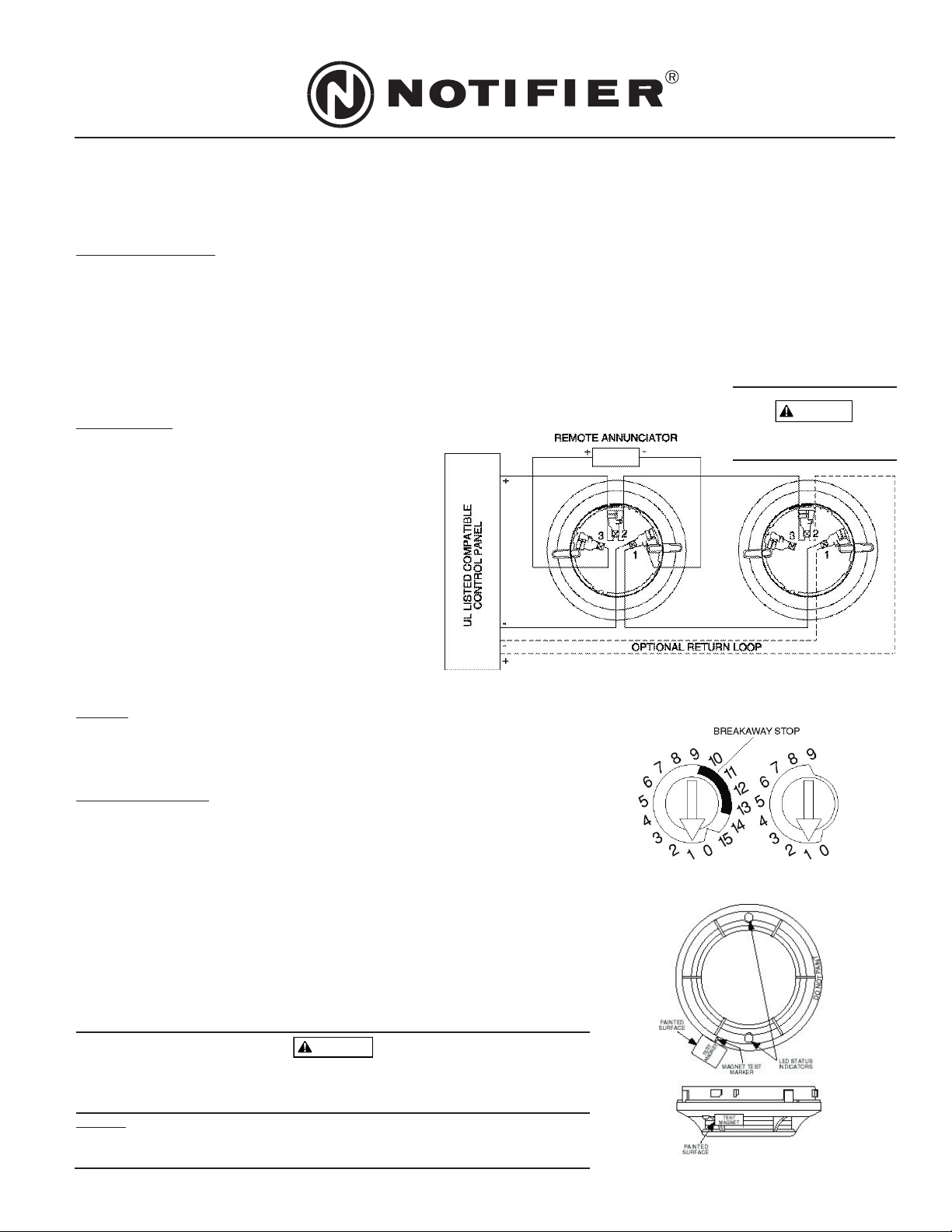
1. Hold the test magnet in the magnet test area as shown.
2. The sensor should alarm the panel.
Two LEDs on the sensor are controlled by the panel to indicate sensor status. Coded signals, transmitted from the panel, can cause the LEDs to blink, latch
on, or latch off. Refer to the control panel technical documentation for sensor LED status operation and expected delay to alarm.
B. Smoke Entry: Aerosol Generator (Gemini 501)
The Gemini model 501 aerosol generator can be used for smoke entry testing. Set the generator to represent 4%/ft. to 5%/ft. obscuration as described in
the Gemini 501 manual. Using the bowl shaped applicator, apply aerosol until the panel alarms.
A sensor that fails any of these tests should be cleaned as described under CLEANING, and retested. If the sensor fails after cleaning, it must be replaced and
returned for repair.
When testing is complete, restore the system to normal operation and notify the proper authorities that the system is back in operation.
CLEANING
It is recommended that the detector be removed from its mounting base to facilitate cleaning. The detector is cleaned as follows:
NOTE: Before removing the detector, notify the proper authorities that the smoke detector system is undergoing maintenance and will be temporarily out of
service. Disable the zone or system undergoing maintenance to prevent unwanted alarms.
1. Remove the detector cover by prying away the four side tabs with a small-bladed screwdriver, and then pulling the cover from the base.
2. Vacuum the screen carefully without removing it. If further cleaning is required continue with Step 3,
otherwise skip to Step 7.
3. Remove the screen assembly/chamber cover by pulling it straight out (see Figure 4).
4. Clean the chamber by vacuuming or blowing out dust and particles.
5. Replace the sensing chamber cover, aligning the arrow on the top with arrow on the printed circuit
board.
6. To replace the screen, place it over the chamber assembly, turning it until it snaps into place.
7. Replace the cover using the LEDs to align the cover and then gently pushing it until it locks into place.
8. Reinstall the detector.
9. Test the detector as described in TESTING.
10. Reconnect disabled circuits.
11. Notify the proper authorities that the system is back on line.
Laser Safety Information
This smoke detector does not produce any hazardous laser radiation and is certified as a Class 1 laser
product under the U.S. Department of Health and Human Services (DHHS) Radiation Performance Standard
according to the Radiation Control for Health and Safety Act of 1968.
Any radiation emitted inside the smoke detector is completely within the protective housings and external
covers. The laser beam cannot escape from the detector during any phase of operation.
The Center of Devices and Radiological Health (CDRH) of the U.S. Food and Drug Administration implement-
ed regulations for laser products on August 2, 1976. These regulations apply to laser products manufactured
after August 1, 1976. Compliance is mandatory for products marketed in the United States.
Use of controls, adjustments, or performance of procedures other than those specified in this manual may result in hazardous radiation exposure.
REMOVABLE
COVER
SENSING
CHAMBER
SCREEN
ASSEMBLY
N200-06-00 2 I56-057-02R
© 2001 Notifier
A78-2586-00
Figure 4.
FCC Statement
This device complies with part 15 of the FCC Rules. Operation is subject to the following two conditions: (1) This device may not cause harmful inter-
ference, and (2) this device must accept any interference received, including interference that may cause undesired operation.
Note: This equipment has been tested and found to comply with the limits for a Class A digital device, pursuant to Part 15 of the FCC Rules. These
limits are designed to provide reasonable protection against harmful interference when the equipment is operated in a commercial environment. This
equipment generates, uses and can radiate radio frequency energy and, if not installed and used in accordance with the instruction manual, may
cause harmful interference to radio communications. Operation of this equipment in a residential area is likely to cause harmful interference in which
case the user will be required to correct the interference at his own expense.
Please refer to insert for the Limitations of Fire Alarm Systems
www.PDF-Zoo.com