Installing RS485 Interface Module PCBInstalling RS485 Interface Module PCB
997-299, Issue 3 October 2002
1
Installing RS485 Interface Module PCBInstalling RS485 Interface Module PCB
997-299, Issue 3 October 2002
1
Check your equipment....Check your equipment....
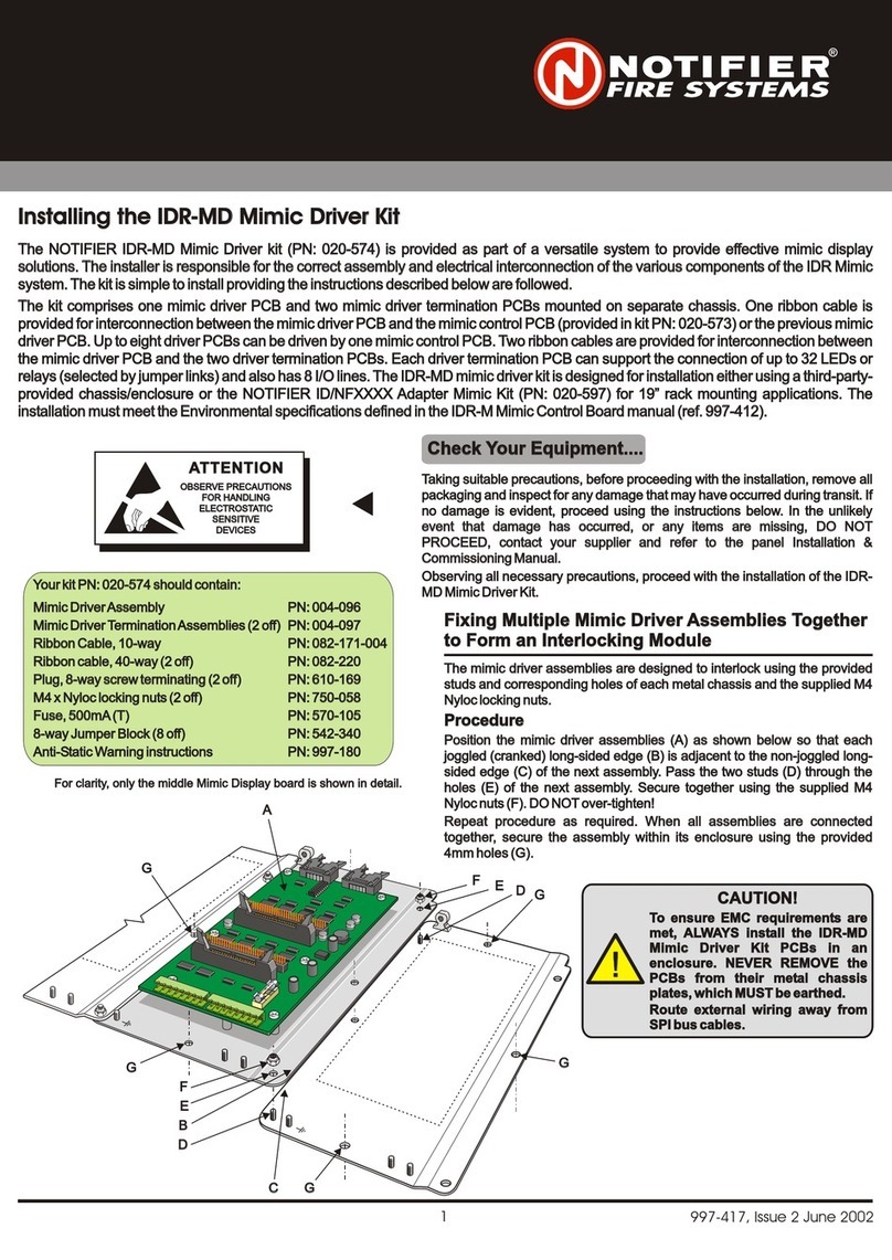
The RS485 Interface Module PCB kit (020-553) is fitted in the panel to provide an interface for the RS485 Communications Link. The
RS485 Interface Module PCB mounts on the right-hand side of the PCB assembly at connector PL3.
Note: When stated, refer to the appropriate product Installation, Commissioning & Configuration Manual.
The anel to provide an interface for the RS485 Communications Link. The
RS485 Interface Module PCB mounts on the right-hand side of the
RS485 Interface Module PCB kit (020-553) is fitted in the p
PCB assembly at connector PL3.
Note: When stated, refer to the appropriate product Installation, Commissioning & Configuration Manual.
Take suitable anti-static precautions, such as wearing a grounded wrist
strap, when following ALL instructions. Remove all packaging from the
equipment and ensure that it has not been damaged in transit and all
items have been received - see checklist at left, before proceeding any
further. If no damage is evident, proceed using the instructions below. In
the unlikely event that damage has occurred or items are missing, DO
NOT PROCEED, contact your supplier and refer to Installation,
Commissioning & Configuration Manual.
Your kit PN: 020-553 should contain:
RS485 Interface Module PCB PN: 124-316
Supporting Pillars (x2) PN: 423-312
150R Termination Resistors (x2) PN: 170-073-151
Anti-Static Warning instructions PN: 997-180
Your kit PN: 020-553 should contain:
RS485 Interface Module PCB PN: 124-316
Supporting Pillars (x2) PN: 423-312
150R Termination Resistors (x2) PN: 170-073-151
Anti-Static Warning instructions PN: 997-180
!!WARNING - Make sure
ALL power to the panel has been disconnected.
you have a PC back-up of the current configuration data and
OBSERVE PRECAUTIONS
FOR HANDLING
ELECTROSTATIC
SENSITIVE
DEVICES
OBSERVE PRECAUTIONS
FOR HANDLING
ELECTROSTATIC
SENSITIVE
DEVICES
ATTENTIONATTENTION
AA
DD
EE
BB
FF
CC
2
3
3
394-191 Issue XX
Fitting the RS485 Interface Module PCB
With the back box installed in its chosen location, follow this procedure:
1Remove the cover, refer to Installation, Commissioning &
Configuration Manual, to expose the panel electronics.
Disconnect the battery interlink wire from the batteries and
isolate the mains supply.
2Carefully fit the two plastic PCB support pillars (A) in to the holes
(B) on the right-hand side of the PCB Assembly (C).
3Fit the RS485 Interface Module PCB (D).
i. Make sure the RS485 Interface Module PCB components are
facing the membrane and rest it in the PCB Support pillar guides.
ii. Gently ease the RS485 PCB and PCB Support pillars away
from the membrane and carefully slide the RS485 PCB down
the pillars until the 10-way socket (E) aligns with the
connector, PL3 (F) on the PCB Assembly ensuring that the
components do NOT foul on the membrane.
iii. Carefully return the PCB Support pillars to their normal position
and with a firm and constant pushing action, connect the PCB.
i. Make sure the RS485 Interface Module PCB components
are facing away from the membrane and rest it in guides of
the PCB Support pillars.
ii. Carefully slide the PCB along the pillars until the 10-way socket
(E) aligns with the connector, PL3 (F) on the PCB Assembly.
iii. With a firm and constant pushing action, connect the RS485
PCB to the PCB Assembly.
Fitting to PCB Assembly PN: 394-191-001, 002 or 003
Fitting to PCB Assembly PN: 394-191 Issue 4 or later
Fitting the RS485 Interface Module PCB
With the back box installed in its chosen location, follow this procedure:
1Remove the cover, refer to Installation, Commissioning &
Configuration Manual, to expose the panel electronics.
Disconnect the battery interlink wire from the batteries and
isolate the mains supply.
2Carefully fit the two plastic PCB support pillars (A) in to the holes
(B) on the right-hand side of the PCB Assembly (C).
3Fit the RS485 Interface Module PCB (D).
i. Make sure the RS485 Interface Module PCB components are
facing the membrane and rest it in the PCB Support pillar guides.
ii. Gently ease the RS485 PCB and PCB Support pillars away
from the membrane and carefully slide the RS485 PCB down
the pillars until the 10-way socket (E) aligns with the
connector, PL3 (F) on the PCB Assembly ensuring that the
components do NOT foul on the membrane.
iii. Carefully return the PCB Support pillars to their normal position
and with a firm and constant pushing action, connect the PCB.
i. Make sure the RS485 Interface Module PCB components
are facing away from the membrane and rest it in guides of
the PCB Support pillars.
ii. Carefully slide the PCB along the pillars until the 10-way socket
(E) aligns with the connector, PL3 (F) on the PCB Assembly.
iii. With a firm and constant pushing action, connect the RS485
PCB to the PCB Assembly.
Continued overleaf....Continued overleaf....

