Novalynx 210-421x-A User manual

DOC 210-421x-A UM 20210322
210-421x-A
User Manual
Dual Set Point Temperature Alarm
210-421-A (Air Temperature)
210-421W-A (Water, Soil Temperature)
Air Temperature Sensor
Water and Soil Temperature Sensor
Phone (530) 823-7185

NovaLynx Corporation________________________________________________________________________________
210-421x-A Page 2 March 2021
Receiving and Unpacking
Carefully unpack all components and compare to the packing list. Notify NovaLynx Corporation
immediately concerning any discrepancy. Inspect equipment to detect any damage that may have
occurred during shipment. In the event of damage, any claim for loss must be filed immediately with
the carrier by the consignee. Damages to equipment sent via Parcel Post or UPS require the consignee
to contact NovaLynx Corporation for instructions.
Returns
If equipment is to be returned to the factory for any reason, call NovaLynx between 8:00 a.m. and 4:00
p.m. Pacific Time to request a Return Authorization Number (RA#). Include with the returned
equipment a description of the problem and the name, address, and daytime phone number of the
sender. Carefully pack the equipment to prevent damage or additional damage during the return
shipment. Call NovaLynx for packing instructions in the case of delicate or sensitive items. If packing
facilities are not available take the equipment to the nearest Post Office, UPS, or other freight service
and obtain assistance with the packaging. Please write the RA# on the outside of the box.
Warranty
NovaLynx Corporation warrants that its products are free from defects in material and workmanship
under normal use and service for a period of one year from the date of shipment from the factory.
NovaLynx Corporation's obligations under this warranty are limited to, at NovaLynx's option: (i)
replacing; or (ii) repairing; any product determined to be defective. In no case shall NovaLynx
Corporation's liability exceed product's original purchase price. This warranty does not apply to any
equipment that has been repaired or altered, except by NovaLynx Corporation, or that has been
subjected to misuse, negligence, or accident. It is expressly agreed that this warranty will be in lieu of
all warranties of fitness and in lieu of the warranty of merchantability.
Address
NovaLynx Corporation
431 Crown Point Circle, Suite 120
Grass Valley, CA 95945-9531 USA
Phone: (530) 823-7185
Email: nova@novalynx.com
Website: www.novalynx.com
Copyright © 1988-2021 by NovaLynx Corporation

NovaLynx Corporation________________________________________________________________________________
210-421x-A Page 3 March 2021
CONTENTS
1 FORWARD ....................................................................................................................................................................... 4
2 INTRODUCTION ............................................................................................................................................................... 4
3 SPECIFICATIONS .............................................................................................................................................................. 5
4 PRE-INSTALLATION CHECKOUT ....................................................................................................................................... 5
4.1 Power Supply Connection ....................................................................................................................................... 6
4.2 Menu Navigation ..................................................................................................................................................... 6
4.2.1 MENU Button .................................................................................................................................................. 6
4.2.2 UP Button ........................................................................................................................................................ 6
4.2.3 DOWN Button ................................................................................................................................................. 7
4.2.4 CLEAR Button .................................................................................................................................................. 7
4.2.5 GO Button ....................................................................................................................................................... 7
4.3 Program Alarm Thresholds ..................................................................................................................................... 7
4.4 Program Alarm Delays ............................................................................................................................................ 8
4.5 DIP Switch Settings .................................................................................................................................................. 8
5 TEMPERATURE SENSOR INSTALLATION .......................................................................................................................... 9
5.1 Air Temperature Sensor and Sunshield .................................................................................................................. 9
5.2 Water / Soil Temperature Sensor ........................................................................................................................... 9
6 TEMPERATURE ALARM INSTALLATION ......................................................................................................................... 10
6.1 Controller Location ............................................................................................................................................... 10
6.2 Controller Mounting ............................................................................................................................................. 10
7 CONNECTIONS ............................................................................................................................................................... 11
7.1 Temperature Sensor Connection .......................................................................................................................... 11
7.2 Power Connection ................................................................................................................................................. 11
7.3 Relay Connections ................................................................................................................................................. 12
8 ALARM FUNCTIONS ....................................................................................................................................................... 12
APPENDIX A ........................................................................................................................................................................... 13

NovaLynx Corporation________________________________________________________________________________
210-421x-A Page 4 March 2021
1 FORWARD
Thank you for purchasing NovaLynx products. NovaLynx has been designing and manufacturing
weather instruments since 1988. NovaLynx represents several well-known brands of quality
manufacturers, including Gill Instruments, RM Young, Kipp & Zonen, and Vaisala. It is our hope that
our products will meet all your monitoring requirements.
2 INTRODUCTION
The 210-421x-A Dual Set Point Temperature Alarm includes an air temperature sensor or a water/soil
temperature sensor. Two independently controlled relays are provided to operate external equipment
such as alarm lights or sirens. The temperature alarm can function as a frost protection controller.
The back-lit LCD display is easily visible through the transparent cover. With the cover removed the
unit is programmed by push-button controls without the need to connect a computer. All set points
and the minimum and maximum temperatures are stored in non-volatile memory. DIP switch settings
select the units (°F or °C) and enable/disable the internal buzzer.
Programmable Features:
Alarm Set Point Temperature threshold for alarm
Channel 1 Select > (greater than) or < (less than) operator and a value (Default < 32° F or < 0° C)
Channel 2 Select > (greater than) or < (less than) operator and a value (Default < 28° F or < -2° C)
Alarm ON Delay 0-99 seconds before alarm/ relay activation (Default 5 sec)
Alarm OFF Delay 0-99 seconds before alarm / relay de-activation (Default 5 sec)
When in alarm mode, a blinking LED indicates which relay(s) are active. Each relay can be connected in
normally open or the normally closed mode.
It is the responsibility of the installer to properly insulate any connections to the relay terminals,
especially if high voltages are present. It is also important to provide an earth grounding wire to
protect the controller from static discharge, whether or not the relays are connected.

NovaLynx Corporation________________________________________________________________________________
210-421x-A Page 5 March 2021
3 SPECIFICATIONS
The controller requires a 12V AC or DC power supply. The NovaLynx 200-WS21P Power Pack (sold
separately) is suitable in most applications, and comes with the proper terminals for easy connection.
4 PRE-INSTALLATION CHECKOUT
The controller can be operated before installation to become familiar with the menus and
programmable features. You will need a power supply and the controller. The temperature sensor is
usually connected prior to shipping. Refer to Appendix A for connection points.
Display LCD, 2x16 characters, 3x8 mm character size, backlit
Indicators Green LED - Power, Red LEDs - Alarms
Setup DIP switch: WIND/TEMP, MPH/KPH, DEG F/DEG C, BUZZER/DISABLE
Programming Pushbutton: MENU, UP, DOWN, CLEAR, GO
Connections All user connections 1/4" male spade terminals (connectors supplied)
Relay specifications Form "C" (SPDT) N.O. and N.C. Contact rating: 3A @ 24Vdc / 115 VAC
Alarm ON / OFF delay range 0 to 99 seconds
Timing accuracy ± 2%
Measurement range -40° to 160° F (-40° to 60° C)
Integration interval 2 seconds
Input Power 12V AC or DC, 150 mA (50 mA when backlight disabled)
Operating temperature -20°C to +50°C
Mounting Knock-outs in back surface for screw mounting to a panel
Dimensions 5.12 x 6.25 x 2.95 inch (13.0 x 15.9 x 7.5 cm)
Weight / Shipping 2 lbs (0.91 kg) / 3 lbs (1.4 kg)
Type Thermistor, 10K ohm @ 25°C ± 3%
Range -40° to 160° F (-40° to 60° C)
Accuracy ± 1° F (± 0.56° C)
Probe case Aluminum
Probe dimensions 2" L x 0.25" dia (51 mm L x 6.4 mm dia)
Cable 40 feet (12 m), 2-conductor, 24 AWG, shielded
Type Precision thermistor, 10k @ 25° C
Range -40 to 140° F (-40 to +60° C)
Accuracy ±0.3° C
Time constant 60 seconds
Probe case Stainless steel
Probe dimensions 3" L x 0.375" dia (76 mm L x 10 mm dia)
Cable 40 feet (12 m) 2-conductor, 18 AWG, shielded, direct burial
110-WS-16TWS Water and Soil Temperature Sensor Specification
110-WS-16T Air Temperature Sensor Specification
210-421x-A Dual Setpoint Controller Specification

NovaLynx Corporation________________________________________________________________________________
210-421x-A Page 6 March 2021
4.1 Power Supply Connection
The 200-WS-21P Power Pack (sold separately) is provided with ¼"
spade connectors that fit the terminals at the lower left corner of
the temperature alarm circuit board. If you are using a different
power supply, crimp the provided accessory connectors to your
12V AC or DC power source. Plug the AC Adapter into a wall outlet
and check that the green power LED on the temperature alarm
circuit board turns on.
The display should look similar to the
illustration on the right. This is the
operating mode screen.
NOTE: If you see the word "Wind:"
instead of "Temp:" then the DIP
switches are in the wrong position.
Refer to the "DIP Switch Settings"
section of the manual to correct this
situation.
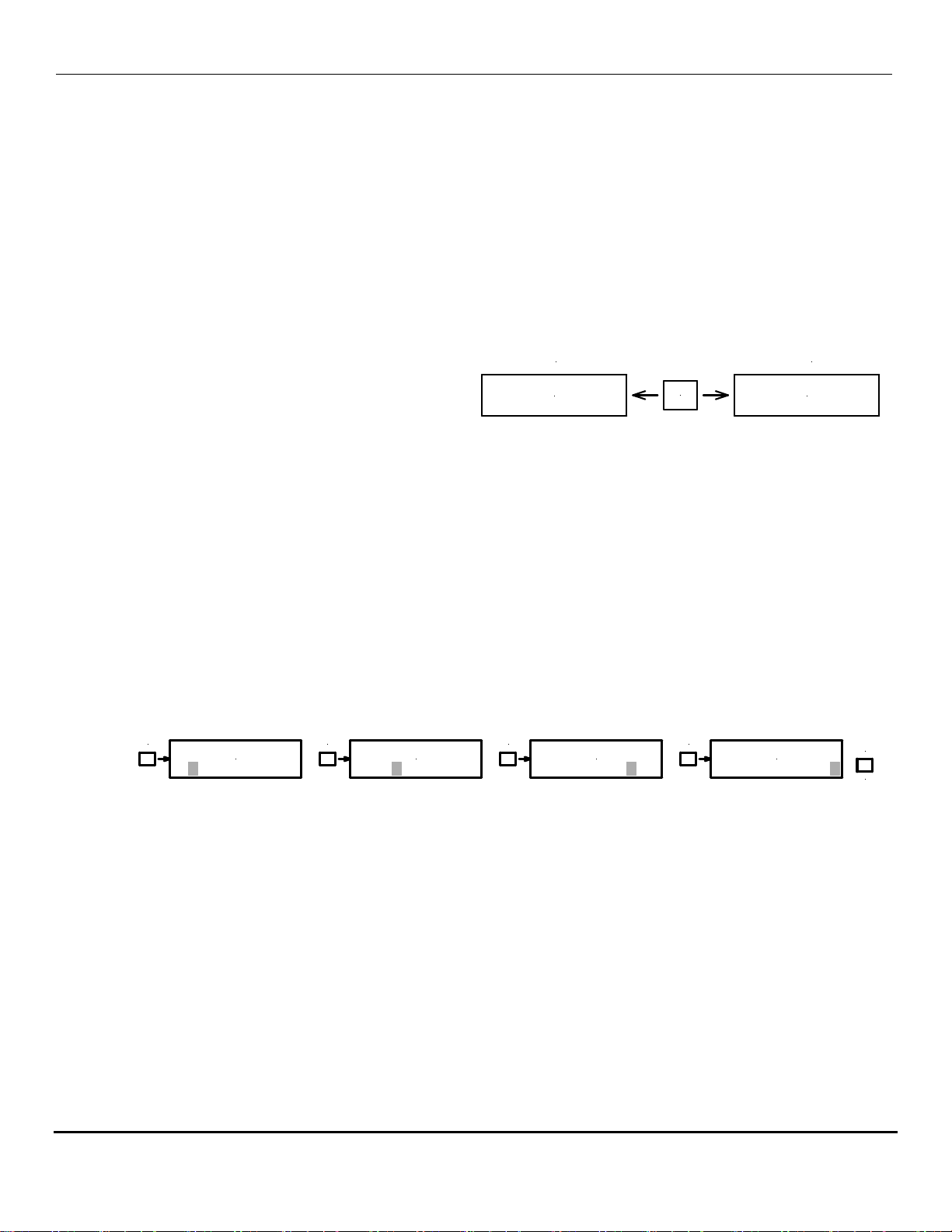
4.2 Menu Navigation
The programming buttons are below the display.
4.2.1 MENU Button
Press the MENU button. One of three sub-menus will be displayed (depending on which was
viewed last). Additional uses of the MENU button will be discussed in the following
programming section.
4.2.2 UP Button
Use the UP button to cycle through the menus.
1. Alarm Delays – the delay (seconds) before and after an
alarm threshold is crossed.
2. Temp Alarms – the set points at which the alarm occurs.
3. Temps – displays the lowest and highest temperatures
recorded since the CLEAR button was pressed.
NOTE: Do NOT use the DOWN button to cycle through the menus. A firmware error causes the
unit to stop at the "Temp Alarms" menu. If this happens, reboot the processor by disconnecting
power to the unit for a few seconds.
MENU UP DOWN CLEAR GO
ACin / DCin
ACin/DCgnd
200-WS-21P
AC Adapter
(sold separately)
(DC+)
(DC-)
A/DM
Menu Up Dn Clr Go
PROGRAMMING
BUTTONS
POWER LED
Temp: 71.0 (°F)
1:< 32 2:< 28
Temps (°F)
Lo:-10.0 Hi:78.0
Temp Alarms(°F)
1:< 32 2:< 28
Alarm Delays (s)
ON: 5 OFF: 5
UP
UP
UP
NovaLynx Corporation________________________________________________________________________________
210-421x-A Page 7 March 2021
4.2.3 DOWN Button
Use the DOWN button to select values when in an editable field. (Do NOT use the DOWN button
to cycle through the menus.)
4.2.4 CLEAR Button
The CLEAR button performs the following actions:
1. If the user is in an editable field, the field will be set to zero.
2. If the user is viewing the Temps Lo and Hi menu, the recorded values will be set to zero.
3. If the unit is alarming, all delay counters will be cleared.
4.2.5 GO Button
Press GO from any menu to return to
operating mode.
If the unit is already in operating mode,
press GO to pause the system and
disable all alarms.
IMPORTANT: Whenever the controller is turned on it is in Operating Mode and the alarms are
active. If the system was in Paused Mode before a power failure, it will restart in Operating Mode
when power is restored.
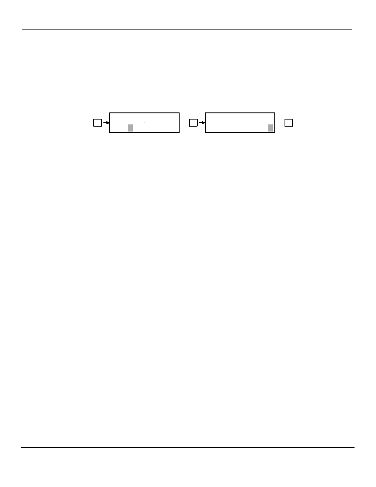
4.3 Program Alarm Thresholds
To begin, navigate to the Temp Alarms menu:
1. Press GO until the display shows the operating mode screen (see GO Button, above).
2. Press MENU to bring up one of the three sub-menu displays.
3. Press UP to reach the Temp Alarms sub-menu. (Do NOT use the DOWN button to cycle through
the menus.)
Temp Alarms(°F)
1:< 32 2:< 28
Temp Alarms(°F)
1:< 32 2:< 28
Temp Alarms(°F)
1:< 32 2:< 28
Temp Alarms(°F)
1:< 32 2:< 28
MENU
MENU
MENU
MENU
MENU
(END)
Channel #1 Operator Channel #1 Value Channel #2 Operator Channel #2 Value
4. Press MENU again. A blinking block cursor will appear on the Channel #1 Operator.
a. < Operator means the alarm will occur when the temperature is less than the Value.
b. > Operator means the alarm will occur when the temperature is greater than the Value.
c. Press UP or DOWN to change the Operator.
d. Press MENU to advance to Channel #1 Value.
e. Press UP or DOWN to change the Value.
5. Press MENU again to advance to Channel #2 Operator.
a. Set the Channel #2 Operator. Press MENU to advance to the Channel #2 Value.
b. Set the Channel #2 Value. Press MENU to complete programming the Temp Alarms.
c. Press GO to return to the operating mode screen.
Temp: 71.4 (°F)
1:< 32 2:< 28
GO
System Paused
GO to resume
Operating Mode
Paused Mode
NovaLynx Corporation________________________________________________________________________________
210-421x-A Page 8 March 2021
4.4 Program Alarm Delays
To begin, navigate to the Alarm Delays menu:
1. Press GO until the display shows the operating mode screen (see GO Button, above).
2. Press MENU to bring up one of the three sub-menu displays.
3. Press UP to reach the Alarm Delays sub-menu. (Do NOT use the DOWN button to change
menus.)
Alarm Delays (s)
ON: 5 OFF: 5
Alarm Delays (s)
ON: 5 OFF: 5
MENU
MENU
MENU
(END)
ON Delay OFF Delay
4. Press MENU again. A blinking block cursor will appear at the ON Delay.
Note: The range is 0 to 99 seconds.
a. Press UP or DOWN to change the ON Delay.
b. Press MENU to advance to the OFF Delay.
c. Press UP or DOWN to change the OFF Delay.
d. Press MENU to complete programming the Alarm Delays.
e. Press GO to return to the operating mode screen.
4.5 DIP Switch Settings
The DIP switches are pre-set at the factory and should not need to be adjusted. However,
sometimes during installation they get changed accidentally.
1. The Dual Set Point controller is designed to operate as either a wind alarm or temperature
alarm. The DIP switch marked "Wt" determines which mode is selected. Set this switch to
ON for temperature alarms.
2. The "Wu" switch sets the wind speed units. This is not relevant to the temperature alarms,
so it doesn't matter how this switch is set.
3. The "Tu" switch sets the temperature units. Set the "Tu" switch to OFF to display
temperature in degrees Fahrenheit (°F). Set the switch ON for degrees Celsius (°C).
4. The "Si" (silent) switch determines whether the internal buzzer operates. The normal
setting is OFF which allows the buzzer to operate. The ON setting silences the buzzer.
The controller checks the positions of the DIP switches when the unit initializes during power-up.
Disconnect the AC Adapter for a few seconds and then re-connect power to change modes after
changing any switches.

NovaLynx Corporation________________________________________________________________________________
210-421x-A Page 9 March 2021
5 TEMPERATURE SENSOR INSTALLATION
5.1 Air Temperature Sensor and Sunshield
The 110-WS-16T Temperature Sensor is suitable for monitoring ambient air temperatures. It is not
designed to be buried in soil or submerged in water. When installed indoors, place it at an appropriate
height (remember that hot air rises) in an area that has adequate air movement.
When used outdoors, the sensor must be installed in a solar radiation shield to protect it from direct
sunlight and rain. The NovaLynx 380-280 Solar Radiation Shield is an economical option for use with
the 110-WS-16T.
The 380-280 Solar Radiation Shield (sold separately) is fitted with two universal bushings that help
center and hold the sensor in place. The bushings are suitable for use with smooth probes, such as
temperature sensors.
Sensor Installation
1) Insert the probe until the tip is within an inch (25 mm) of the upper cap.
2) Route the cable through the cable clamp that is on the underside of the
bracket. The clamp will provide strain relief for the cable and ensure the
sensor will not fall out.
For Pipe Mounting
1) Remove the U-bolt from the mounting bracket.
2) Secure the radiation shield to a 1 ½" mast (38 mm). 380-280 Solar Radiation Shield
For Surface Mounting
1) Remove the U-bolt from the bracket.
2) Mark the outer two holes of the mounting bracket on the surface.
3) Drill the two holes marked in the previous step into the surface.
4) Attach the radiation shield with appropriate fasteners (not included).
Route the sensor cable to the temperature alarm in the most direct manner. Leave a "drip loop" of
cable below the entry point to the equipment enclosure to help keep moisture out. Fasten the cable to
the mast with cable ties to prevent whipping during high winds. For best results, use cable ties that are
resistant to ultra-violet radiation and place them at two foot intervals. Do not over-tighten.
5.2 Water / Soil Temperature Sensor
The 110-WS-16TWS Water and Soil Temperature Sensor has a stainless steel probe tip and direct burial
cable jacket, making it more robust. The cable can be buried directly in soil or placed in conduit to
protect it from burrowing animals. The probe should be shaded from sunlight for best results.
NovaLynx Corporation________________________________________________________________________________
210-421x-A Page 10 March 2021
6 TEMPERATURE ALARM INSTALLATION
6.1 Controller Location
To be effective the temperature alarm must be in a location where one can view the display and hear
the alarm. At the same time it should not be accessible to unauthorized personnel. It will need to be
mounted near a 120V AC receptacle for power. If the controller is inside a building the sensor cable
may need to be routed outside so that the sensor can be exposed ambient air conditions.
6.2 Controller Mounting
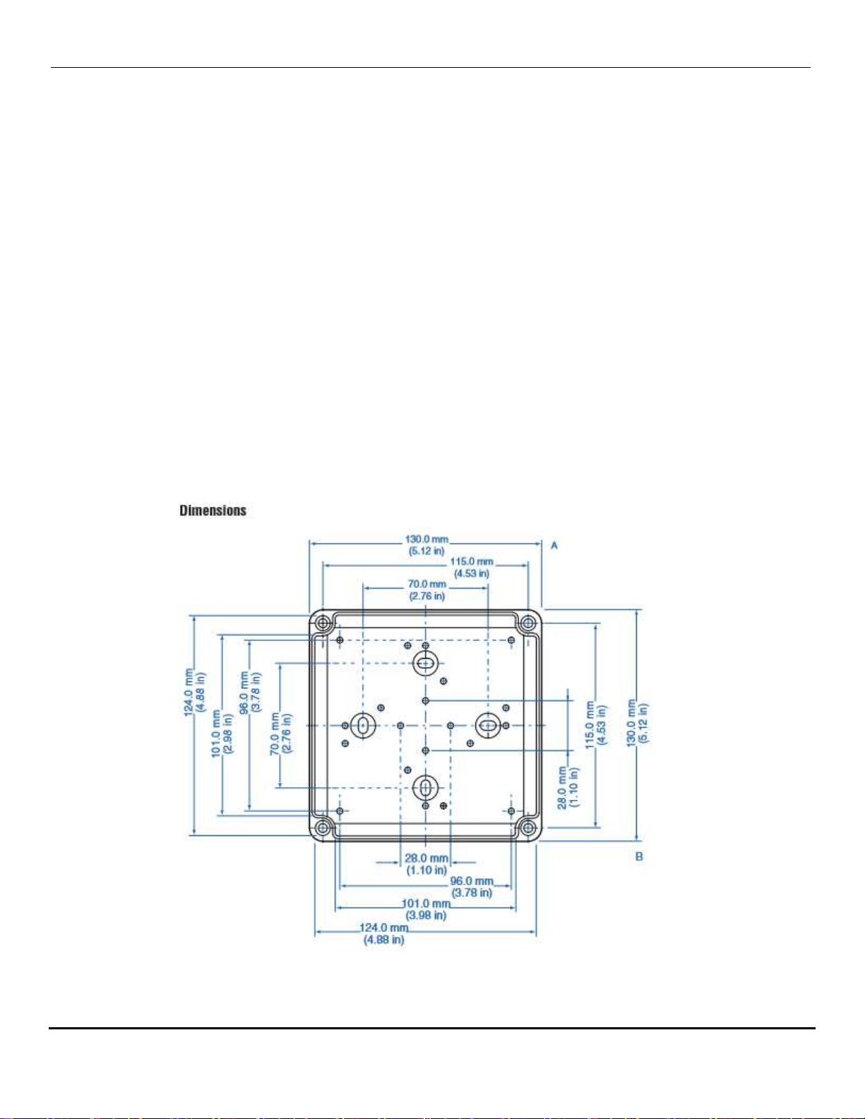
There are 4 knock-out locations inside the controller box for placing screws. It will be necessary to
remove the circuit board to access these points. After mounting the case to your wall or panel, install
the small caps that are included in the accessory bag to cover the screw locations. The caps will help
keep moisture from entering the box. Replace the controller circuit board and secure it with the
mounting screws.

NovaLynx Corporation________________________________________________________________________________
210-421x-A Page 11 March 2021
7 CONNECTIONS
Please refer to the connection diagram in Appendix A of this manual.
The temperature sensor and AC adapter (NovaLynx 200-WS-21P, sold separately) are supplied with
connectors that fit the ¼" spade terminals on the temperature alarm circuit board. Extra connectors
are provided for connecting an earth ground and alarm relay connections. You will need a crimp tool or
heavy duty pliers to make these connections. You will also need to provide insulated wire for the earth
ground and relay connections. Stranded wire (14 to 16 AWG) is preferred.
Standard Wire Wire Connector with an
Connector extra lug for Earth Ground
7.1 Temperature Sensor Connection
Route the temperature sensor cable through the gland fitting and into the case. Connect the earth
ground connector with the tab facing down, to make room for the other connections. Attach the red
and black wires as indicated on the drawing.
Prepare a suitable length wire with a standard wire connector, and connect it to the lug on the earth
ground connector. Route the other end of this wire to a good earth ground – an electrical box with an
earth connection or a metal cold water pipe that actually enters the ground. Failure to provide a
ground may cause erratic operation and make the system more vulnerable to damage from nearby
lightning strikes.
7.2 Power Connection
NOTE: It is good practice to program the set points and delays, and then operate the system using the
visible LEDs and buzzer as alarm indicators for testing the system before connecting the relays to your
external equipment.
Route the wiring from the AC Adapter or other power supply through the cable gland and attach the
positive terminal (marked with red shrink wrap or a white stripe on one lead) to the ACin / DCin
terminal. Connect the ground wire to the ACin / DCgnd terminal. The power input accepts 12 volts AC
or DC.
NovaLynx recommends connecting the AC Adapter to an outlet with a surge suppressor. Power strips
with surge suppressors are often used to protect computer equipment and are readily available.
Check your connections to make sure there are no stray wires that could cause a short circuit. Plug in
your power supply. The green power LED should turn on and the word "Temp:" will be displayed. If you
see the word "Wind:" instead of "Temp:" then the DIP switches are in the wrong position. Refer to the
"DIP Switch Settings" section of the manual to correct this situation.

NovaLynx Corporation________________________________________________________________________________
210-421x-A Page 12 March 2021
7.3 Relay Connections
There are two internal relays for alarms or operating pumps, etc. Please refer to the specifications to
ensure the internal relays are rated for the load you intend to control. If the contact rating is less than
required an external relay will be needed (not supplied). Refer the installation to a qualified electrical
contractor.
WARNING: Turn off all power sources before connecting to the relays. Identify which relay(s) you will
be using and which function is required. When there is no alarm, the N.O. contacts are OPEN. This
contact is used to turn something ON when there is an alarm. The N.C. contact does the opposite, i.e.
turns something OFF when there is an alarm.
The relay contacts are "dry". Connect the Hot lead to C1 for relay #1 or to C2 for relay #2. Connect the
corresponding N.O. or N.C. output to the load. The return side of the load must be connected to
Neutral to complete the circuit. Connect the grounding wire to the Earth Ground lug.
WARNING: The unused spade lug (N.O. or N.C.) will be electrically HOT under some circumstances.
Place a spare connector or insulating tape over the unused lug to prevent anyone from touching it
accidentally.
Be sure you have programmed the temperature alarm to the settings you desire and the temperature
alarm system is operating properly before you connect power to your external devices.
8 ALARM FUNCTIONS
The temperature alarm must be in Operating Mode in order for the alarms to
activate. Alarms are disabled while programming and when the unit is in
Paused Mode. Be sure to return the unit to Operating Mode when the alarm
function is required. (See GO button instructions). Operating Mode Screen
Alarm Channel #1:
The audible alarm will beep at 400 millisecond intervals (if enabled) and the relay will energize when
the threshold and Delay-Before-ON timeout has occurred. A red LED on the circuit board will also flash.
Alarm Channel #2:
The audible alarm will beep at 200 millisecond intervals (if enabled) and the relay will energize when
the threshold and Delay-Before-ON timeout has occurred. A red LED on the circuit board will also flash.
When both alarms occur together, the beeping will be at 200 millisecond intervals.
Paused Mode
Press the GO button to place the controller in Paused Mode to turn off the alarms and relays. The
controller will remain in this mode indefinitely unless the power to the controller is interrupted. Press
GO again to return to operating mode.
CLEAR Button (temporarily clears the alarm)
The CLEAR button will stop the alarms by clearing the Delay Before ON timeout. If the temperature
is beyond the programmed threshold the alarm will activate again when the timeout occurs.
Temp: 71.4 (°F)
1:< 32 2:< 28

DOC 210-421x-A UM 20210322
APPENDIX A
Wind and Temp Alarm
JDC
3-18-2021
890-0089-02
Connection Diagram
210-421x-A
N/A
ACin / DCin
WND+
ALARM RELAYS
#1 #2
NC1 NO1 C1 NC2 NO2 C2
Wt WuTuSi
Buzzer
DIP Switches
ACin/DCgnd
WNDg
EARTH
TMP2
TMP1
CONTRAST
ADJUSTMENT
A/DM
BACKLIGHT
ENABLE JUMPER
(remove to turn off backlight)
Menu Up Dn Clr Go
PROGRAMMING
BUTTONS
MODE
WIND UNITS
TEMP UNITS
BUZZER
WIND
MPH
DEG F
BUZZ
TEMP
KPH
DEG C
SILENT
ON OFF
Wt
Wu
Tu
Si
DIP SETTINGS
DUAL SET POINT TEMPERATURE ALARM
210-421-A and 210-421W-A
(Alarms OFF)
(Red)
(Black)
(Shield)
CAUTION: TURN OFF ALL
POWER SOURCES BEFORE
CONNECTING TO THE RELAYS
User Relay Connections
200-WS-21P
AC Adapter
(sold separately)
User-supplied earth ground
connection. Attaches to lug
on sensor shield terminal.
POWER LED
ALARM LEDS
(DC+)
(DC-)
110-WS-16T
or
110-WS-16TWS
Temperature Sensor
02 add 110-WS-16TWS sensor
This manual suits for next models
1
Table of contents
Other Novalynx Measuring Instrument manuals


Popular Measuring Instrument manuals by other brands

Precision Digital Corporation
Precision Digital Corporation PROVU PD6262 Series instruction manual

Ronde & Schwarz
Ronde & Schwarz FPL Series user manual

WIKA
WIKA CEP3000 operating instructions

Lutron Electronics
Lutron Electronics MO-2014 Operation manual

Neoss
Neoss NeoScan 2000 manual

GW Instek
GW Instek GSP-9300B user manual


