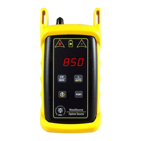
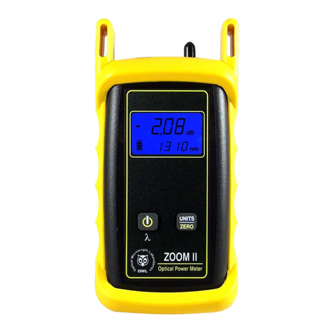
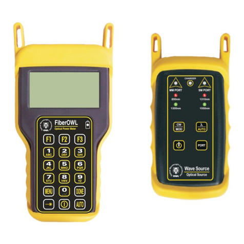
OWL F7BMS MM User manual

•
O
p
t
i
c
a
l
W
a
v
e
l
e
n
g
t
h
L
a
b
o
r
a
t
o
r
i
e
s
•
T
h
e
W
I
S
E
C
h
o
i
c
e
i
n
O
p
t
i
c
a
l
F
i
b
e
r
T
e
s
t
e
r
s
OWL
Optical Wavelength Laboratories
Revision 1.0b
Optical Wavelength Laboratories (OWL)
N9623 Old Hwy 12
Whitewater, WI 53190
Phone: 262-473-0643
Internet: http://OWL-inc.com
OPERATIONS GUIDE
FIBER OWL 7 SERIES BI-DIRECTIONAL CERTIFIERS
MODEL #s:
F7BMS (MM / SM)
F7BMX (MM only)
F7BMV (MM / VFL)
F7BSX (SM only)
F7BSV (SM / VFL)

TABLE OF CONTENTS
INTRODUCTION
BEFORE YOU BEGIN 4
ABOUT THIS MANUAL 4
DESCRIPTION 5
APPLICATIONS
PAIR MODE 6
BIDI MODE 7
CERT MODE 8
LOSS MODE 9
OPTICAL POWER MEASUREMENT 10
OPTICAL LENGTH MEASUREMENT 11
TEST PATCH CORDS 12
GENERAL FEATURES
PRECAUTIONS 13
LABEL 13
GENERAL FEATURES 14
SPECIFICATIONS 15
WARRANTY INFORMATION 16
SUPPORTED CABLING STANDARDS 16
CONTACT INFORMATION 16
ROLES 17
TEST PROCEDURES
BEFORE YOU BEGIN 18
STEP 1: GATHER LINK SETUP INFORMATION 19
LINK PLANNING WORKSHEET 20
KEY TEST PARAMETERS 21
FIBER STANDARD 21
TEST MODE 21
FIBER TYPE 21
FIBER TYPE - LINK TYPES 22
TEST CORD TYPE 23
SPLICES 23
ENCIRCLED FLUX 24
FIBER PAIR GEOMETRY 25
REFERENCE METHOD 26
STEP 2: GATHER ACCESSORIES 27
REFERENCE CABLES AND MANDRELS 28
ADDITIONAL TEST CABLES 29
MATING SLEEVES 30
LINK WIZARD 31-40
ALPHA-NUMERIC / SPECIAL CHARACTER ENTRY 32
ENCIRCLED FLUX DIAGRAM 33
SET REFERENCE DIAGRAM 34
SETTING THE OPTICAL REFERENCE 35-37
CHECKING ADDITIONAL TEST CABLES 38-40
TEST PROCEDURE (BI-DIRECTIONAL) 41-50
TEST RESULTS SCREEN 46
2

TABLE OF CONTENTS
OPERATIONS/MAINTENANCE
MAIN MENU 51
OPERATIONS MENU
CONFIGURE SOURCE PORT 52
SYSTEM INFORMATION 52
ENTER OPM (OPTICAL POWER METER) MODE 52
SETUP MENU
SET OPERATING PARAMETERS 53
SET USER INFORMATION 53
SET DISPLAY OPTIONS 53
SET POWER OPTIONS 54
CONFIGURE CUSTOM STANDARD 54
UTILITIES MENU
SET SYSTEM CLOCK 55
RE-SET TO FACTORY DEFAULTS 55
WORKING WITH STORED DATA 56
UNIVERSAL DETECTOR PORT 57
CLEANING THE LIGHT SOURCE PORT 58
CLEANING THE OPM PORT 59
UPDATING FIRMWARE 60
RE-CHARGING THE DEVICE BATTERIES 60
3

INTRODUCTION
BEFORE YOU BEGIN
All personnel testing optical bers should be adequately trained in the eld of ber optics before using any ber optic test
equipment.
If the user is not completely familiar with testing ber optics, they should seek competent training. Such training can be acquired
from a variety of sources, such as local hands-on training classes.
Valuable information about ber optic testing can also be gathered from reading printed literature carefully or by thoroughly reading
supplied operations manuals.
Fiber optic testers vary from other types of test equipment due to issues such as:
1) standards-based testing
2) proper ber optic test procedures (FOTPs)
3) “zeroing” or referencing of power levels
4) determining the correct link budget to pass or fail by
Complete understanding of each of these issues is critical for performing proper ber optic tests.
ABOUT THIS MANUAL
Throughout this manual you will nd various symbols that assist with understanding the procedures outlined in this manual. Below
is a list of these symbols and a short description of their purpose:
Shows a helpful tip that will make a procedure go more smoothly
Tells the user some useful information about the successful completion of a procedure
Warns the operator of a potentially dangerous condition
4

5
INTRODUCTION
DESCRIPTION
The Fiber OWL 7 BIDI is a high-accuracy, high-resolution, microprocessor-controlled optical loss test sets (OLTS) capable of
performing a wide variety of testing applications, from basic optical loss measurement up to simultaneous bi-directional, dual-
wavelength ber link certication. With a wide measurement range and NIST-traceable wavelengths, the Fiber OWL 7 BIDI is ideal
for both singlemode and multimode ber link certication.
Enclosed in an attractive hand-held case made from high impact plastic and protected by a protective rubber boot, test readings
and graphical help screens can be viewed on the color LCD, and an intuitive 10-key keypad allows for easy data entry.
Each Fiber OWL 7 BIDI is powered by re-chargeable lithium polymer batteries, typically allowing up to 50 hours of continuous use.
A built-in auto-shutdown feature further conserves battery life. Batteries are re-charged through the USB port via supplied battery
chargers.
The intuitive built-in Link Wizard prompts the user to enter key information used to calculate standards-based link budgets for ber
optic certication testing, and helpful diagrams guide the user through the setup and testing procedure.
Thousands of data points with descriptive link and ber run labels can be stored in internal memory. Stored information can be
selectively viewed, re-tested, or deleted from the device.
The data can also be downloaded to OWLView certication software to produce professional-looking formatted certication reports.
OWLView software includes a “tri-report” option that integrates power meter certication, OTDR traces, and endface analysis
results all on the same report (separate ber microscope and OWL OTDR required for tri-report).

6
APPLICATIONS
PAIR MODE
Fiber Optic Link Pair Certication. PAIR mode is the fastest, easiest, and most innovative way to certify a ber pair at up to two
wavelengths simultaneously, including length measurement with each test, since bi-directional testing is not required by cabling
standards; i.e. test direction does not matter.
PAIR mode is twice as fast as bi-directional link certication and much less confusing.
Testing bi-directionally requires a two-step process: test in one direction, swap ber ports, then test in the other direction. PAIR
mode cuts testing time in half by eliminating the second (not required) direction, and keeps things simple by eliminating the often-
confusing and error-prone step of swapping ber ports.
PAIR mode is twice as fast as traditional link certication.
Traditional link certication certies one ber at a time. PAIR mode tests two bers at a time, signicantly speeding up the
certication process. In addition, PAIR mode allows length measurement with each test, something that traditional link certication
cannot do.
The Link Wizard in the Fiber OWL 7 uses attenuation parameters from popular cabling standards to certify ber links, and shows
complete PASS/FAIL test results for both bers at both wavelengths, all on the same screen, right in the eld.
12 ber pairs 24 bers
1
2
3
4
5
6
7
8
9
10
11
12
1
2
3
4
5
6
7
8
9
10
11
12
13
14
15
16
17
18
19
20
21
22
23
24
Blue test direction Orange test direction

7
APPLICATIONS
BIDI MODE
Bi-directional (BIDI) Fiber Optic Link Certication. Similar to PAIR mode, BIDI (bi-directional) mode allows users to quickly
and conveniently certify a ber pair in both directions at up to two wavelengths simultaneously, including length measurement with
each test. Keep in mind that while bi-directional testing is not a requirement of cabling standards, it may still be required by the
end user.
The Link Wizard in the Fiber OWL 7 uses attenuation parameters from popular cabling standards to certify ber links, and shows
complete PASS/FAIL test results for both bers at both wavelengths, all on the same screen, right in the eld.
12 ber pairs 24 bers
1
2
3
4
5
6
7
8
9
10
11
12
1
2
3
4
5
6
7
8
9
10
11
12
13
14
15
16
17
18
19
20
21
22
23
24
Blue test direction Orange test direction
12 ber pairs 24 bers
1
2
3
4
5
6
7
8
9
10
11
12
1
2
3
4
5
6
7
8
9
10
11
12
13
14
15
16
17
18
19
20
21
22
23
24
Blue test directionOrange test direction
Connect patch cables straight in to test in rst direction
Cross patch cables to test in second direction

8
APPLICATIONS
CERT MODE
Traditional Single-ber Link Certication. When the remote is set as a stand-alone light source (or a separate stand-alone source
is available), CERT (certication) mode allows users to certify individual optical bers at up to two wavelengths simultaneously.
The Link Wizard in the Fiber OWL 7 uses attenuation parameters from popular cabling standards to certify ber links, and shows
a link’s PASS/FAIL status right in the eld.
1
2
3
4
5
6
7
8
9
10
11
12
13
14
15
16
17
18
19
20
21
22
23
24
1
2
3
4
5
6
7
8
9
10
11
12
13
14
15
16
17
18
19
20
21
22
23
24
Remote used as stand-alone light source

9
APPLICATIONS
LOSS MODE
Attenuation (Optical Loss) Measurements. After a ber cable has been installed and terminated, optical loss measurements can
be used to determine if the ber is installed according to standards and specications. A comparison between the actual power
measurement and the reference value determines how much optical power is lost through the link.
Loss mode requires the remote to operate as a stand-alone light source, or another stand-alone light source.
1
2
3
4
5
6
7
8
9
10
11
12
13
14
15
16
17
18
19
20
21
22
23
24
1
2
3
4
5
6
7
8
9
10
11
12
13
14
15
16
17
18
19
20
21
22
23
24
Remote used as stand-alone light source

10
APPLICATIONS
OPTICAL POWER MEASUREMENT
Optical Power Measurements. Optical power is an absolute measurement of the amount of light intensity; i.e. “brightness”, and
can be measured either at the output of a transmitter (transmit power), or at the input of a receiver (receiver sensitivity). When in
OPM mode, the Fiber OWL 7 can be directly attached to this equipment via a patch cord to check whether the transmitter is within
the manufacturer’s specied power range.
1
2
3
4
5
6
7
8
9
10
11
12
13
14
15
16
17
18
19
20
21
22
23
24
1
2
3
4
5
6
7
8
9
10
11
12
13
14
15
16
17
18
19
20
21
22
23
24
Measure transmitter power directly from the equipment port...
...or measure the transmitter power through the link.

11
APPLICATIONS
OPTICAL LENGTH MEASUREMENT
Optical Length Measurement. The Fiber OWL 7 can perform a “round-robin” optical length measurement using a pair of bers
in the link.

12
APPLICATIONS
TEST PATCH CORDS
Patch Cord Testing. Fiber links that are producing incorrect results may have bad patch cords. The Fiber OWL 7 can be used to
measure the optical power through a patch cord to see if it is usable, or should be replaced.

13
PRECAUTIONS
Safety - Exercise caution when working with any optical equipment. High-intensity ber optic laser sources output
potentially dangerous high energy invisible light, and could cause serious, irreparable damage to the eye. Thus, it is
recommended to NEVER look into the connector port of a light source or the end of a ber.
Operational - It is important to keep connector ferrules and optical connector ports clean. If dirt, dust, and oil are
allowed to build up inside connector ports, irreparable damage may occur to the optics inside the port. For best results,
replace dust caps after each use.
Light Source Connectors - Do NOT insert APC (Angled Physical Contact) connectors into the light source ports
on your Fiber OWL 7 BIDI as this may damage the internal light source endfaces or the angled ferrule on the APC
connector.
LABEL
On the back of each unit is a label similar to the one shown below containing model number, serial number, power requirements,
and special cautionary information.
GENERAL FEATURES

14
GENERAL FEATURES
1: Universal Detector Port (OPM) - includes two adapter caps: 2.5mm for
popular 2.5mm ferrule connectors including ST, SC, and FC; and 1.25mm
for LC, MU, and other SFF connectors.
2: USB Download/Charger Port - downloads stored data to a PC using the
supplied USB download cable. Also used for charging the re-chargeable
Lithium Polymer battery.
3: Light Source Port (MM/SM/VFL) - MM: (850/1300nm); SM:
(1310/1550nm); VFL (650nm).
Dual source port: LC connector (x2)
Single source port: SC connector (x1)
4: High-resolution Color LCD
5: Function Keys - activates corresponding menu options shown at the
bottom of the LCD display.
6: Arrow Keys - move the active cursor or pointer up, down, left, or right.
7: Enter Key
8:Power Key - power on or off the unit; on some screens, this key also
accesses a context-sensitive help screen.
1
2
3
4
5
6
7
8
10: Standby Status LED
9: Charging Status LED
910

1515
SPECIFICATIONS
GENERAL
Display Type 2.8” Color LCD
Battery Type Lithium Polymer
Battery Life
-- full brightness
-- dim mode
MASTER REMOTE
up to 25 hours up to 20 hours
up to 55 hours up to 50 hours
Auto-shutdown Yes
Operating Temperature -10 to 55 C
Storage Temperature -30 to 70 C
Dimensions 2.87” x 4.42” x 1.25”
Weight 10 ounces (284 g)
OPTICAL POWER METER (OPM) PORT -- RECEIVE
Detector Type InGaAs
Wavelengths 850, 980, 1300, 1310, 1490, 1550, 1625nm
Measurement Range +5 to -70 dBm
Accuracy (Uncertainty) ±0.15 dB
Display Resolution 0.01 dB
Measurement Units dBm, dB
Connector Type Universal (2.5mm and 1.25mm)
Data Storage Points <10,000
Download Port Connection USB
Software OWLView
Modes of Operation PAIR, BIDI, CERT, LOSS, OPM
Length Measurement Range up to 25 km
Length Measurement Accuracy ±2.5 meters
FIBER OPTIC LIGHT SOURCE (MM/SM) PORT -- TRANSMIT
Type (MM / SM) LED / FP Laser
Center Wavelength 850 +30/-10 nm
1300 ±50 nm
1310 ±30 nm
1550 ±30 nm
Spectral Width (FWHM) 850 nm: 50 nm
1300 nm: 180 nm
1310 nm: 2 nm
1550 nm: 2 nm
Output Power (MM / SM) -20 dBm / -10 dBm
Initial Accuracy (Uncertainty) ±0.1 dB
Output Modes CW, Modulated
VFL PORT
Type (MM / SM) Red Laser
Center Wavelength 650nm
Output Power 0 dBm (1mw)
Output Modes CW, Modulated
Connector Type 2.5mm universal

16
INTRODUCTION
WARRANTY INFORMATION
Repair. Repair of this unit by unauthorized personnel is prohibited, and will void any warranty associated with the unit.
Cleaning. For accurate readings, the optical connectors on Fiber OWL 7 series testers and the connectors on test cords should be
cleaned prior to attaching them to each other. Minimize dust and dirt buildup by replacing the dust caps after each use.
Calibration. It is recommended to have Optical Wavelength Laboratories calibrate this unit once per year.
Warranty. Fiber OWL 7 series testers come standard with a two-year factory warranty, which covers manufacturer defect and
workmanship only.
CONTACT INFORMATION
Address:
Optical Wavelength Laboratories
N9623 Old Hwy 12
Whitewater, WI 53190
Telephone:
262-473-0643
Internet:
OWL-inc.com
SUPPORTED CABLING STANDARDS
TIA 568.3-D TIA 568C.3 1GBASE-SX/LX 10GBASE-S 10GBASE-LX4 10GBASE-L/E
40GBASE-S 40GBASE-LR4 100GBASE-S 100GBASE-LR10 FTTH CLASS A/B/C

INTRODUCTION
ROLES
Each Fiber OWL 7 BIDI comes in a matched set of two units. Both units contain identical hardware, but are dened by their unique
roles during setup and testing. For the purpose of this manual, the units will be called MASTER and REMOTE, based on their
specic roles.
MASTER the MASTER functions as the “main” or “master” unit of the test set.
REMOTE the REMOTE functions as the “remote” unit of the test set.
The MASTER performs most of the functions of the test set, including test setup, display of test readings, and data storage; as the
master unit, the MASTER controls the setup and testing process by sending commands to the REMOTE, which in turn sends its
response and data back to the MASTER.
The diagrams below show what each unit looks like after they have been powered on. The MASTER shows the STARTUP MENU,
while the REMOTE is waiting for commands from the MASTER.
17

18
When using any ber optic test equipment, it is assumed that the user is familiar with the basics of ber optics testing, including link
conguration and test procedures (such as “zeroing” and link budgets).
While Fiber OWL 7 BIDI ber certiers are able to test any ber link conguration, the test procedures described in this section
assume that the ber link was properly designed, installed, and tested according to industry standard requirements and
recommended “best practices”.
NETWORK DESIGN. Both ends of an installed ber link should terminate at an interconnection, such as patch panels in telecom
closets or wall outlets in work areas.
Interconnections provide an external connection point for any attached equipment -- whether it be active equipment or test
equipment -- for the purpose of protecting fragile installed ber from direct handling.
REFERENCE METHOD. The preferred reference method is the 1-JUMPER REFERENCE METHOD as dened in TIA/EIA-526-7
(singlemode) and TIA/EIA-526-14 (multimode). This method is called “1-jumper” because only one test jumper is connected between
the test equipment light source port and power meter port during the process called “setting a reference” (a.k.a. “zeroing”).
To most technicians, it seems logical to connect two test jumpers together with an adapter -- one for the power meter and one
for the light source -- to set a reference. However, this extra adapter introduces signicant uncertainty into the reference power,
resulting in a less accurate nal insertion loss measurement.
Eliminating the second test cable and adapter with the 1-jumper method reduces uncertainty. While the loss of the second cable
does become part of the loss measurement, the technician will check the second cable prior to actual testing to ensure it introduces
only a small amount of loss. Doing so will improve the overall accuracy of the nal insertion loss measurement.
NOTE: for non-standard link congurations, such as a patch panel on one end, or “home run” (i.e. no patch panels), technicians
may need to adjust their test procedure and reference method accordingly.
TEST PROCEDURES
BEFORE YOU BEGIN

19
CERTIFICATION TESTING
STEP 1: GATHER LINK SETUP INFORMATION
To make the setup process go more smoothly, have the following information ready in advance.
LINK NAME – general information about the job (user-denable)
Project Name of the overall project
Location Building or geographic area where the ber link is located
Master End End of the ber link where the master unit will be used
Remote End End of the ber link where the remote unit will be used
FIBER TEST MODE – how to go about testing the ber link
Test Mode PAIR or BIDI
Standard Cabling standard used for the certication test; most technicians will use EIA/TIA 568C.3
Test Cords Type or quality of the SOURCE PORT and OPM PORT test cords (standard grade vs. reference
grade). These settings are considered to be the inter-connections at the ends of the ber link; do
NOT include these two interconnections when entering the number of connections on the
LINK INFORMATION screen.
LINK INFORMATION – physical conguration of the link under test
Fiber Type Type of ber used in the link under test; options may vary based on chosen cabling
standard
Connections Number of interconnections in the link under test (patch panels, wall outlets, other mating
sleeves). Do NOT include the connections at the far end of the link (see TEST CORDS
above).
Splices Number of splices in the link under test; can be either fusion or mechanical splices
Reference Method 1-jumper reference method
ENCIRCLED FLUX (MULTIMODE ONLY) – is EF compliance required for this test: YES or NO
Consult cabling standard documentation or end user requirements to determine if EF compliance is required; if so,
special mode controller cables will be required for setting the optical reference (aka “zeroing”), replacing the
mandrel-wrapped reference cables.
FIBER PAIR SETTINGS – physical ber pair orientation and ber numbering
Fiber Pair Geometry Refers to the order of the optical ber strands from left to right as they are installed
behind patch panels
OPTIONS: STRAIGHT or CROSSED
STRAIGHT – also called ‘consecutive-ber positioning’, bers are arranged
consecutively (e.g. 1-12) on both ends of the link. One end of the link has adapters
installed with ‘keys up’ and the other end has adapters installed ‘keys down’.
CROSSED – also called ‘reverse-pair positioning’, bers are arranged consecutively (e.g.
1-12) on one end of the link, but each duplex pair is reversed on the other end (i.e. 2,1
4,3 6,5 etc.). Both ends of the link have adapters installed with ‘keys up’.
NOTE: for vertically-mounted duplex adapters, ‘keys up means the keys face to the left,
while ‘keys down’ means the keys face to the right.
Number Fiber Pairs By Sets the test result numbering system, either by individual strand or by duplex ber pair,
based on the ber pair geometry described above.
OPTIONS: STRAND or PAIR
STRAND – test results are numbered by individual ber strand
PAIR – test results are numbered by duplex pair, with each ber labeled individually
within the duplex pair.
RUN NAME – naming of ber test results within the job to uniquely identify individual ber strands
Name The name used to identify the group of individual ber strands in the link
Number The starting ber strand number in the link. The number will be automatically incremented as the test results
are saved.

20
LINK PLANNING WORKSHEET
Fill out the blanks below with information about the link under test. This information will help you plan out the key information about
the link, and will be used to enter the link setup information in the MASTER.
PROJECT INFORMATION
Project Name: Location:
RUN NAME SETTINGS
Fiber Group Name: Starting Fiber Number:
FIBER PAIR SETTINGS (PAIR/BIDI MODES ONLY)
Fiber Pair Geometry: STRAIGHT CROSSED Number Fiber Pairs By: STRAND PAIR
ENCIRCLED FLUX COMPLIANCE (MULTIMODE TESTING ONLY)
Is Encircled Flux compliance testing required? YES NO
Master End: Remote End:
PAIR/BIDI -- use REMOTE
CERT/LOSS -- use standalone light source
REMOTEMASTER
LINK CONFIGURATION INFORMATION
Fiber Type:
Test Mode: PAIR BIDI CERT LOSS
Standard:
Splices:Connections:
* for manual length entry in CERT mode only
*Length (m): -jumperReference Method:
Source Port Test Cord: REFERENCE STANDARD
OPM Port Test Cord: REFERENCE STANDARD
This manual suits for next models
7
Table of contents
Other OWL Measuring Instrument manuals
Popular Measuring Instrument manuals by other brands

Zeiss
Zeiss HUMPHREY 720i user guide

PCB Piezotronics
PCB Piezotronics ICP HT352A25 Installation and operating manual

Rohde & Schwarz
Rohde & Schwarz NRT2 user manual

Omron
Omron K6CM series user manual

KROHNE
KROHNE OPTISONIC 8300 quick start

Ashcroft
Ashcroft F5401 Installation and maintenance instruction manual